Motostar ECLISTAR User manual

ECLISTAR
SWING GATE
OPERATOR
INSTALLATION MANUAL

Pag.
2
- Manual code:
119R7179GB
119 R7179G B ver.
3.0
3.0 07/2009 - The data and information in this manual are subject to change at any time.
INDEX
1.0 General characteristics pag. 2
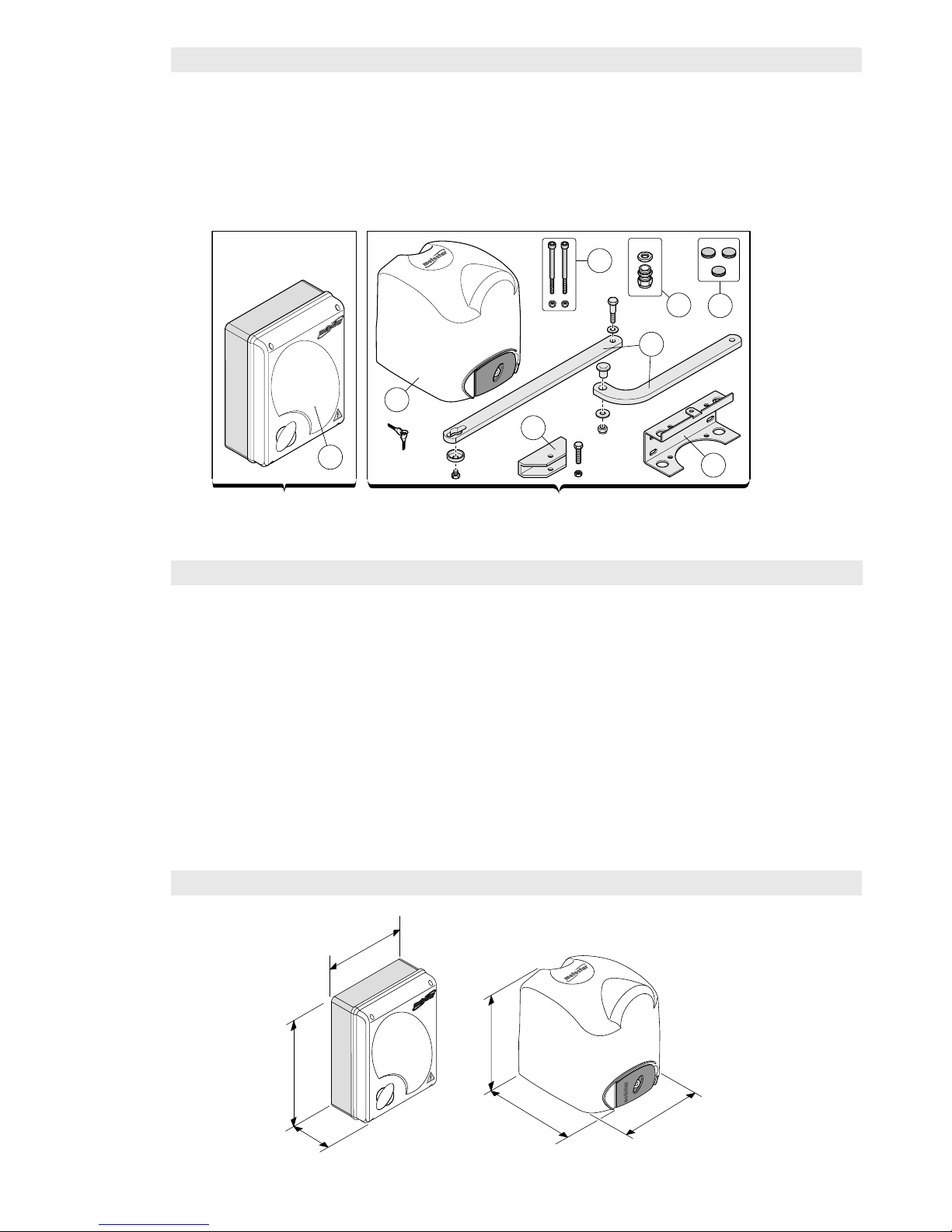
1.1 Components pag. 3
1.2 Technical features pag. 3
1.3 Dimensions pag. 3
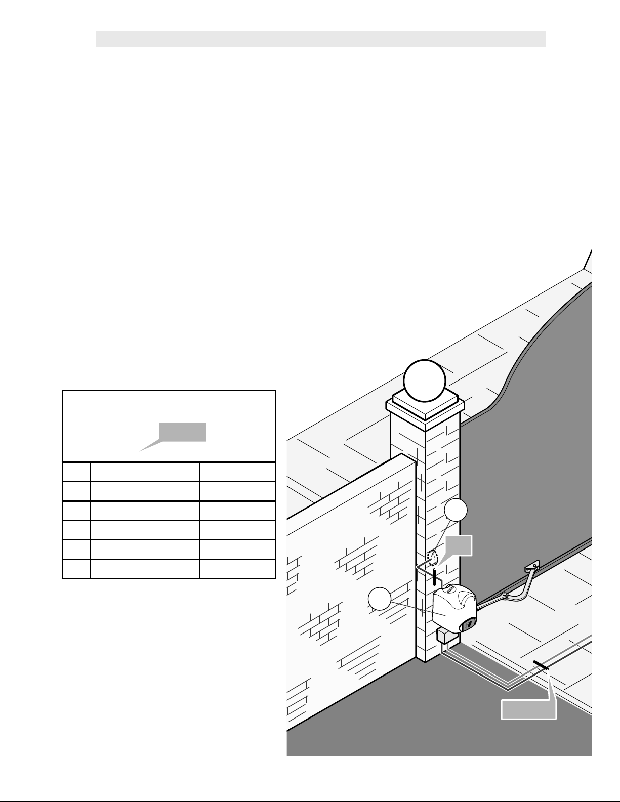
1.4 Main component parts of a standard installation pag. 4
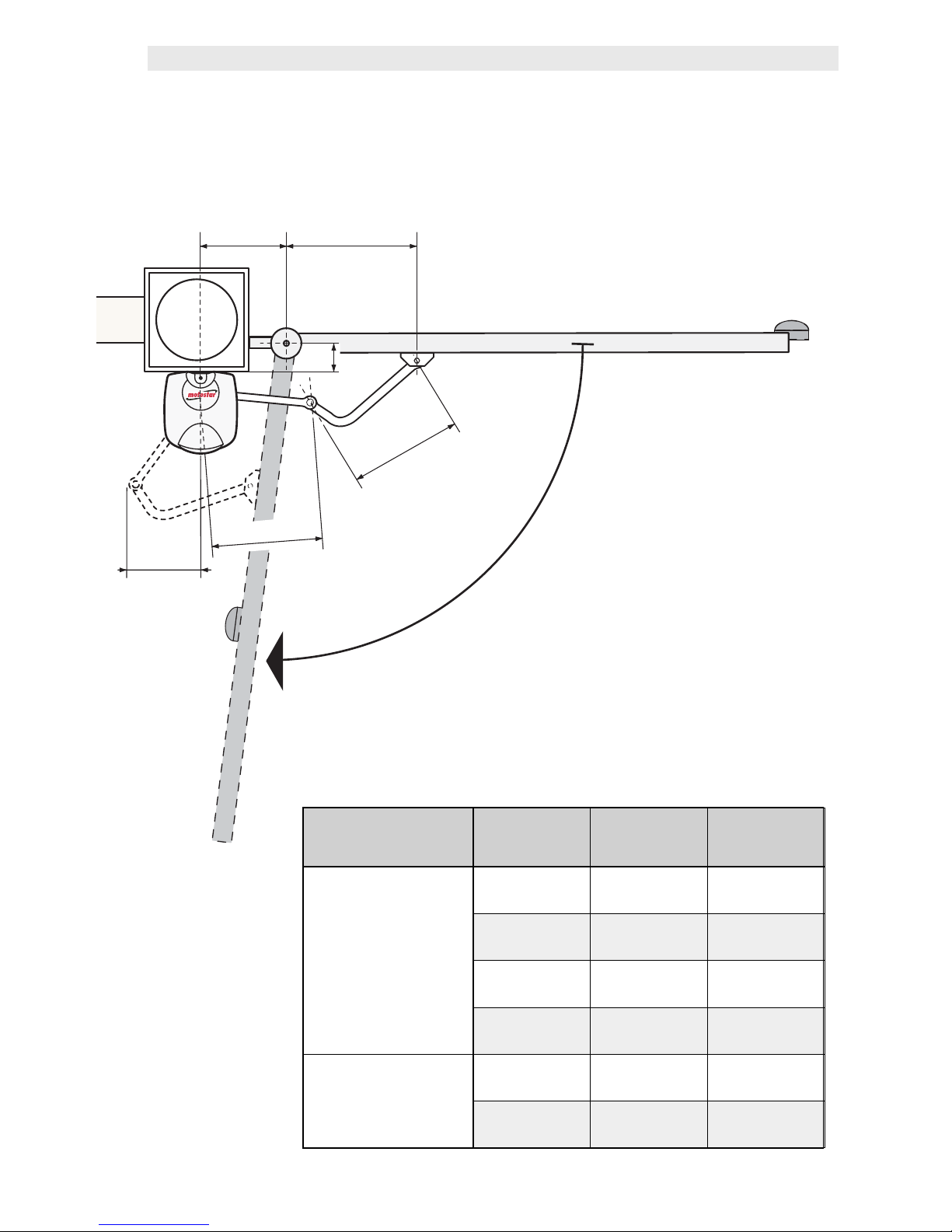
1.5 Limits to use pag. 6
2.0 Installing the gearmotor pag. 7
3.0 Control panel pag. 18
3.1 Assembling and fixing the casing pag. 20
3.2 Control board and its functions – description pag. 22
3.3 Electrical connections pag. 23
3.4 Selecting functions pag. 27
3.5 Adjusting functions pag. 29
3.6 Checking endstops adjustments pag. 30
3.7 Programming the radio code pag. 31
3.8 Control LEDs’ functions pag. 32
3.9 Final operations pag. 32
4.0 Warnings and precautions pag. 33
5.0 Troubleshooting pag. 33
6.0 Maintenance pag. 34
7.0 Dismissal and disposal pag. 36
1.0 GENERAL CHARACTERISTICS
Operator for swing gates up to 2.20 m per gate leaf, 230V A.C. powered, IP54 protection
rating, fitted with:
- autoapprendimento del codice tra trasmettitore e ricevitore radio;
- self-learning of the code between transmitter and radio receiver;
- adjustable amperometric detector for movement inversion of the opening and closing gate
leaves;
- colour-coded terminals to identify the various accessories and simplify connections;
- power up warning LEDs, programming and safety test;
- endstops for managing gate leaf stops when opening and slow-downs when closing;
- emergency release with customised key;
- power cable L = 2.5 m.

x 1 x 2
5
8
6
4
2
13
7
Pag.
3
- Manual code:
119R7179GB
119 R7179G B ver.
3.0
3.0 07/2009 - The data and information in this manual are subject to change at any time.
1.1 COMPONENT PARTS
1) Control panel
2) Gearmotor
3) Base bracket
4) Head brackets
5) Fixing nuts and screws
6) Transmission arms
7) Cable feedthroughs
8) Cable gland
1.2 TECHNICAL CHARACTERISTICS
24V D.C. self-locking gearmotor, powered by a 230V A.C. control panel.
1.3 DIMENSIONS
Power supply to control panel:
230V A.C. – 50/60Hz
Power supply to gearmotor:
24V D.C.
Max power: 140W
Nominal supply voltage: 5A max
Max thrust: 180N
Max frequency of use: 45 cycles/h
Duty cycle: 50%
Reduction ratio: 1/36
Operating temperature: from -20° to +
55°C
Overall weight including packaging: 30 Kg

4
6
Ⓑ
Ⓑ
Ⓑ+Ⓔ
Ⓑ+Ⓔ
Pag.
4
-
119R7179GB
119 R7179G B ver.
3.0
3.0 07/2009 - The data and information in this manual are subject to change at any time and without need of prior notice.
1.4 MAIN COMPONENT PARTS OF A STANDARD INSTALLATION
1) Flashing light with built-in antenna
2) Keypad selector
3) Control panel
4) Photocell
5) Junction box for passage of electrical cables
6) Gearmotors
7) Transmitters
The standard installation shown is only an example.
Check the illustrations and the contents list in the kit box you
have purchased.
Number of wires per cable section
Ⓐ
Ⓐ
+
+
Ⓑ
Ⓑ
ⒶPower supply 3 x 1,5
ⒷRX photocell 4 x 0,5
ⒸTX photocell 2 x 0,5
Ⓓflashing light 2 x 1,5
Ⓔgearmotor 3 x 1,5
Ⓕantenna RG58 cable

12
34
5
E
3
5
1
2
4
6
7
Ⓐ
Ⓐ
Ⓒ+Ⓔ
Ⓒ+Ⓔ
Ⓒ
Ⓒ
Ⓓ+Ⓕ
Ⓓ+Ⓕ
Ⓐ+Ⓑ+Ⓒ
Ⓐ+Ⓑ+Ⓒ
+Ⓓ+Ⓔ+Ⓕ
+Ⓓ+Ⓔ+Ⓕ
The data and information in this manual are subject to change at any time and without need of prior notice -
119R7179GB
119 R7179G B ver.
3.0
3.0 07/2009 - Pag.
5

240
max
AC
330
330
B
(mm)
Pag.
6
- Manual code:
119R7179GB
119 R7179G B ver.
3.0
3.0 07/2009 - The data and information in this manual are subject to change at any time.
1.5 LIMITS TO USE
Opening angle A B C
90°
140÷205 0÷50 430
140÷195 75÷100 430
140÷185 125÷150 400
140÷175 175÷200 400
110°
180÷210 0 430
200÷205 50 430
The maximum width of the gate leaf must not exceed 2.2 metres and its max weight
cannot exceed 300 kg.

Pag.
7
- Manual code:
119R7179GB
119 R7179G B ver.
3.0
3.0 07/2009 - The data and information in this manual are subject to change at any time.
2.0 INSTALLING THE AUTOMATION
GATE CHECKS BEFORE INSTALLING
• Check that the gate structure is sturdy and that
the hinges are in proper condition.
• Make sure that there is a closing and opening
mechanical door endstop (that is well secured to the
ground) to prevent over-run of the gate leaf.

68
100
min.
81.5
40
173
120
120
(mm)
Pag.
8
- Manual code:
119R7179GB
119 R7179G B ver.
3.0
3.0 07/2009 - The data and information in this manual are subject to change at any time.
1 - Set up the tubes for the
electrical connection and
junction boxes.
3 - Decide where to fix the head bracket.
Position the base plate on the post,
making sure the fixing and
application measurements
are right (see this drawing)
(see page 6).
2 - Insert the electrical
cables that come
from the junction pit into
the tubes, making sure
the sections are right
depending on the use to
be made (see installation
on page 4).
PRELIMINARY OPERATIONS AND BRACKET MOUNTING
Head bracket
Base plate

22.5
60
100
C
Pag.
9
- Manual code:
119R7179GB
119 R7179G B ver.
3.0
3.0 07/2009 - The data and information in this manual are subject to change at any time.
6 - Position the head bracket onto
the gate leaf at a “C” distance from
the axis of the hinge while taking into
account the A and B measurements as
shown in the table on page 6.
7 - Secure the bracket using securing
elements chosen according to the
gate type and materials.
4 - Secure the base plate, using securing
elements chosen according to the post
type and materials.
PRELIMINARY OPERATIONS AND BRACKET MOUNTING
5 - Insert the cable feedthroughs and the
cable gland into the base plate holes.

1
2
Pag.
10
10 - Manual code:
119R7179GB
119 R7179G B ver.
3.0
3.0 07/2009 - The data and information in this manual are subject to change at any time.
SECURING THE GEARMOTOR
1 - Remove the cover, insert
the gearmotor into the base
bracket so that it corresponds to
the 4 holes and secure it using the
supplied screws and nuts.
Warning: a sticker tag on the microswitch
shows whether that gearmotor should be
mounted to the right (DX) or to the left
(SX).
2 - Insert and secure the
straight arm into the
gearmotor shaft using plug,
screw and relative bushing.
Lubricate the bushing, insert
it into the straight arm and join
it to the curved arm using the
supplied screw, the washers
and nut.
3 -Release the
gearmotor by opening
the hatch (using the
apposite key); to lock it,
close the hatch.

Pag.
11
11 - Manual code:
119R7179GB
119 R7179G B ver.
3.0
3.0 07/2009 - The data and information in this manual are subject to change at any time.
4 - Secure the curved arm to the
head bracket using the supplied
screw and nut. Lubricate it and check
that the arm rotates freely.
5 - Perforate the cable feedthrough
to the base bracket on the side of
the cable gland.
6 - Insert the cable into the
cable gland and block it.
Connect the gearmotor cables
to the power cables coming
from the control panel (see
diagram on page 22).
SECURING THE GEARMOTOR

Pag.
12
12 - Manual code:
119R7179GB
119 R7179G B ver.
3.0
3.0 07/2009 - The data and information in this manual are subject to change at any time.
1 - With the motor released, place
the gate leaf at a distance of 5 cm
from the opening endstop.
ADJUSTING THE ENDSTOPS
LEFT HAND GEARMOTOR
- INNER VIEW -
... until the microswitch is activated.
2 - Rotate the lower cam clockwise ....
ADJUSTING THE
OPENING ENDSTOP
3 - Secure the cam using the central
screw.
Opening
microswitch
Lower
cam
Closing
microswitch
Upper
cam
Upper cam
securing screw
Lower cam
securing screw

L = 1.20 m < 2.20 m
Pag.
13
13 - Manual code:
119R7179GB
119 R7179G B ver.
3.0
3.0 07/2009 - The data and information in this manual are subject to change at any time.
ADJUSTING THE
CLOSING ENDSTOPS
1 - Release the gearmotor and
completely close the gate leaf.
2 - Rotate the upper cam counter-
clockwise ....
3 - Secure the cam using the lateral
screws.
N.B. Always adjust the opening endstop
before adjusting the closing one.
... until the switch of the micro is released.
Warning: the upper cam of the operator’s
endstop assembly is set up for gate leaf
widths ranging from 1.20 m to 2.20 m.
ADJUSTING THE ENDSTOPS

L = < 1.20 m
Pag.
14
14 - Manual code:
119R7179GB
119 R7179G B ver.
3.0
3.0 07/2009 - The data and information in this manual are subject to change at any time.
continue > adjusting the left hand closing endstop
5 - Secure the cam using the lateral
screws.
2 - Turn the cam upside down.
3 - Release the gearmotor and
completely close the gate leaf.
4 - Turn the upper cam counter-
clockwise ....
... until the switch of the micro is
released.
N.B. If the gate leaf measures less than
1.20 metres ...
1.20 metres ...
... turn the upper cam upside down and
then adjust the endstop.
1 - Remove the securing screws from
the upper cam.
ADJUSTING THE ENDSTOPS

Pag.
15
15 - Manual code:
119R7179GB
119 R7179G B ver.
3.0
3.0 07/2009 - The data and information in this manual are subject to change at any time.
RIGHT HAND GEARMOTOR
- INNER VIEW -
Opening
microswitch
Lower
cam
Closing
microswitch
Upper
cam
Upper cam
securing screw
Lower cam
securing screw
1 - With the motor released, place
the gate leaf at a distance of 5 cm
from the opening endstop.
... until the switch of the micro is
activated.
2 - Rotate the lower cam counter-
clockwise ....
ADJUSTING THE ENDSTOPS
3 - Secure the cam using the central
screw.
ADJUSTING
THE OPENING ENDSTOP

L = 1.20 m < 2.20 m
Pag.
16
16 - Manual code:
119R7179GB
119 R7179G B ver.
3.0
3.0 07/2009 - The data and information in this manual are subject to change at any time.
... until the switch of the micro is
released.
2 - Rotate the upper cam clockwise ....
3 - Secure the cam using the lateral
screws.
1 - Release the gearmotor and
completely close the gate leaf.
N.B. Always adjust the opening endstop
before adjusting the closing one.
Warning: the upper cam of the operator’s
endstop assembly is set up for gate leaf
widths ranging from 1.20 m to 2.20 m.
ADJUSTING THE ENDSTOPS
ADJUSTING
THE CLOSING ENDSTOP

L = < 1.20 m
Pag.
17
17 - Manual code:
119R7179GB
119 R7179G B ver.
3.0
3.0 07/2009 - The data and information in this manual are subject to change at any time.
N.B. If the gate leaf measure less than
1.2 metres ...
1.2 metres ...
... turn the upper cam upside-down and
then adjust the endstop.
5 - Secure the cam using the lateral
screws.
2 - Turn the cam upside down.
3 - Release the gearmotor and
completely close the gate leaf.
4 - turn the upper cam clockwise ....
... until the switch of the micro is
released.
1 - Remove the securing screws of
the upper cam.
ADJUSTING THE ENDSTOPS
continue > adjusts the right hand closing endstop

1
23
6
7
12
8
5
10
11
13 14 16 17 18 20 21 22
19
15
9
23
4
Pag.
18
18 - Manual code:
119R7179GB
119 R7179G B ver.
3.0
3.0 07/2009 - The data and information in this manual are subject to change at any time.
3.0 CONTROL PANEL
Il The control panel is made up of a two-colour ABS casing, featuring a fully opening hatch
which can be hinged either right or left. Inside, the control board featuring a receiver radio
card and transformer.
We suggest installing it in an area protected from accidental impacts or possible
tampering.

Pag.
19
19 - Manual code:
119R7179GB
119 R7179G B ver.
3.0
3.0 07/2009 - The data and information in this manual are subject to change at any time.
1 - Transformer
2 - Card fuse
3 - Trimmer for adjusting automatic
closing time
4 - Terminals for connecting the
transformer
5 - Trimmer for adjusting the
sensitivity of the obstacles
6 - Trimmer for adjusting the closing
time of the 2nd motor
7 - Buttons for memorising the radio
code
8 - Function control LED
9 - “Dip-switch” function selector
10 - Accessories fuse
11 - Line fuse
12 - Radio Card
13 - Terminals for connecting up 230V
(A.C.) power
14 - Terminals for connecting up
gearmotors
15 - Motor fuse
16 - Terminals for powering up
accessories
17 - Terminals for connecting up
warning signal accessories
18 - Terminals for connecting up the
stop button
19 - Terminals for connecting up the
opening photocells
20 - Terminals for connecting up the
command buttons
21 - Terminals with N.O. (B1-B2)
output
22 - Terminals for antenna fitted with
RG58 cable
23 - Terminals for connecting up the
partial stop photocells
LEGEND
Protection rating against
dust and liquids:
IP54
FUSE TABLE
pos.
pos.
to protect:
to protect:
Fuses:
Fuses:
15 Motors 5A-F
11 Control board (line) 1.6A-F
10 Accessories 1A-F
2Command devices
(card) 315mA-F

15 mm~
Pag.
20
20 - Manual code:
119R7179GB
119 R7179G B ver.
3.0
3.0 07/2009 - The data and information in this manual are subject to change at any time.
1-Assemble the pressure
hinges.
2-Insert the hinges into the
base of the casing (either
right or left, as you prefer) and
secure them using the supplied
screws and washers.
They slide to rotate
3.1 ASSEMBLING AND SECURING THE CASING
Before securing the casing to the wall, you need to assemble and mount the hinges on the
side you prefer.
(N.B. you may also just wish to secure the cover using the 4 screws).
Table of contents
Other Motostar Gate Opener manuals