Portamatik BETA400 Use and care manual

v1.0
REV. 04/2019
BETA400
USER’S AND INSTALLER’S MANUAL

2
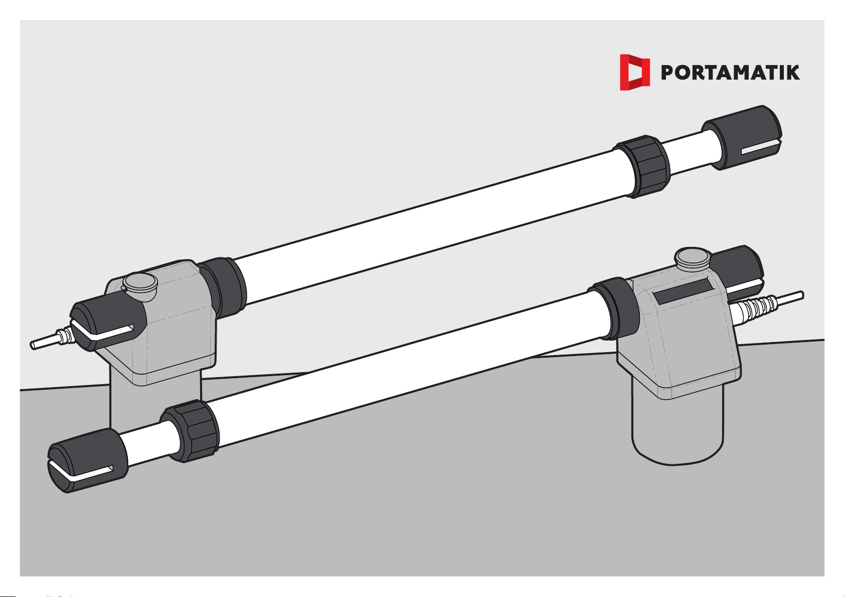
The BETA400 automation is a product exclusively
developed for the automatic opening of swing
doors.
In order to ensure correct installation and opera-
tion it is important that the INSTALLATION order
is adhered to.
SAFETY INSTRUCTIONS
CONTENT
PRÉ-INSTALLATION...............................................................................
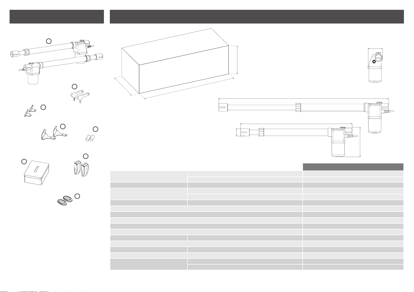
PACKAGE................................................................................................
OPERATOR..............................................................................................
INSTALLATION........................................................................................
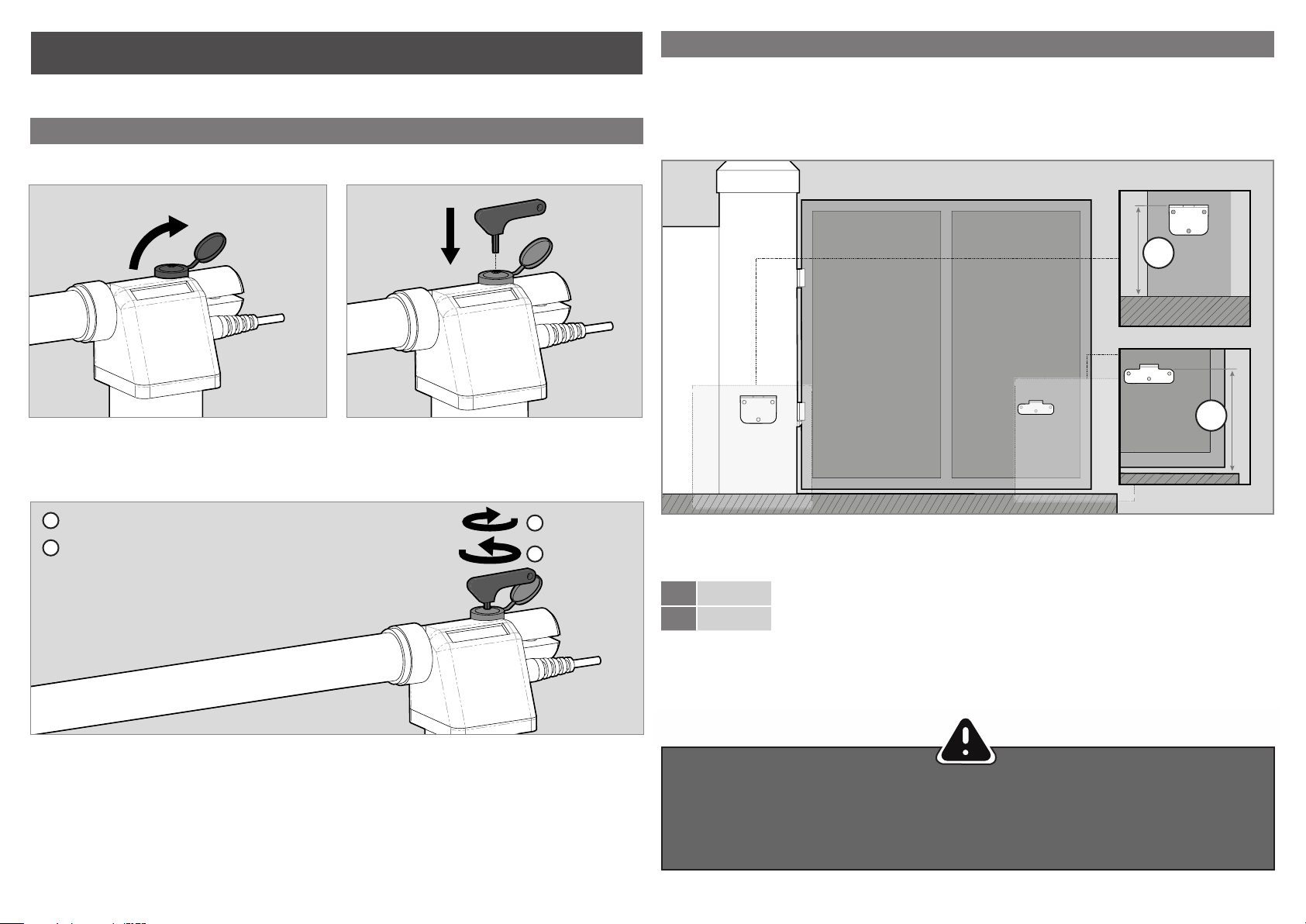
UNLOCK OPERATOR..........................................................................
HEIGHT OF THE SUPPORTS.............................................................
INTERNAL OPENING INSTALLATION QUOTAS.................................
EXTERNAL OPENING INSTALLATION QUOTAS...............................
INSTALLATION STEPS........................................................................
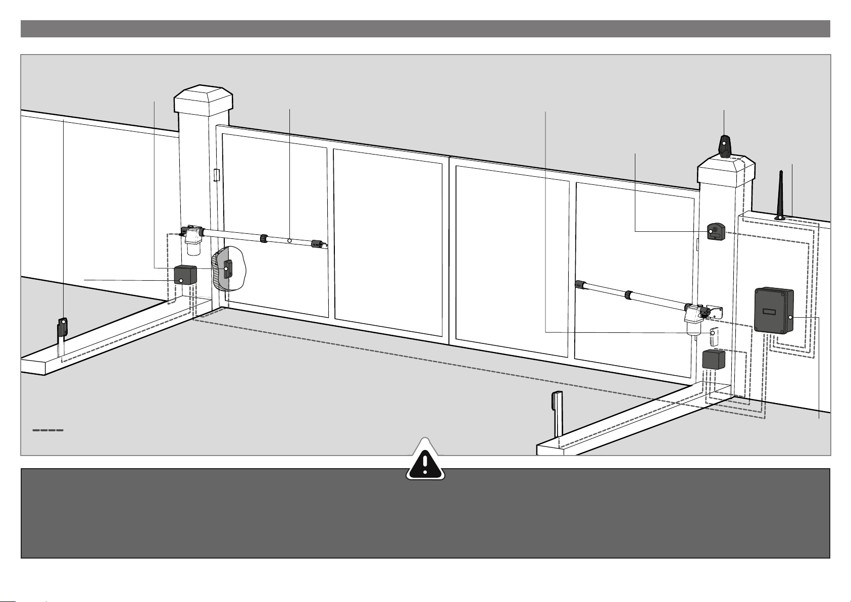
INSTALLATION MAP.............................................................................
COMPONENTS TEST..............................................................................
MAINTENANCE.......................................................................................
CLEAN STAINLESS STEEL ARM........................................................
LUBRICATE PINS................................................................................
CHECK MOTOR SUPPORTS..............................................................
TROUBLESHOOTING.............................................................................
CENTRAL CONNECTIONS..................................................................
2
2
3
3
3
4
5
5
6
7
8
8
8
8
8
9
10
PRÉ-INSTALLATION
• It is important for your safety that these instructions
are followed.
• Keep these instructions in a safe place for future re-
ference.
• The Supplier is not responsible for the improper use
of the product, or other use than that for which it was
designed.
cal wires, essentially on the power cable.
• When programming the control unit, pay particular
attention to touching only the location intended for that
purpose. Failure to do so may result in electric shock.
• The Supplier is not responsible if safety standards
were not taken into account when installing the equip-
ment, or for any deformation that may occur.
• The Supplier is not responsible for insecurity and mal-
function of the product when used with components
that were not sold by the them.
• This product was designed and manufactured strictly
for the use indicated in this manual.
• Any other use not expressly indicated may damage
the product and/or can cause physical and property
damages, and will void the warranty.
• Do not make any changes to the automation compo-
nents and/or their accessories.
• Keep remote controls away from children, to prevent
the automated system from being activated involunta-
rily.
• The customer shall not, under any circumstances, at-
tempt to repair or tune the operator. Must call qualified
technician only.
• The installer must have certified professional knowle-
dge at the level of mechanical assemblies in doors and
gates and control board programmation. He should
also be able to perform electrical connections in com-
pliance with all applicable regulations.
• The installer should inform the customer how to han-
dle the product in an emergency and provide him the
manual.
• This device can be used by children 8 year old or older
and persons whose physical, sensory or mental capa-
cities are reduced, or by persons without experience
or knowledge if they have received supervision or ins-
tructions on the use of the device in a safe manner and
understood the hazards involved. Children should not
play with the device. Cleaning and maintenance by the
user must not be carried out by unsupervised children.
• Before installing, the installer must verify that the tem-
perature range indicated on the operator is appropriate
to the location of the installation.
• Before installing, the installer must verify that the
equipment to be automated is in good mechanical
condition, correctly balanced and opens and closes
properly.
• If the operator is to be installed at a level higher than
2,5 m above ground level or other level of access, ,
should be followed the minimum safety and health re-
quirements for the use of work equipment workers at
work in Directive 2009/104/EC of the European Parlia-
ment and of the Council of 16th September of 2009.
• In the case of the equipment where the automation
will be installed, have a pedestrian door, be aware that
it must be closed when the operator is activated.
• After installation, make sure that the mechanism is
properly adjusted and that the protection system and
any manual unlocker works correctly.
• In order to protect the electrical cables against me-
chanical stress, you should use conduit for the electri-
This product is certified in accordance with
European Community (EC) safety stan-
dards.
This product complies with Directive
2011/65/EU of the European Parliament
and of the Council, of 8 June 2011, on the
restriction of the use of certain hazardous
substances in electrical and electronic
equipment.
(Applicable in countries with recycling
systems). This marking on the product or
literature indicates that the product and
electronic accessories (eg. charger, USB
cable, electronic material, controls, etc.)
should not be disposed of as other hou-
sehold waste at the end of its useful life.
To avoid possible harm to the environ-
ment or human health resulting from the
uncontrolled disposal of waste, separate
these items from other types of waste and
recycle them responsibly to promote the
sustainable reuse of material resources.
Home users should contact the dealer
where they pruchased this product or the
National Environment Agency for details
on where and how they can take these
items for environmentally safe recycling.
Business users should contact their ven-
dor and check the terms and conditions of
the purchase agreement.
This product and its electronic accessories
should not be mixed with other commercial
waste.
This marking indicates that the procut
and electronic accessories (eg. charger,
USB cable, electronic material, controls,
etc.) are susceptible to electric shock by
direct or indirect contact with electricity.
Be cautious when handling the product
and observe all safety procedures in this
manual.

3
99
194
130
766
11 6 9
300
855
1
2
3
45
6
7
8
OPERATOR
1 • Motor BETA400 (2x)
2 • Release keys (2x)
3 • Front brackets (2x)
4 • Rear brackets (2x)
5 • Capacitors (2x)
6 • Photocells (2x)
7 • Remote Controls (2x)
8 • Contral board MC2 (1x)
9 • User’s manual(1x)
The dimensions of the BETA400 operator are in milimeters (mm) throughout the manual.
PACKAGE
BETA400
• Power Supply 230V 230Vac 50/60Hz
110V AC 110V 50/60Hz
• Power 230/110V 280W
• Current 230V 1,3A
110V 2,5A
• RPM 230/110V 1400 RPM
• Noise Level LpA <= 50 dB (A)
• Force 2300N
• Operating temperatures -25°C ~75°C
• Thermal protection 150°C
• IP IP54
• Working frequence 230/110V 25%
• Opening time 13 seg. a 18 seg.
• Course 400mm
• Max leaf lenght 3000mm
• Capacitor 230V 10µF
110V 25µF
The specifications of the operator are as follows:

4
A
B
A? mm
BA-10mm
B
B
D
D
3 • Turn the key 180 ° in the direction shown in the
figure to unlock.
4 • Automatism unlocked.
Note • For automatic operation, it must be locked again
by turning the key in the opposite direction.
The operator should be installed with a small declination on the front, to prevent water infiltration by the extension
arm.
To this end, the front support plate must be attached to the gate with a height lower than the height of the rear
support plate. See the example below:
Quota A •Vertical distance from the floor to the top of the rear support plate.
Quota B • Vertical distance from the floor to the top of the front support plate.
Example:
• If the height of the back support plate (Quota A) is set to 600mm, then the height of the front support plate
(Quota B) will be 590mm (600mm-10mm).
1 • Define Quota A (this can be any dimension of your choice).
2 • After defining Quota A, subtract 10mm and the result is Quota B.
HEIGHT OF THE SUPPORTS
It is very important that these quotas be respected!
Only in this way can the correct operation and durability of the automatic controls be ensured!
It is also very important that the floor is level!
To lock turn the key counterclockwise.
To unlock turn the key clockwise.
UNLOCK OPERATOR
INSTALLATION
1 • Open the plastic cover in the back. 2 • Insert the key into the unlocking shaft entrance.

5
W1095 a 1100 W695 a 700
X
W
Y
X
Y
W
• When installing the automation, it is mandatory to respect the quotas x and y, as indicated in the tables.
Within this area, it is possible to identify the maximum opening angle that the gate reaches in these quotas.
INTERNAL OPENING INSTALLATION QUOTAS EXTERNAL OPENING INSTALLATION QUOTAS
In the diagrams illustrated above, the quotas for the installation of the automatisms are defined.
X, Y and W shown in (mm)
• It is very important that these quotas be respected! Only in this way can the correct operation and
durability of the automatic controls be ensured!
Subtitle:
Quota X - Horizontal distance between the axis of the door hinge and the rear axle of engine rotation.
Quota Y - Vertical distance between the axis of the door hinge and the rear axle of engine rotation.
Quota W - Distance between the axes of the engine supports.
(EXTERNAL)
(INTERNAL)
Axis of rotation of the
motor, on the rear support.
Opening
direction
Axis of rotation of the gate
(center of the door hinge)
Axis of rotation of the
motor, on the front bracket
Closing mechanical
stopper
Opening mechanical stopper.
(EXTERNAL)
(INTERNAL)
Axis of rotation of the gate
(center of the door hinge)
Axis of rotation of the motor,
on the front support
Closing mechanical stopper
Axis of rotation of the
motor, on the rear support
Opening
direction
Opening
mechanical stopper
BETA400 | MAX. OPENING ANGLE | INTERNAL
Quotas Y Quotas X
140 150 160 170 180 190 200 210 220 230
130 ----------
140 ----------
150 98º 102º 105º 109º 112º 109º 105º 102º 99º 97º
160 98º 101º 105º 108º 110º 105º 102º 99º 96º 94º
170 98º 101º 104º 107º 105º 101º 98º 96º 94º 92º
180 98º 101º 104º 106º 101º 98º 95º 93º 91º -
190 97º 101º 104º 101º 98º 95º 92º 91º - -
200 97º 100º 101º 97º 94º 92º - - - -
210 97º 100º 97º 93º 91º -----
220 97º 96º 93º 90º ------
230 95º 92º --------
BETA400 | MAX. OPENING ANGLE | EXTERNAL
Quotas Y Quotas X
140 150 160 170 180 190 200 210 220 230
130 93º 96º 99º 102º 105º 107º 110º 106º 101º 97º
140 92º 95º 98º 101º 104º 106º 108º 103º 98º 94º
150 92º 95º 98º 100º 103º 105º 105º 100º 95º 92º
160 91º 94º 97º 100º 102º 104º 101º 97º 93º -
170 91º 94º 96º 99º 101º 104º 98º 94º 90º -
180 91º 93º 96º 98º 101º 100º 95º 91º - -
190 90º 93º 95º 98º 100º 97º 92º ---
200 90º 93º 95º 97º 99º 94º - - - -
210 90º 92º 95º 97º 96º 91º - - - -
220 -92º 94º 96º 93º -----
230 -92º 94º 95º ------

6
INSTALLATION STEPS
Observe the installation dimensions mentioned on the previous pages.
It is important that this installation order is adhered to!
Otherwise, it is not possible to ensure a correct installation and the automatic controls may not work correctly!
2 • Fasten rear bracket
• The Rear Support must be fixed to the pillar or wall,
respecting the dimensions given on the previous pages.
This can be fixed using screws with mechanical or
chemical bushing, welding process, or other of your
choice as long as it provides an appropriate fixation of
the Support.
5 • Test motion
• Put the bolts in each holder with a small amount of
lubricant so that there is no friction. Move the gate by
hand to check that the gate opens and closes without
hindrance.This will ensure that the automation is not
subject to problems during its operation.
3 • Open the engine covers and remove the engine
bolts.
•
Before installing the motor, open the covers and
remove the dowels from the brackets. At the end of the
installation, you should close the plastic covers for a
better visual finish of the operator.
1 • Fasten front bracket
• The Front Bracket should be fixed to the gate,
respecting the height and distance dimensions for the
Rear Bracket.
This can be fixed using screws, welding process, or
other of your choice as long as it provides proper
attachment of the Holder.
6 • Connect the operator to the control panel and
configure the control devices.
•
With the automation already installed, connect it to the
control unit for configuration (see the control panel manual
to be configured).
You must also configure the desired control devices (con-
trols, buttons, etc.) and other additional components such
as antenna, firefly, key selector, among others.
4 • Place automation on the brackets.
• You should grease the pins before loading them.

7
INSTALLATION MAP
• It is important to use a stop at the opening and closing of the gate.
• If this is not observed, the automation components may be subject to unprepared effort and may be dama-
ged.
• It is important to use junction boxes for connections between motors, components and switchgear. All cables
must enter and exit under the junction box and control unit box.
• INTERIOR
PHOTOCELLS
• JUNCTION
BOX
• EXTERIOR
PHOTOCELLS • EXTERIOR
PHOTOCELLS
• KEY
SELECTOR
• MOTOR BETA400 • WARNING
LAMP
• ANTENNA
• CONTROL
BOARD
LEGEND:
• Connection cables

8
• With a cloth soaked in lubricating spray, clean all
debris that accumulates in the stainless steel tube of
the automation.
• Apply a small dose of lubricating spray through the
tube and wipe dry with a dry cloth to remove excess
lubricant leaving a homogenous layer through the tube.
MAINTENANCE
All tests must be carried out by specialized technicians due to the serious danger related to the misu-
se of electrical systems!
These maintenance measures must be
carried out within 1 year to maintain the
correct functioning of the operator.
1 • Connect the power wires to the terminal, as shown.
2 • Connect the automation wires to the terminal, inserting a capacitor into the opening and closing wires.
3 • After these connections are completed, plug into a 230V / 110V outlet, depending on the motor / power unit
being tested.
CHECK MOTOR SUPPORTS
LUBRICATE PINS
CLEAN STAINLESS STEEL ARM
• Open the front and rear brackets.
• Place a small amount of lubricant in the holes that con-
tain the support bolts.
• Put the covers back on their respective holders.
• Make sure that the supports remain securely atta-
ched to the pillars and gate for proper operation of the
equipment
COMPONENTS TEST
To detect if the fault is in the control panel or the motor, it is sometimes necessary to carry out tests with a direct
connection to a 230V / 110V power supply.
For this purpose, it is necessary to insert a capacitor into the connection so that the automation can operate (check the
type of condenser to be used in the product manual).
The diagram below shows how this connection should be made and how to interleave the different wires of the
• To perform the tests you do not need to remove the automation from the place where it is installed, becau-
se in this way you can see if the automatism connected directly to the chain can function correctly.
• You must use a new capacitor during this test to ensure that the problem is not in the condenser.
OPERATOR
Capacitor
8μF
1
2
3
2
COM 1
COM 2
COM
Ground
Wire
Phase 2
Phase 1
Abre
Fecha
Motor
Power Supply 2
Power Supply 1

9
TROUBLESHOOTING
Anomaly Procedure Behavior Procedure II Discovering the origin of the problem
• Motor
doesn't work
• Make sure you
have 230V power
supply connected to
control board and if it
is working properly.
• Still not working • Consult a qualified
technician.
• Motor
doesn’t move
but makes
noise
• Unlock motor and
move the gate by
hand to check for
mechanical problems
on the movement.
• Encountered
problems?
• Consult a qualified gates
technician.
• The gate moves
easily?
• Consult a qualified
technician.
• Gate doesn’t
make
complete
route
• Unlock motor and
move the gate by hand
to closed position.
Lock motor again
and turn of power
supply for 5 seconds.
Reconnect it and send
order to open gate
using transmitter.
• Gate opened but
didn’t close again.
1 • Check if there is any
obstacle in front of the
photocells;
2 • Check if any of the control
devices (key selector, push
button, video intercom, etc.)
of the gate
are jammed and sending
permanent signal to control
unit;
3 • Consult a qualified
technician.
• Gate doesn’t
make
complete
route
• Unlock motor and
move gate by hand to
check for mechanical
problems on the gate.
• Encountered
problems?
• Consult a qualified gates
technician.
• The gate moves
easily?
• Consult a qualified
technician.
1 • Open control board and check if
it has 230V power supply;
2 • Check input fuses of the
control board;
3 • Disconnect the motor from
control board and test them by
connecting directly to power
supply in order to find out if they
have problems (see page 7).
4 • If the motor works, problem is
on the control board.
Pull it out and send it to our
technical services for diagnosis;
5 • If the motor doesn’t work,
remove them from installation site
and send to our technical services
for diagnosis.
1 • Check capacitor, testing
operator with a new one;
2 • If capacitors are not the
problem, disconnect motor from
control board and it them by
connecting directly to power
supply in order to find out if it has
problems (see page 7);
3 • If the motor works, the
problem is from control board.
Pull it out and send it to our
technical services for diagnosis;
4 • If the motor doesn’t work,
remove them from installation site
and send to our technical services
for diagnosis.
1 • Check capacitors, testing with
new capacitors.
2 • If capacitors are not the
problem, disconnect motor
from control board and test it
by connecting directly to power
supply in order to find out if it is
broken;
3 • f the motor doesn’t work,
remove it from installation site
and send to our technical services
for diagnosis.
4 • If motor work well and move
gate at full force during the
entire course, the problem is
from controller. Set force using
trimmer on the board. Make a new
working time programming, giving
sufficient time for opening and
closing with appropriate force .
5 • If this doesn’t work, remove
control unit and send it to
technical services.
NOTA: Setting force of the
controller should be sufficient
to make the gate open and close
without stopping, but should stop
and invert with a little effort from
a person.
In case of safety systems failure,
the gate shall never cause
physical damaged to obstacles
(vehicles, people, etc).
All control boards have LEDs that easily allow
to conclude which devices are with anomalies.
All safety devices LEDs (DS) in normal
situations remain On.
All "START" circuits LEDs in normal situations
remain Off
If LEDs devices are not all On, there is some
security systems malfunction (photocells,
safety edges), etc.
If "START" circuits LEDs are turn On, there is a
control device sending permanent signal
A) SECURITY SYSTEMS:
1 • Close with a shunt all safety systems on
the control board (check manual of the control
board in question).
If the automated system starts working
normally check for the problematic device.
2 • Remove one shunt at a time until you find
the malfunction device.
3 • Replace it for a functional device and check
if the motor works correctly with all the other
devices. If you find another one defective,
follow the same steps until you find all the
problems.
B) START SYSTEMS:
1 • Disconnect all wires from START terminal
input.
2 • If the LED turned Off, try reconnecting one
device at a time until you find the defective
device.
NOTE:
In case procedures described in sections A)
and B) don’t result, remove control board and
send to our technical services for diagnosis;
1 • Check all motion axis and associated motion systems related with the gate to find out what is the problem.

10
L N
LAMP MOTORE 1
AP COM CH
MOTORE 2
AP COM CH VPUL
SERR. PED
PUL PED DS1 DS2
INB.CMD.AP
CODE
T.MOTOR
T. PAUSA
CODE PED
T.MOT.PED
T.RIT.ANT
PL
1 1 12 2 23 3 34 45 56 67 78 89 9 1110 10 12
L N
DS1 DS2
110V
110V
COM NC
CONTACT
~ ~
POWER
12V/24V
~ ~
POWER
12V/24V
~ ~
COM NC
CONTACT
POWER
12V/24V
~ ~
POWER
12V/24V
CENTRAL CONNECTIONS
Fotocélulas
Exteriores*
Fotocélulas
Interiores*
• Motor 1 abre primeiro que Motor 2
• Motor 2 fecha primeiro que Motor 1
• Deve ser intercalado um
condensador de 8µ em cada motor,
nos fios de abertura e fecho, como
exemplificado acima.
NOTA • Se algum motor andar em
sentido contrário, troque os fios
castanho e preto desse motor um pelo
outro para alterar o funcionamento.
Abertura
Completa
(2 folhas)
Fechadura
Pirilampo
Antena
Fio Terra
Preto
Preto
Fio Terra
Azul
Azul
Castanho
Castanho
Abertura
Pedonal
(1 folha)
Motor 1
Motor 2
Fechar os circuitos
com ponte (shunt)
quando não usar
o circuito de
fotocelulas!
(9
∑
8 - 9
∑
10)
* Para mais
informações
consulte o manual
das fotocélulas a
instalar.
This manual suits for next models
2
Table of contents
Other Portamatik Gate Opener manuals