Motostar ESC500 User manual

ITALY
MADE IN
ESC500
W
A
R
R
A
N
T
Y
•
G
A
R
A
N
T
I
E
•
G
A
R
A
N
Z
I
A
•
G
A
R
A
N
T
I
A
•
G
A
R
A
N
T
I
E
•
G
A
R
A
N
T
I
E
•
Y
E
A
R
S
•
A
N
S
•
A
N
N
I
•
A
Ñ
O
S
•
A
N
O
•
J
A
H
R
E
•
3
Installation
manual
SWING-GATE
SWING-GATE
OPERATOR
OPERATOR
Max. leaf
width 2.3 m
English
Français
Italiano
Español
Português
Deutsch
Türk

2
-
FG00666M07
-
1
- 03/2017
ENGLISH
Summary
GENERAL WARNINGS ................................................................3
KEY...........................................................................................5
DESCRIPTION . .......................................................................... 5
Intended use .........................................................5
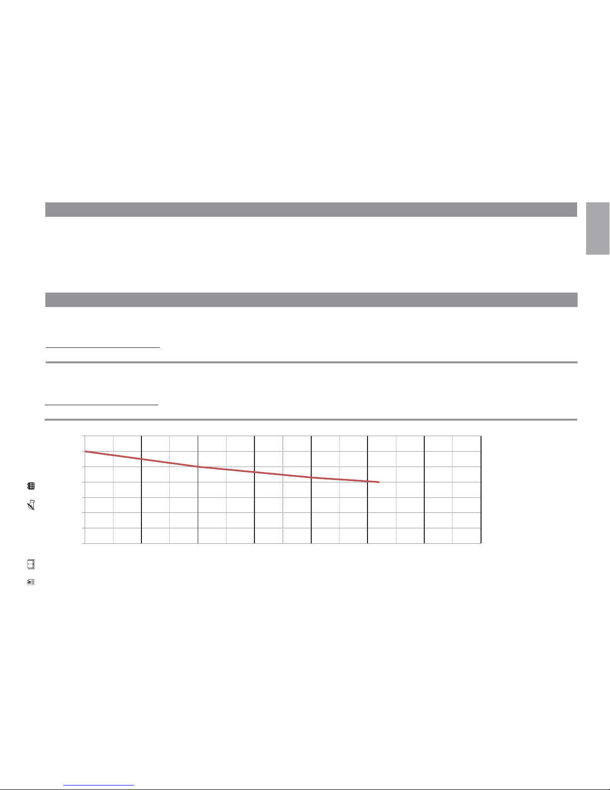
Limits to use .........................................................5
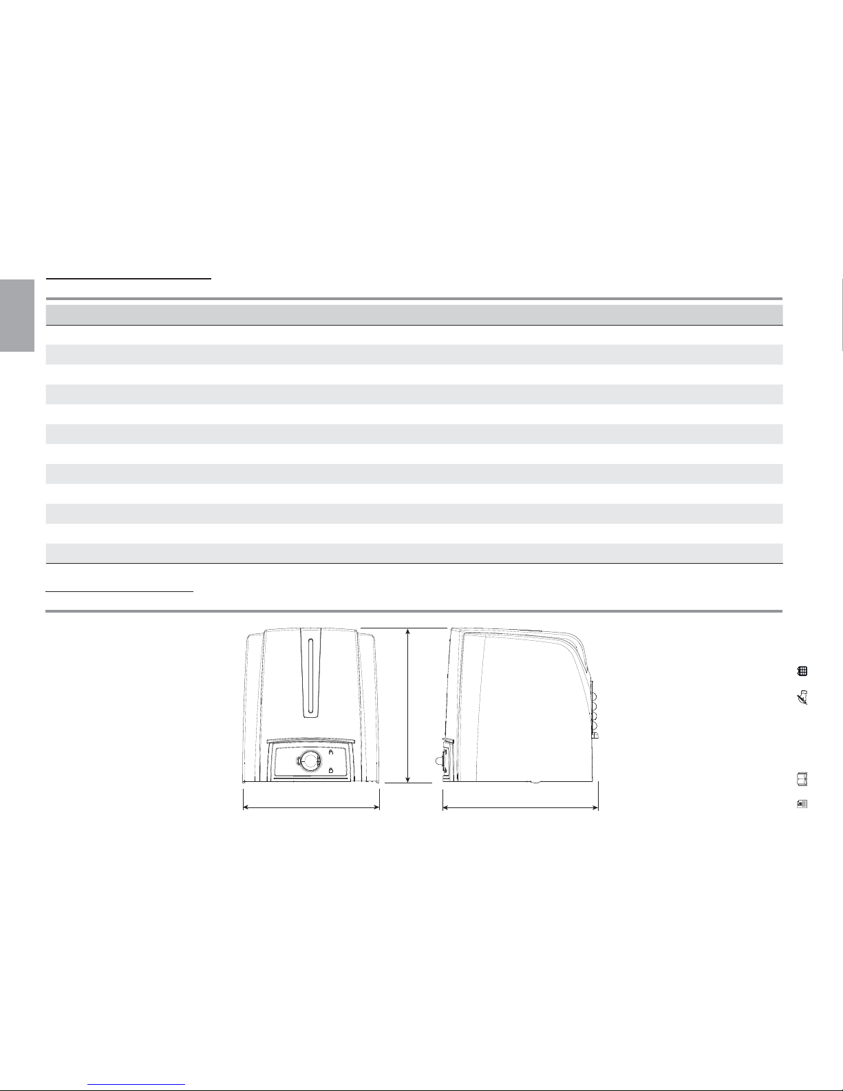
Technical data... ....................................................6
Dimensions.. .........................................................6
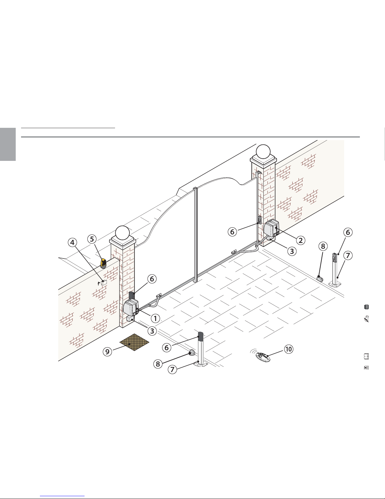
Description of parts ... ...........................................7
Standard installation .. ...........................................8
INSTALLATION .......................................................................... 9
Preliminary checks . ...............................................9
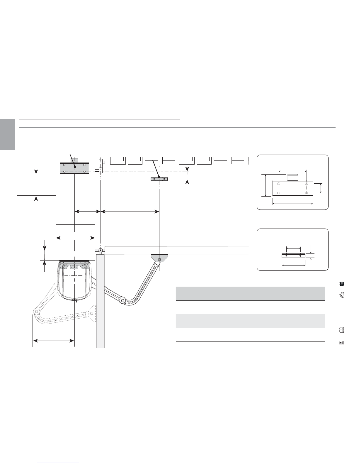
Checking the application measurements and sizes ... 10
Cable type and minimum thicknesses ... ................. 11
Preliminary operations ......................................... 12
Fastening the brackets......................................... 13
Fastening the operator.... .................................... 15
Fastening the mechanical stops............................. 18
Establishing the limit-switch points. ...................... 20
CONTROL BOARD .. .................................................................. 22
Main components .. ............................................. 22
ELECTRICAL CONNECTIONS .... ................................................. 23
Power supply.... .................................................. 23
Solenoid lock ....................................................... 23
Operator and gearmotor . .................................... 24
Command and control devices ............................... 26
Safety devices .. .................................................. 27
Signalling devices ... ............................................. 28
PROGRAMMING... .................................................................. 29
Description of programming commands ................. 29
Functions menu .................................................. 30
SETTING UP.... ........................................................................36
Motor type . ....................................................... 36
Number of motors . ............................................. 36
Motor test.. ....................................................... 37
Self-learning of the gate-leaf travel. ...................... 38
USER MANAGEMENT ...............................................................40
Entering a user with an associated command ......... 40
Deleting a single user. ......................................... 41
ILLUSTRATION OF THE SLOW-DOWN AND APPROACH AREAS AND
POINTS ...................................................................................42
ERROR MESSAGE.. ..................................................................43
FINAL OPERATIONS..................................................................43
OUTWARD OPENING CONNECTIONS AND INSTALLATIONS.. ......44
Application measurements and sizes ...................... 44
Fastening the mechanical stops............................. 45
Establishing the limit-switch points. ...................... 45
Electrical connections. ......................................... 46
DISMANTLING AND DISPOSAL .................................................48
DECLARATION OF CONFORMITY................................................48

3
-
FG00666M07
-
1
- 03/2017
ENGLISH
This product must only be used for its specifically intended
purpose. Any other use is dangerous. LABEL HABITAT SAS is
not liable for any damage caused by improper, erroneous or
unreasonable use. • The product described in this manual is
defined as a piece of “partly completed machinery” pursuant
to the Machinery Directive 2006/42/EC. The term "partly
completed machinery" means an assembly which is almost
machinery but which cannot in itself perform a specific
application. Partly completed machinery is only intended to
be incorporated into or assembled with other machinery or
other partly completed machinery or equipment, thereby
forming machinery to which Directive 2006/42/EC applies;
The final installation must comply with European Directive
2006/42/EC and the other reference European standards:
EN 13241-1, EN 12453, EN 12445 and EN 12635. Given
the above, all operations indicated in this manual
must be performed exclusively by expert, qualified
personnel. • The operator cannot be used with a gate
that includes a pedestrian entrance, unless it can only
be actioned with the pedestrian entrance in the safety
position • Make sure that you avoid trapping anything
between the gate and the fixed parts around it, when the
gate has moved • Before installing the operator, check
that the gate is in good mechanical condition and correctly
balanced, and that it closes properly. If this is not the case,
do not continue until you have complied with the safety
requirements • Make sure that there is an opening and
closing limit switch • Ensure the operator is installed on
a resistant surface, protected from possible knocks •
Make sure that appropriate mechanical stops are already
present • If the operator is installed at less than 2.5 m
from the ground or other access level, check whether any
protective devices or warning signs are needed, for safety
purposes, around dangerous points• Do not install the
WARNING: Important safety instructions.
Follow all instructions as incorrect installation may result in
serious injury.
GENERAL WARNINGS

4
-
FG00666M07
-
1
- 03/2017
ENGLISH
operator upside down or onto elements that could bend
with the weight. If necessary, add reinforcements to the
anchoring points • Do not install on leaves that are not
level • Check that any garden sprinkler systems do not wet
the operator from below • Cordon off the site carefully to
prevent any unauthorised persons, particularly children/
minors, from accessing the area • Put warning signs in
a visible place in the areas where they are required (e.g.
a panel on the gate) • Use suitable protection to avoid
mechanical danger caused by people being in the area in
which the machine operates (e.g. avoid crushing fingers
between the transmission arm and mechanical stops, avoid
being crushed when the gate opens, etc.). • The electrical
cables must pass through the cable glands and must not
come into contact with parts that may become hot during
use (motor, transformer, etc.). • All command and control
devices must be installed at least 1.85 m from the perimeter
of the area in which the gate moves, or where they cannot
be reached from the outside through the gate • All hold-to-
run switches must be positioned in places where the moving
gate leaves, transit areas and driveways are fully visible,
but nonetheless away from the moving parts • Unless the
device is key-operated, the control devices must be installed
at 1.5 m at least, and in a place that is not accessible to the
public • Before delivering the product to the user, check
that the system complies with the harmonised standard in
the Machinery Directive 2006/42/EC. Make sure that the
operator has been suitably adjusted and that the safety and
protective devices, as well as the manual release, function
correctly • Apply a permanent label that describes how to
use the manual release mechanism next to the control •
Please ensure that the end user receives all use manuals for
the products that make up the final machinery.

5
-
FG00666M07
-
1
- 03/2017
0
50
100
150
200
250
300
350
1 1,25 1,5 1,75 2 2,25 2,5 2,75
ENGLISH
KEY
This symbol shows the parts which must be read with care.
⚠This symbol shows the parts which describe safety issues.
☞This symbol indicates what should be communicated to users.
MEASUREMENTS, UNLESS OTHERWISE STATED, ARE IN MILLIMETRES. THE DATA AND INFORMATION SHOWN IN THIS MANUAL ARE TO BE CONSIDERED SUBJECT TO CHANGE
AT ANY TIME AND WITHOUT THE NEED FOR ANY ADVANCE WARNING.
DESCRIPTION
Complete system with control board, movement control and obstruction-detecting devices plus mechanical end-stops for swing
gates with leaves up to 2.3 m.
Intended use
This operator is designed to power swing gates for residential and apartment block use.
Any installation and/or use other than that specified in this manual is forbidden.
Gate-leaf weight (kg)
Gate-leaf length (m)
⚠We suggest you
always fit a solenoid
lock onto swing
gates for a more
reliable closure.
Limits to use

6
-
FG00666M07
-
1
- 03/2017
200 235
230
ENGLISH
Technical data
Model ESC500CB ESC500
Protection rating (IP) 54
Power supply (V - 50/60 Hz) 230 AC -
Motor power supply (V) 24 DC
Stand-by consumption (W) 5.5
Power (W) 140
Torque (Nm) 180 max
Opening time at 90° (s) from 13 to 30
Duty cycle (%) INTENSIVE SERVICE
Operating temperature (°C) from -20 to +50
Apparatus class I
Weight (Kg) 12 10.5
Sound pressure level (dB) (A) ≤70
Dimensions
(mm)

7
-
FG00666M07
-
1
- 03/2017
ENGLISH
Description of parts
1. Operator (ESC500CB)
2. Gearmotor (ESC500)
3. Control board
4. ☞Release hatch
5. Transmission arms
6. Jointed arm
7. Mechanical stops
8. Gate brackets
9. Post brackets
10. Rubber shims

8
-
FG00666M07
-
1
- 03/2017
ENGLISH
Standard installation
1. Operator (ESC500CB)
2. Gearmotor (ESC500)
3. Junction boxes
4. Key-switch selector
5. Flashing light
6. Photocells
7. Photocell post
8. Mechanical stop
9. Junction pit
10. Transmitter

9
-
FG00666M07
-
1
- 03/2017
ENGLISH
Preliminary checks
⚠Before installing the operator:
• make sure that the gate structure is sturdy enough, the hinges work efficiently and that there is no friction
between the fixed and moving parts;
• make sure you have fitted opening and closing mechanical gate stops;
• make sure you have set up a suitable multiple-pole cut-off device along the power
supply that is compliant with the installation rules. It should completely cut off
the power supply according to category III surcharge conditions;
• make sure that any connections inside the case (for protective
circuit continuity) are fitted with extra insulation as
compared to the other conductive parts inside;
• check that the points the motors and devices
are fixed at are in areas protected from
knocks and are sufficiently solid;
• set up suitable tubes and conduits for
the electric cables to pass through,
making sure they are protected from any
mechanical damage.
INSTALLATION
⚠Installation must be carried out by expert qualified personnel and in full compliance with the regulations in force.

10
-
FG00666M07
-
1
- 03/2017
AB
120 min
C
47,5
310 max
200 min
173
94
40
120
100
60
18
ENGLISH
Checking the application measurements and sizes
Check where you will fix the gate bracket and identify where to fix the gate-post bracket, respecting the measurements shown in the
diagram and the table.
Leaf opening arc (°) A B C
90° 140 420 0 to 200
90° 160 to 180 380 200
110° 200 to 220 400 0 to 50
POST BRACKET
GATE BRACKET

11
-
FG00666M07
-
1
- 03/2017
ENGLISH
Cable type and minimum thicknesses
Connection cable length
< 20 m 20 < 30 m
Power supply to the 230 V AC electronic board (1P+N+PE) 3G x 1.5 mm23G x 2.5 mm2
24 V DC gearmotor 3 x 1.5 mm23 x 2.5 mm2
Solenoid lock 2 x 0.5 mm2
Flashing light 2 x 0.5 mm2
Command and control devices 2 x 0.5 mm2
TX Photocells 2 x 0.5 mm2
RX photocells 4 x 0.5 mm2
When operating at 230 V and outdoors, use H05RN-F-type cables that are 60245 IEC 57 (IEC) compliant; when indoors,
use H05VV-F-type cables that are 60227 IEC 53 (IEC) compliant. For power supplies up to 48 V, you can use FROR 20-22 II-type
cables that comply with EN 50267-2-1 (CEI).
If cable lengths differ from those specified in the table, establish the cable cross-sections according to the actual power
draw of the connected devices and in compliance with regulation CEI EN 60204-1.
For multiple, sequential loads along the same line, the dimensions on the table need to be recalculated according to the actual
power draw and distances. When connecting products that are not specified in this manual, please refer to the documentation
provided with the product.

12
-
FG00666M07
-
1
- 03/2017
ENGLISH
Preliminary operations
⚠The following illustrations are examples. The space for fastening the operator and accessories varies depending on their size. The
fitter must choose the most suitable solution.
The following illustrations show a standard installation with a gearmotor and transmission arms to the left of a gate that opens
inwards. Installations with the gearmotor and transmission arms on the right are symmetrical.
Warning! For gates that open outwards, see the chapter "OUTWARD OPENING CONNECTIONS AND INSTALLATIONS"
Fit junction boxes and corrugates tubes for incoming connections from the junction pit.
The number of tubes depends on the type of system and the accessories you are going to fit. Lay at least 2 corrugated tubes
where the operator is fitted (on the leaf that opens first).

13
-
FG00666M07
-
1
- 03/2017
120
60
40
47,5
ENGLISH
Fastening the brackets
Mark the spots where the gate-post bracket and gate bracket will be fitted.
The fixing measurements are given in the section CHECKING THE APPLICATION MEASUREMENTS AND SIZES.
Drill the anchoring points, insert the dowels or use plugs that will hold the brackets.
The drawings are examples. The installer must choose the most suitable set up according to the type and thickness of the
gate leaf.

14
-
FG00666M07
-
1
- 03/2017
ENGLISH
Use suitable screws to fasten the brackets.
Fit the rubber shim into the post bracket.
⚠Lay the electric cables needed for the connections and run them through the cable glands; fasten them using the clamp on the
post bracket.

15
-
FG00666M07
-
1
- 03/2017
UNI 5931 8x80
UNI 7070 M8
ENGLISH
Fastening the operator
Fit the gearmotor into the gate-post bracket and tighten the nuts and bolts.
Fit the plug into the hole on the gearmotor drive-shaft.

16
-
FG00666M07
-
1
- 03/2017
UNI 6593
Ø 14 UNI 5739
M10x14
Ø 12
UNI 6593
Ø 6 UNI 5739
M6x10
ENGLISH
Fasten the transmission arm to the drive-shaft using the slow-shaft washer and bolt.
Pin the driven arm to the transmission arm and tighten the washer and bolt.

17
-
FG00666M07
-
1
- 03/2017
UNI 5739
M6x10
UNI 6593
Ø 6
UNI 6592
Ø 12
Ø 12
ENGLISH
Release the gearmotor and fix the jointed arm to the gate bracket as shown in the drawing.

18
-
FG00666M07
-
1
- 03/2017
UNI 5933
M8x20
ENGLISH
Fastening the mechanical stops
⚠If no gate-leaf stops are in place, you must fit the
mechanical stops.
Release the gearmotor.
When opening.
Entirely open the gate leaf. Mark the casing where the centre of
the arm is.
Manually close the gate leaf. Place the mechanical stop under
the casing. The mark on the case must line up with the groove
on the stop, as shown.
Fasten the stop using the screw.

19
-
FG00666M07
-
1
- 03/2017
UNI 5933
M8x20
ENGLISH
When closing.
Close the leaf. Mark the casing where the centre of the arm is.
Manually open the leaf. Place the second mechanical stop
against the opposite side of the arm. The mark on the casing
must line with up the groove on the stop.
Fasten the stop using the screw.

20
-
FG00666M07
-
1
- 03/2017
-
+
-
+
ENGLISH
Establishing the limit-switch points
With the gearmotor released and the gate-leaf closed, adjust
the closing limit-switch grub screw by turning it clockwise or
anti-clockwise.
Tighten the nut to fasten the grub-screw.
Other manuals for ESC500
1
Table of contents
Other Motostar Gate Opener manuals