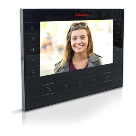
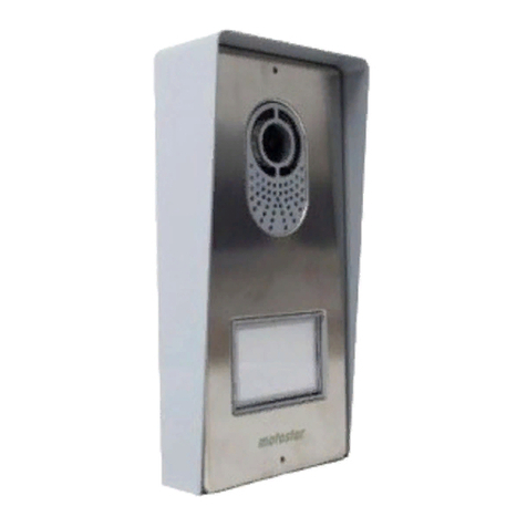
Motostar LIVIMN-B User manual

ITALY
MADE IN
W
A
R
R
A
N
T
Y
•
G
A
R
A
N
T
I
E
•
G
A
R
A
N
Z
I
A
•
G
A
R
A
N
T
I
A
•
G
A
R
A
N
T
I
E
•
G
A
R
A
N
T
I
E
•
Y
E
A
R
S
•
A
N
S
•
A
N
N
I
•
A
Ñ
O
S
•
A
N
O
•
J
A
H
R
E
•
3
FG00904M07- ver. 1- 07/2017
VIDEO
ENTRY PANEL
English
Français
Italiano
Español
Português
Deutsch
Türk
LIVIMN-B
LIVIMN-N
INSTALLATION MANUAL

212
161
29
60
83,5
83,5
A
B
CL.RES
M/S
LOCAL
SW1 SW3
SW4
M1
BUS
C
CL.RES CL.RES CL.RES
XDV/304
1 2 3
A
2
Page 2- Manual FG00904M07 - vers. 1- 07/2017- The contents of this manual may be changed, at any time, and without notice.
General warnings
• Important personal safety instructions: READ CAREFULLY!
• Installation, programming, commissioning and maintenance must only be performed by qualified and experienced personnel
in compliance with applicable regulations.
• Wear antistatic shoes and clothing if working on the control board.
• Keep hold of these warnings.
• Always disconnect the electrical power supply during cleaning or maintenance.
• This product should only be used for the purpose for which it was explicitly designed.Any other use is considered dangerous.
• The manufacturer declines all liability for any damage as a result of improper, incorrect or unreasonable use.
Description
Video receiver powered from BUS.
Terminal board A
+ – Local power supply
BBUS line input
–+Doorbell
AL Alarm input
Power supply source selector switch (BUS/LOCAL) B
A Position of link with locally powered device
2 Position of link with device powered from BUS
Closing resistance (CL.RES) C
The link should be inserted in the last device in the line only.

D
MASTER SLAVE
M/S M/S
2
1
E
F
G H
Page 3- Manual FG00904M07 - vers. 1- 07/2017- The contents of this manual may be changed, at any time, and without notice.
Master/Slave selector switch (M/S) D
If two or more receivers have been set up to respond to the
same call, the preview image of the caller is shown only on
the master receiver(s).
Technical data
Type
LIVIMN-B
LIVIMN-N
Power supply from BUS (VDC)
15÷20
Consumption (mA max)
410
Consumption in stand-by mode (mA)
<1
Local power supply (VDC)
16-18
Consumption (mA max)
370
Consumption of single LED (mA) (pan-
ic alarm, disabling ringtone)
1
Storage temperature (°C)
-25 to +70
Operating temperature (°C)
0 to +35
IP Rating
20
Video standard
PAL/NTSC
LCD TFT colour display (inches)
7
Installation
Install the device at a suitable height for the user.
• EPress button 1; unhook the bracket from the device by
sliding it along 2.
• Fasten the bracket to the recessed box:
round Ø 60mm For rectangular 503 GH. Use the screws
provided, follow the direction marked “TOP” and avoid over-
tightening the screws.

I
K
J
1
Page 4- Manual FG00904M07 - vers. 1- 07/2017- The contents of this manual may be changed, at any time, and without notice.
• Make the connections and fit the device onto the bracket
IJ.
• To unhook the unit from the bracket, press the button and
lift the device K.
For recessed installation refer to the recessing kit manual.

B
C
F
4
G
E
H
I
A
x5
Page 5- Manual FG00904M07 - vers. 1- 07/2017- The contents of this manual may be changed, at any time, and without notice.
Setting melodies
☞All the programming stages described below must be carried out in sequence:
1- Going into Programming.
Press button 5 times in 5 secs 1.
A short beep confirms that you have entered programming mode.
2- Programming the melody associated with a call from the entry panel.
To listen to the melodies in sequence, press key 2.
To select the melody and exit programming, press key 3.
To select the melody and continue with programming, press key 4.
3- Programming the melody associated with a call from the front door.
To listen to the melodies in sequence, press key 5.
To select the melody and exit programming, press key 6.
To select the melody and continue with programming, press key G.
4- Programming the number of rings for the call.
Press key 8 as many times as you want it to ring (from 1 to 6 rings). Three sec-
onds after the last press of the key the call selected for the chosen number of rings
will be played back.
To exit programming, press key I.
☞See the entry panel documentation for call programming.

L
La
MAX 8
Lb
LIVIPR
LIVI-AS
La
LIVI-AS LIVI-ASLIVI-AS
VCM/1D UTP/CAT 5 2x2,5mm2
La ≤100 m ≤30 m
≤100 m A–
Lb ≤25 m – ≤60 m
La + Lb ≤150 m
A
Page 6- Manual FG00904M07 - vers. 1- 07/2017- The contents of this manual may be changed, at any time, and without notice.
Installation diagrams
LLimits and distances with local power supply
A Devices powered locally.

M
La
La
N° Master N° Slave
Lb
LIVIPR
LIVI-AS
VCM/1D UTP/CAT 5 2x2,5mm2
La ≤100 m ≤30 m –
Lb ≤25 m – ≤60 m
La + Lb ≤150 m
VCM/1D UTP CAT5
N° Master 1 1
N° Slave 4 1
Page 7- Manual FG00904M07 - vers. 1- 07/2017- The contents of this manual may be changed, at any time, and without notice.
Installation diagrams
MLimits and distances with power supply from BUS

www.motostar-smarthome.com
contact@motostar-smarthome.com
è un marchio registrato di
Label Habitat SaS - 10 rue Léo Lagrange - 27950 Saint Marcel - France
Page 8- Manual FG00904M07 - vers. 1- 07/2017- The contents of this manual may be changed, at any time, and without notice.
This product complies with the relevant directives in force.
Decommissioning and disposal. Dispose of the packaging and the device at the end of its life cycle responsibly, in compliance
with the laws in force in the country where the product is used. The recyclable components are marked with a symbol and the
material's ID marker.
THE DATA AND INFORMATION SHOWN IN THIS MANUAL ARE TO BE CONSIDERED AS SUBJECT TO CHANGE AT ANY TIME AND WITHOUT THE NEED FOR ANY ADVANCE
WARNING. MEASUREMENTS, UNLESS OTHERWISE INDICATED, ARE IN MILLIMETRES.

ITALY
MADE IN
W
A
R
R
A
N
T
Y
•
G
A
R
A
N
T
I
E
•
G
A
R
A
N
Z
I
A
•
G
A
R
A
N
T
I
A
•
G
A
R
A
N
T
I
E
•
G
A
R
A
N
T
I
E
•
Y
E
A
R
S
•
A
N
S
•
A
N
N
I
•
A
Ñ
O
S
•
A
N
O
•
J
A
H
R
E
•
3
FG00904M07- ver. 1- 07/2017
PORTIER VIDÉO
EXTERNE
English
Français
Italiano
Español
Português
Deutsch
Türk
LIVIMN-B
LIVIMN-N
MANUEL D'INSTALLATION

212
161
29
60
83,5
83,5
A
B
CL.RES
M/S
LOCAL
SW1 SW3
SW4
M1
BUS
C
CL.RES CL.RES CL.RES
XDV/304
1 2 3
A
2
Page 2- Manuel FG00904M07 - vers. 1- 07/2017- Le contenu de ce manuel est susceptible de subir des modifications à tout moment et sans aucun préavis.
Instructions générales
• Instructions importantes pour la sécurité des personnes : À LIRE ATTENTIVEMENT !
• L’installation, la programmation, la mise en service et l'entretien doivent être eectués par du personnel qualifié et dans le
plein respect des normes en vigueur.
• Porter des vêtements et des chaussures antistatiques avant d'intervenir sur la carte électronique.
• Conserver ces instructions.
• Toujours couper le courant électrique durant les opérations de nettoyage ou d'entretien.
• Ce produit ne devra être destiné qu'à l'utilisation pour laquelle il a été expressément conçu. Toute autre utilisation est à
considérer comme dangereuse.
• Le fabricant décline toute responsabilité en cas d'éventuels dommages provoqués par des utilisations impropres, incorrectes
et déraisonnables.
Description
Poste vidéophonique interne avec alimentation par BUS.
Bornier A
+ – Alimentation locale
BEntrée ligne BUS
–+Appel depuis palier
AL Entrée alarme
Sélecteur source d’alimentation (BUS/LOCAL) B
A Position du shunt avec dispositif alimenté localement
2 Position du shunt avec dispositif alimenté par BUS
Résistance de terminaison de ligne (CL.RES) C
Le shunt ne doit être activé que dans le dernier dispositif de
la ligne.

D
MASTER SLAVE
M/S M/S
2
1
E
F
G H
Page 3- Manuel FG00904M07- vers. 1- 07/2017- Le contenu de ce manuel est susceptible de subir des modifications à tout moment et sans aucun préavis.
Sélecteur maître/esclave (M/S) D
Si un ou plusieurs postes internes ont été configurés pour ré-
pondre à un même appel, l’aperçu de l’image de l’appelant ne
sera visualisé que sur le/les poste/s interne/s maître/s.
Données techniques
Type LIVIMN-B
LIVIMN-N
Alimentation par BUS (VDC) 15 - 20
Absorption (mA max.) 410
Absorption en mode veille (mA) <1
Alimentation locale (VDC) 16 - 18
Absorption (mA max.) 370
Absorption LED simple (mA) (panique,
désactivation sonnerie) 1
Température de stockage (°C) -25 à +70
Température de fonctionnement (°C)
0 à +35
Degré IP 20
Standard vidéo PAL/NTSC
Écran LCD TFT couleur (pouces)
7
Installation
Installer le dispositif à la hauteur convenant à l’utilisateur.
• EAppuyer sur le bouton 1; décrocher le support du dis-
positif en le faisant glisser 2.
• Fixer le support au boîtier à encastrer :
rond Ø 60mm Fou rectangulaire 503 GH. Utiliser les vis
fournies sans trop les serrer et respecter l’indication TOP.

I
K
J
1
Page 4- Manuel FG00904M07 - vers. 1- 07/2017- Le contenu de ce manuel est susceptible de subir des modifications à tout moment et sans aucun préavis.
• Eectuer les branchements et fixer le dispositif au support
IJ.
• Pour décrocher l’appareil du support, appuyer sur le bouton
et soulever le dispositif K.
Pour la version à encastrer, se référer au manuel du kit à en-
castrer.

B
C
F
4
G
E
H
I
A
x5
Page 5- Manuel FG00904M07- vers. 1- 07/2017- Le contenu de ce manuel est susceptible de subir des modifications à tout moment et sans aucun préavis.
Configuration des mélodies
☞Eectuer, l’une après l’autre, toutes les phases de programmation décrites ci-
après :
1- Entrée en mode programmation.
Appuyer 5 fois sur le bouton en 5 s 1.
Un signal sonore bref confirme l’entrée en mode programmation.
2- Programmation de la mélodie associée à l’appel provenant du poste externe.
Pour écouter les mélodies l’une après l’autre, appuyer sur la touche 2.
Pour sélectionner la mélodie et sortir de la programmation, appuyer sur la touche
3.
Pour sélectionner la mélodie et poursuivre la programmation, appuyer sur la touche
4.
3- Programmation de la mélodie associée à l’appel provenant du palier.
Pour écouter les mélodies l’une après l’autre, appuyer sur la touche 5.
Pour sélectionner la mélodie et sortir de la programmation, appuyer sur la touche
6.
Pour sélectionner la mélodie et poursuivre la programmation, appuyer sur la touche
G.
4- Programmation du nombre de sonneries de l’appel.
Appuyer sur la touche 8 autant de fois que le nombre de sonneries souhaité (de
1 à 6 sonneries). Au bout de 3 secondes à compter du dernier enfoncement de la
touche, l’appel sélectionné sera reproduit selon le nombre de sonneries choisi.
Pour sortir du menu de programmation, appuyer sur la touche I.
☞Pour la programmation de l’appel, voir la documentation des postes externes.

L
La
MAX 8
Lb
LIVIPR
LIVI-AS
La
LIVI-AS LIVI-ASLIVI-AS
VCM/1D UTP/CAT 5 2x2,5mm2
La ≤100 m ≤30 m
≤100 m A–
Lb ≤25 m – ≤60 m
La + Lb ≤150 m
A
Page 6- Manuel FG00904M07 - vers. 1- 07/2017- Le contenu de ce manuel est susceptible de subir des modifications à tout moment et sans aucun préavis.
Schémas d'installation
LLimites et distances avec alimentation locale
A Dispositifs alimentés localement.

M
La
La
N° Master N° Slave
Lb
LIVIPR
LIVI-AS
VCM/1D UTP/CAT 5 2x2,5mm2
La ≤100 m ≤30 m –
Lb ≤25 m – ≤60 m
La + Lb ≤150 m
VCM/1D UTP CAT5
N° Master 1 1
N° Slave 4 1
Page 7- Manuel FG00904M07- vers. 1- 07/2017- Le contenu de ce manuel est susceptible de subir des modifications à tout moment et sans aucun préavis.
Schémas d'installation
MLimites et distances avec alimentation par BUS

www.motostar-smarthome.com
contact@motostar-smarthome.com
è un marchio registrato di
Label Habitat SaS - 10 rue Léo Lagrange - 27950 Saint Marcel - France
Page 8- Manuel FG00904M07- vers. 1- 07/2017- Le contenu de ce manuel est susceptible de subir des modifications à tout moment et sans aucun préavis.
Ce produit est conforme aux directives de référence en vigueur.
Mise au rebut et élimination. Ne pas jeter l'emballage et le dispositif dans la nature au terme du cycle de vie de ce dernier,
mais les éliminer selon les normes en vigueur dans le pays où le produit est utilisé. Le symbole et le sigle du matériau figurent
sur les composants recyclables.
LES DONNÉES ET LES INFORMATIONS CONTENUES DANS CE MANUEL SONT SUSCEPTIBLES DE SUBIR DES MODIFICATIONS À TOUT MOMENT ET SANS AUCUN PRÉAVIS.
LES DIMENSIONS SONT EXPRIMÉES EN MILLIMÈTRES, SAUF INDICATION CONTRAIRE.

ITALY
MADE IN
W
A
R
R
A
N
T
Y
•
G
A
R
A
N
T
I
E
•
G
A
R
A
N
Z
I
A
•
G
A
R
A
N
T
I
A
•
G
A
R
A
N
T
I
E
•
G
A
R
A
N
T
I
E
•
Y
E
A
R
S
•
A
N
S
•
A
N
N
I
•
A
Ñ
O
S
•
A
N
O
•
J
A
H
R
E
•
3
FG00904M07- ver. 1- 07/2017
POSTO ESTERNO
VIDEOCITOFONICO
English
Français
Italiano
Español
Português
Deutsch
Türk
LIVIMN-B
LIVIMN-N
MANUALE DI INSTALLAZIONE
Pag. TM - Manuale FG00904M07- ver. 1- 07/2017 - I contenuti del manuale sono da ritenersi suscettibili di modifica in qualsiasi momento senza obbligo di preavviso.

212
161
29
60
83,5
83,5
A
B
CL.RES
M/S
LOCAL
SW1 SW3
SW4
M1
BUS
C
CL.RES CL.RES CL.RES
XDV/304
1 2 3
A
2
Pag. 2- Manuale FG00904M07 - ver. 1- 07/2017- I contenuti del manuale sono da ritenersi suscettibili di modifica in qualsiasi momento senza obbligo di preavviso.
Avvertenze generali
• Importanti istruzioni per la sicurezza delle persone: LEGGERE ATTENTAMENTE!
• L’installazione, la programmazione, la messa in servizio e la manutenzione devono essere eettuate da personale qualificato
ed esperto e nel pieno rispetto delle normative vigenti.
• Indossare indumenti e calzature antistatiche nel caso di intervento sulla scheda elettronica.
• Conservare queste avvertenze.
• Togliere sempre l’alimentazione elettrica durante le operazioni di pulizia o di manutenzione.
• Il prodotto deve essere destinato solo all’uso per il quale è stato espressamente studiato. Ogni altro uso è da considerarsi
pericoloso.
• Il costruttore non può comunque essere considerato responsabile per eventuali danni derivanti da usi impropri, erronei ed
irragionevoli.
Descrizione
Derivato interno videocitofonico con alimentazione da BUS.
Morsettiera A
+ – Alimentazione locale
BIngresso linea BUS
–+Chiamata da pianerottolo
AL Ingresso allarme
Selettore fonte di alimentazione (BUS/LOCAL) B
A Posizione del ponticello con dispositivo alimentato local-
mente
2 Posizione del ponticello con dispositivo alimentato da BUS
Resistenza di fine linea (CL.RES) C
Il ponticello deve essere inserito solo nell'ultimo dispositivo
della linea.

D
MASTER SLAVE
M/S M/S
2
1
E
F
G H
Pag. 3- Manuale FG00904M07 - ver. 1- 07/2017- I contenuti del manuale sono da ritenersi suscettibili di modifica in qualsiasi momento senza obbligo di preavviso.
Selettore master/slave (M/S) D
Se duo o più derivati sono stati configurati per rispondere ad
una stessa chiamata, solo sul/sui derivati master viene visua-
lizzata l'immagine in anteprima del chiamante.
Dati tecnici
Tipo
LIVIMN-B
LIVIMN-N
Alimentazione da BUS (VDC)
15÷20
Assorbimento (mA max)
410
Assorbimento in stand by (mA)
<1
Alimentazione locale (VDC)
16÷18
Assorbimento (mA max)
370
Assorbimento singolo LED (mA) (panico, esclu-
sione suoneria)
1
Temperatura di stoccaggio (°C)
-25 ÷ +70
Temperatura di funzionamento (°C)
0 ÷ +35
Grado IP
20
Standard video
PAL/NTSC
Display LCD TFT a colori (pollici)
7
Installazione
Installare il dispositivo ad un’altezza adeguata all’utente.
• E Premere il pulsante 1; sganciare il supporto dal disposi-
tivo facendolo scorrere 2.
• Fissare il supporto alla scatola da incasso:
tonda Ø 60mm Foppure rettangolare 503 GH. Utilizzare
le viti in dotazione, rispettare l’indicazione TOP ed evitare il
serraggio eccessivo delle viti.

I
K
J
1
Pag. 4- Manuale FG00904M07 - ver. 1- 07/2017- I contenuti del manuale sono da ritenersi suscettibili di modifica in qualsiasi momento senza obbligo di preavviso.
• Eseguire i collegamenti e agganciare il dispositivo al sup-
porto IJ.
• Per sganciare l’apparecchio dal supporto premere il pulsan-
te e sollevare il dispositivo K.
Per l’installazione da incasso fare riferimento al manuale del
kit da incasso.
Other manuals for LIVIMN-B
1
This manual suits for next models
1
Table of contents
Languages:
Other Motostar Intercom System manuals