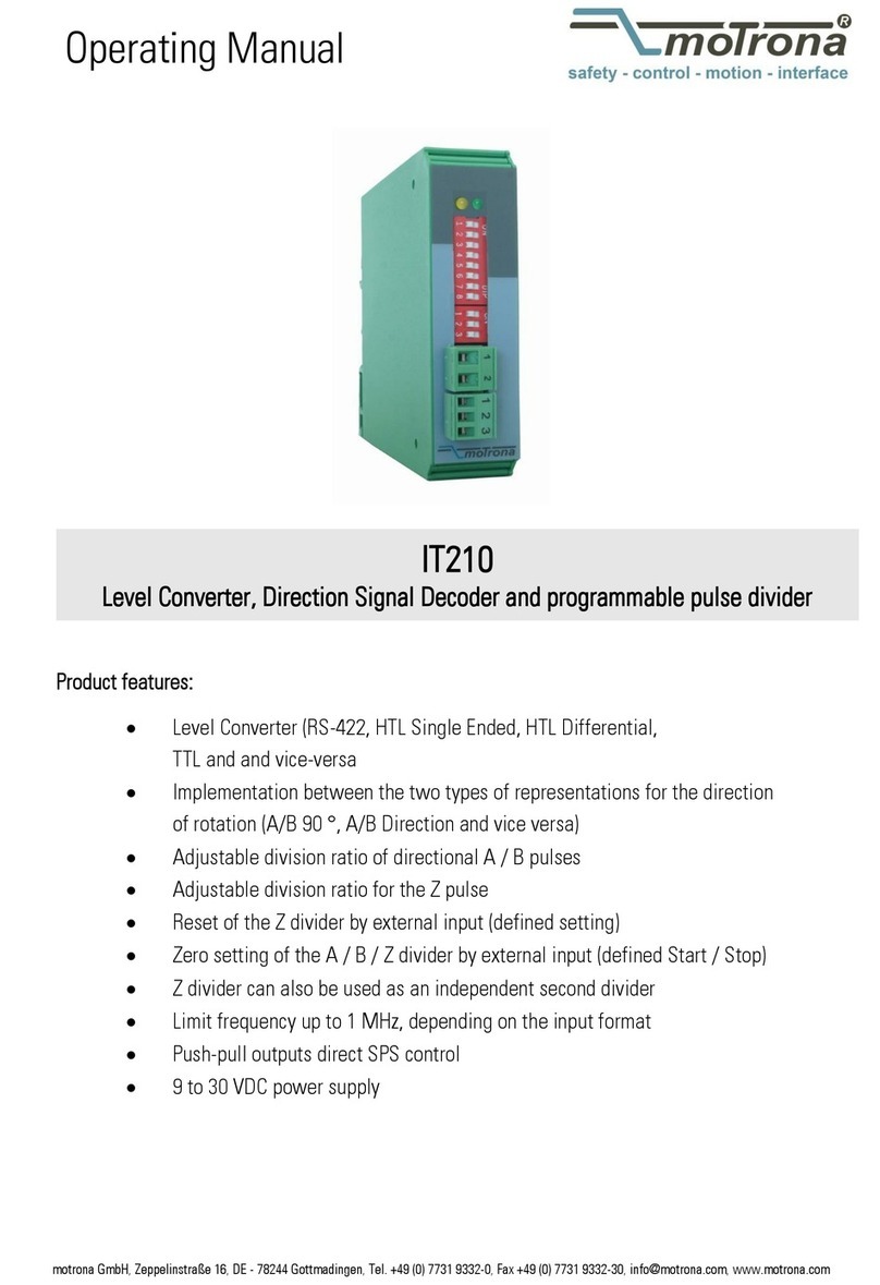
Motrona SV211 User manual
Other Motrona Media Converter manuals
Motrona
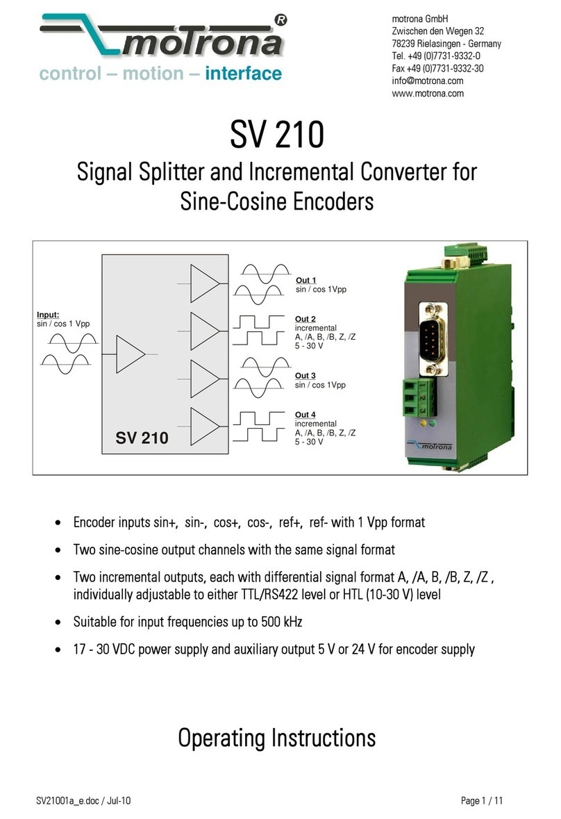
Motrona SV 210 User manual

Motrona
Motrona UF251 User manual

Motrona
Motrona FM210 User manual
Motrona
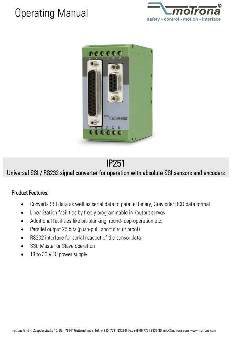
Motrona IP251 User manual

Motrona
Motrona IO220 User manual

Motrona
Motrona PU202 User manual
Motrona
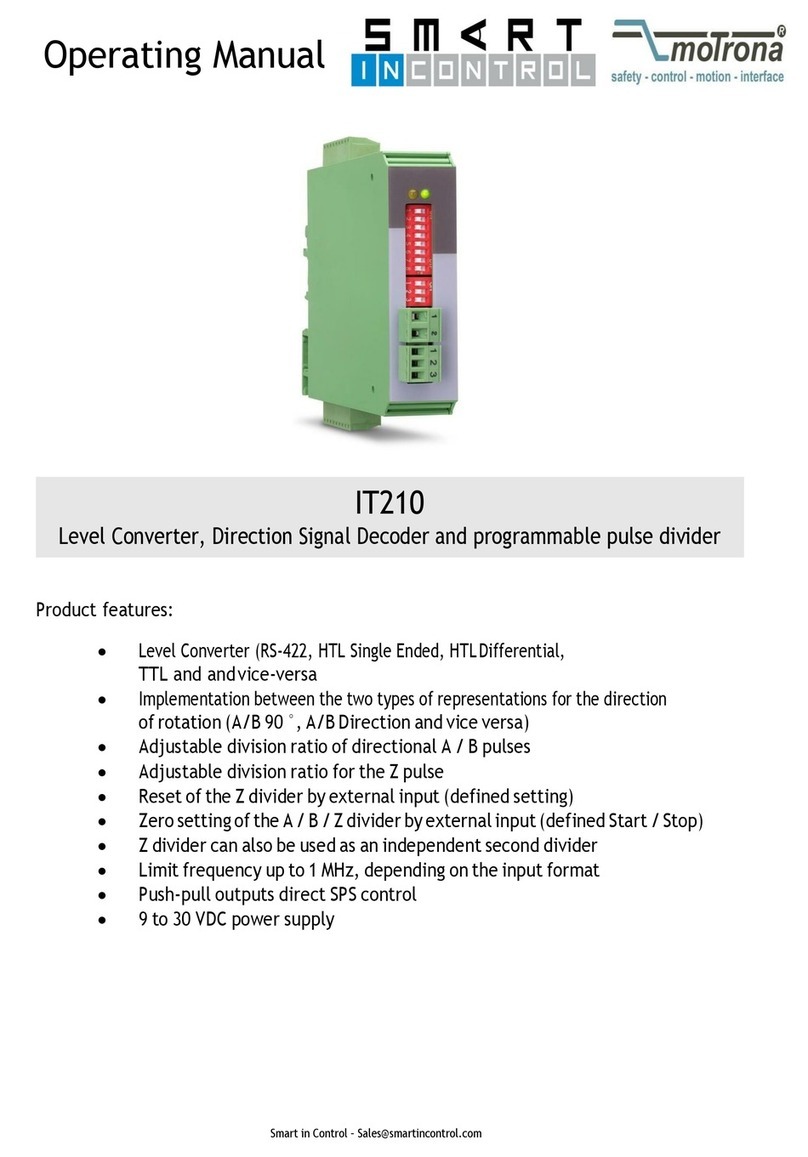
Motrona IT210 User manual

Motrona
Motrona IV 251 User manual
Motrona
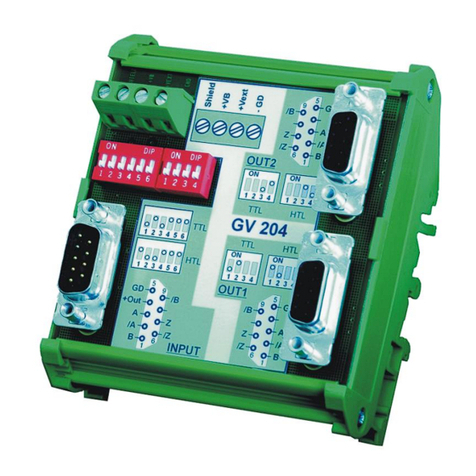
Motrona GV204 User manual

Motrona
Motrona ES001 User manual

Motrona
Motrona GV210 User manual

Motrona
Motrona SI 251 User manual

Motrona
Motrona PU 210 User manual

Motrona
Motrona UZ210 User manual
Motrona
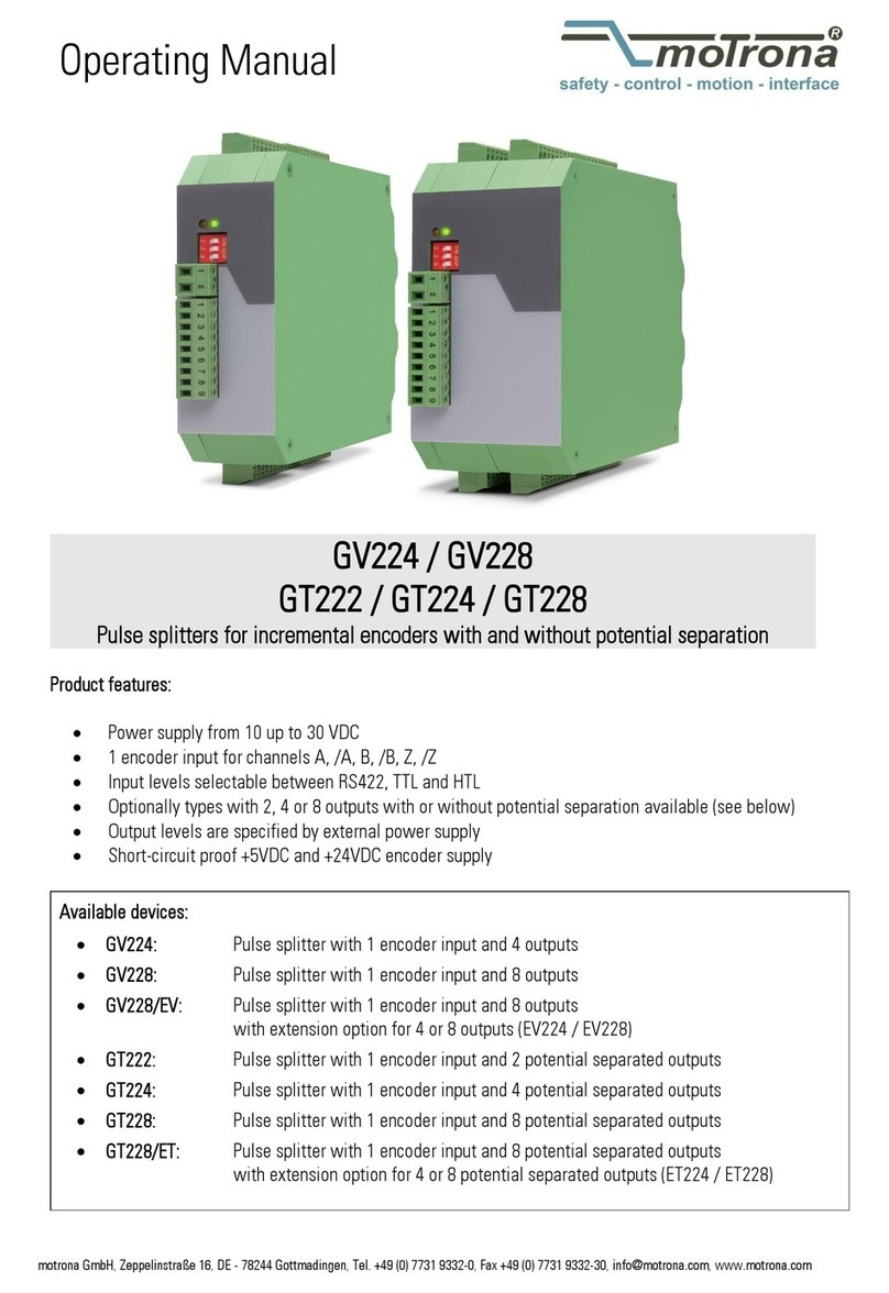
Motrona GV224 User manual
Motrona
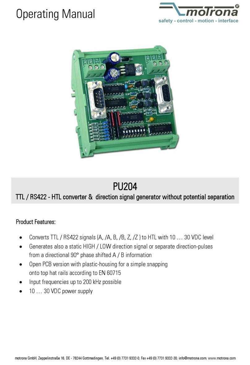
Motrona PU 204 User manual

Motrona
Motrona PU 204 User manual
Motrona
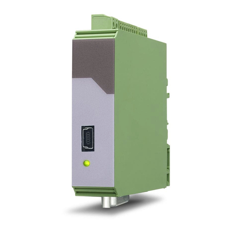
Motrona FP210 User manual

Motrona
Motrona IT251 User manual
Motrona
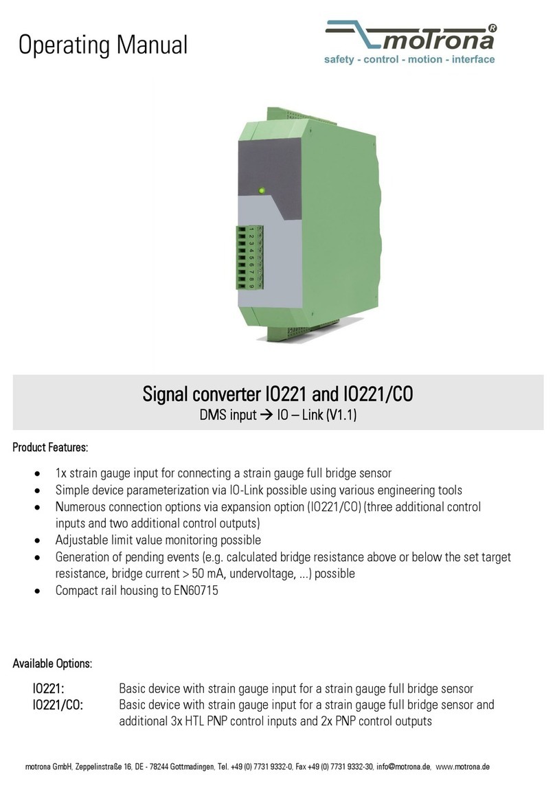
Motrona IO221 User manual
Popular Media Converter manuals by other brands

H&B
H&B TX-100 Installation and instruction manual

Bolin Technology
Bolin Technology D Series user manual

IFM Electronic
IFM Electronic Efector 400 RN30 Series Device manual

GRASS VALLEY
GRASS VALLEY KUDOSPRO ULC2000 user manual

Linear Technology
Linear Technology DC1523A Demo Manual

Lika
Lika ROTAPULS I28 Series quick start guide

Weidmuller
Weidmuller IE-MC-VL Series Hardware installation guide

Optical Systems Design
Optical Systems Design OSD2139 Series Operator's manual

Tema Telecomunicazioni
Tema Telecomunicazioni AD615/S product manual

KTI Networks
KTI Networks KGC-352 Series installation guide

Gira
Gira 0588 Series operating instructions

Lika
Lika SFA-5000-FD user guide
