Motrona IO221 User manual

Operating Manual
motrona GmbH, Zeppelinstraße 16, DE - 78244 Gottmadingen, Tel. +49 (0) 7731 9332-0, Fax +49 (0) 7731 9332-30, [email protected], www.motrona.de
Signal converter IO221 and IO221/CO
DMS input →IO –Link (V1.1)
Product Features:
•1x strain gauge input for connecting a strain gauge full bridge sensor
•Simple device parameterization via IO-Link possible using various engineering tools
•Numerous connection options via expansion option (IO221/CO) (three additional control
inputs and two additional control outputs)
•Adjustable limit value monitoring possible
•Generation of pending events (e.g. calculated bridge resistance above or below the set target
resistance, bridge current > 50 mA, undervoltage, ...) possible
•Compact rail housing to EN60715
Available Options:
IO221: Basic device with strain gauge input for a strain gauge full bridge sensor
IO221/CO: Basic device with strain gauge input for a strain gauge full bridge sensor and
additional 3x HTL PNP control inputs and 2x PNP control outputs

Io221_01a_oi_e.docx / Jul-23 Seite 2 / 42
Die deutsche Beschreibung ist verfügbar unter:
https://www.motrona.com/fileadmin/files/bedienungsanleitungen/Io221_d.pdf
The English description is available at:
https://www.motrona.com/fileadmin/files/bedienungsanleitungen/Io221_e.pdf
La description en français est disponible sur:
https://www.motrona.com/fileadmin/files/bedienungsanleitungen/Io221_f.pdf
The operator software OS (freeware) is available at:
https://www.motrona.com/en/support/software.html
Version:
Beschreibung:
Io221_01a_oi/tgo/July-23
First Version
Legal notices:
All contents included in this manual are protected by the terms of use and copyrights of motrona
GmbH. Any reproduction, modification, usage or publication in other electronic and printed media
as well as in the internet requires prior written authorization by motrona GmbH.

Io221_01a_oi_e.docx / Jul-23 Seite 3 / 42
Inhaltsverzeichnis
Safety Instructions and Responsibility.......................................................................... 5
General Safety Instructions.............................................................................................................5
Use according to the intended purpose ..........................................................................................5
Installation .......................................................................................................................................6
EMC Guidelines ...............................................................................................................................7
Cleaning, Maintenance and Service Notes.....................................................................................7
Introduction.................................................................................................................. 8
Function diagram .............................................................................................................................9
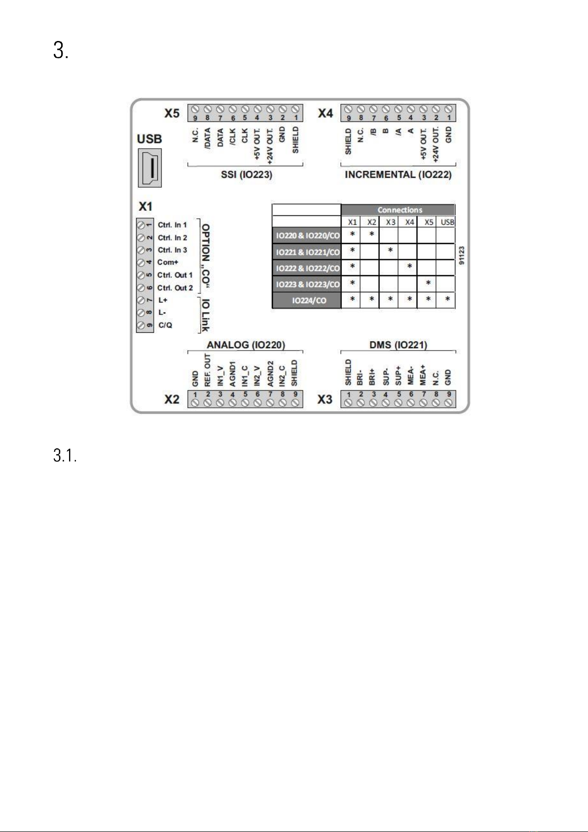
Electrical Connections................................................................................................ 10
DC Power Supply ...........................................................................................................................10
DMS Input......................................................................................................................................11
Control Inputs (only with option „CO“)..........................................................................................12
Control Outputs (only with option „CO“).......................................................................................13
IO-Link Interface.............................................................................................................................14
Usable IO Link masters.........................................................................................................................14
Communication data.............................................................................................................................14
Features ................................................................................................................................................14
Front LED...............................................................................................................................................14
Connection of the IO Link interface......................................................................................................15
Parameter data .....................................................................................................................................15
System Kommandos .............................................................................................................................18
IO-Link Process data .............................................................................................................................19
Error types.............................................................................................................................................20
Events....................................................................................................................................................21
Parameter / Overview - Menu Structure..................................................................... 22
Sensor Menu..................................................................................................................................23
Digital Input Menu.........................................................................................................................25
Digital Output Menu ......................................................................................................................26
General Menu ................................................................................................................................30
Adjustment Menu ..........................................................................................................................31
Commissioning........................................................................................................... 33
Basic setting oft he strain gauge sensor.......................................................................................33
Easiest setting ...............................................................................................................................34
Conversion to sensor units ............................................................................................................35
Digtal Input ....................................................................................................................................36
Digital Output.................................................................................................................................36
Other optional settings ..................................................................................................................36
Examination of the analog read in values............................................................................................36
Calibration of the MEA readback ..................................................................................................37
Calibration of analog input BRI / DMS..........................................................................................37
Input stage calibration..........................................................................................................................37
Calibration of the input stage and the DMS sensor............................................................................38
Monitor codes for calibration...............................................................................................................38
Attachment ................................................................................................................ 39
Parameter / serial codes................................................................................................................39

Io221_01a_oi_e.docx / Jul-23 Seite 4 / 42
Dimensions ....................................................................................................................................41
Technical Specifications................................................................................................................42

Io221_01a_oi_e.docx / Jul-23 Seite 5 / 42
Safety Instructions and Responsibility
General Safety Instructions
This operation manual is a significant component of the unit and includes important rules and hints
about the installation, function and usage. Non-observance can result in damage and/or impairment
of the functions to the unit or the machine or even in injury to persons using the equipment!
Please read the following instructions carefully before operating the device and observe all safety
and warning instructions! Keep the manual for later use.
A pertinent qualification of the respective staff is a fundamental requirement in order to use this
manual. The unit must be installed, connected and put into operation by a qualified electrician.
Liability exclusion: The manufacturer is not liable for personal injury and/or damage to property and
for consequential damage, due to incorrect handling, installation and operation. Further claims, due to
errors in the operation manual as well as misinterpretations are excluded from liability.
In addition, the manufacturer reserves the right to modify the hardware, software or operation manual
at any time and without prior notice. Therefore, there might be minor differences between the unit
and the descriptions in operation manual.
The raiser respectively positioner is exclusively responsible for the safety of the system and
equipment where the unit will be integrated.
During installation or maintenance all general and also all country- and application-specific safety
rules and standards must be observed.
If the device is used in processes, where a failure or faulty operation could damage the system or
injure persons, appropriate precautions to avoid such consequences must be taken.
Use according to the intended purpose
The unit is intended exclusively for use in industrial machines, constructions and systems. Non-
conforming usage does not correspond to the provisions and lies within the sole responsibility of the
user. The manufacturer is not liable for damages which have arisen through unsuitable and improper
use.
Please note that device may only be installed in proper form and used in a technically perfect
condition (in accordance to the Technical Specifications). The device is not suitable for operation in
explosion-proof areas or areas which are excluded by the EN 61010-1 standard.

Io221_01a_oi_e.docx / Jul-23 Seite 6 / 42
Installation
The device is only allowed to be installed and operated within the permissible temperature range.
Please ensure an adequate ventilation and avoid all direct contact between the device and hot or
aggressive gases and liquids.
Before installation or maintenance, the unit must be disconnected from all voltage-sources. Further it
must be ensured that no danger can arise by touching the disconnected voltage-sources.
Devices which are supplied by AC-voltages must be connected exclusively by switches, respectively
circuit-breakers with the low voltage network. The switch or circuit-breaker must be placed as near as
possible to the device and further indicated as separator.
Incoming as well as outgoing wires and wires for extra low voltages (ELV) must be separated from
dangerous electrical cables (SELV circuits) by using a double resp. increased isolation.
All selected wires and isolations must be conformed to the provided voltage- and temperature-ranges.
Further all country- and application-specific standards, which are relevant for structure, form and
quality of the wires, must be ensured. Indications about the permissible wire cross-sections for wiring
are described in the Technical Specifications.
Before first start-up it must be ensured that all connections and wires are firmly seated and secured
in the screw terminals. All (inclusively unused) terminals must be fastened by turning the relevant
screws clockwise up to the stop.
Overvoltages at the connections must be limited to values in accordance to the overvoltage
category II.

Io221_01a_oi_e.docx / Jul-23 Seite 7 / 42
EMC Guidelines
All motrona devices are designed to provide high protection against electromagnetic interference.
Nevertheless you must minimize the influence of electromagnetic noise to the device and all connected
cables.
Therefore the following measures are mandatory for a successful installation and operation:
•Use shielded cables for all signal and control input and output lines.
•Cables for digital controls (digital I/O, relay outputs) must not exceed a length of 30 m and are
allowed for in building operation only
•Use shield connection clamps to connect the cable shields properly to earth
•The wiring of the common ground lines must be star-shaped and common ground must be
connected to earth at only one single point
•The device should be mounted in a metal enclosure with sufficient distance to sources of
electromagnetic noise.
•Run signal and control cables apart from power lines and other cables emitting electromagnetic
noise.
Please also refer to motrona manual “General Rules for Cabling, Grounding, Cabinet Assembly”. You can
download that manual by the link
https://www.motrona.com/en/support/general-certificates.html
Cleaning, Maintenance and Service Notes
To clean the front of the unit please use only a slightly damp (not wet!), soft cloth. For the rear no
cleaning is necessary. For an unscheduled, individual cleaning of the rear the maintenance staff or
assembler is self-responsible.
During normal operation no maintenance is necessary. In case of unexpected problems, failures or
malfunctions the device must be shipped for back to the manufacturer for checking, adjustment and
reparation (if necessary). Unauthorized opening and repairing can have negative effects or failures to
the protection-measures of the unit.

Io221_01a_oi_e.docx / Jul-23 Seite 8 / 42
Introduction
The IO221 or the IO221/CO are devices for connecting a strain gauge full bridge sensor, the converted
measurement result of which is transmitted cyclically via the process data via IO Link. The "CO"
expansion option also has three HTL PNP control inputs and two PNP switching outputs. These
switching outputs transmit when switching points are exceeded or fallen below, as well as
movements outside of a range. A DMS error can also be signaled. With the help of "System
Commands" via IO-Link or via one of the three additional HTL Control inputs, a zero setting of the
strain gauge sensor can be triggered or the self-locking on the outputs can be withdrawn. The status
of the control inputs and outputs as well as relevant diagnostic information are also transmitted
cyclically with the process data. In addition, any pending events (e.g. calculated bridge resistance
above or below the set target resistance, bridge current > 50 mA, undervoltage, ... ) can be generated
if this is desired by the user. The individual device parameters can be set and saved using various
engineering tools or during operation via IO-Link. Thanks to the supported "data storage" mechanism,
an uncomplicated and problem-free exchange of devices is possible at any time.

Io221_01a_oi_e.docx / Jul-23 Seite 9 / 42
Function diagram

Io221_01a_oi_e.docx / Jul-23 Seite 10 / 42
Electrical Connections
The terminal screws should be tightened with a slotted screwdriver (blade width 2mm).
DC Power Supply
The unit accepts DC supply from 18 to 30 V at the terminals X1 pin 7 (+) und 8 (-). The power
consumption depends on the level of the supply voltage with approx. 75 mA (at 24V).
All GND terminals are internally interconnected.

Io221_01a_oi_e.docx / Jul-23 Seite 11 / 42
DMS Input
Strain gauge full bridge supply
With the terminals SUP+, SUP- resp. X3 Pin 5 (+) and Pin 4 (-) the DMS sensor can be supplied by a
programmable voltage of 3V - 10VDC with max. 50mA. The supply voltage can be read back in mV via
Index „40“, Subindex „19“
DMS full bridge readback
With the terminals MEA+, MEA- resp. X3 Pin 7 (+) and Pin 6 (-) the DMS sensor supply voltage can be
read back. These terminals must be connected in any case, ideally directly at the full bridge, in order
to avoid voltage drops at the supply line.
DMS full bridge voltage
With the terminals BRI+, BRI- resp. X3 Pin 3 (+) and Pin 2 (-) the DMS bridge voltage can be evaluated.
The bridge voltage in units can be read back via „Index 40“, Subindex „21“
Connection example DMS sensor
The picture below shows an example of how to connect a strain gauge sensor. (SUP = Supply, MEA =
Measurement of Supply, BRI = Bridge Voltage)

Io221_01a_oi_e.docx / Jul-23 Seite 12 / 42
Control Inputs (only with option „CO“)
Three control inputs with HTL PNP characteristics are available on terminal X1, pins 1, 2 and 3. The
current state of the control inputs is cyclically exchanged with the process data and can therefore be
used for a wide variety of functions. (e.g. as a trigger signal to trigger a "system command" or to read
out current actual values via the PLC). The respective input can also be configured with a fixed
function (“INPUT x FUNCTION”) via the “DIGITAL INPUT MENU”. (e.g. "Tara" of the DMS input)
Connection of the control inputs:
Unconnected control inputs are always “LOW”.
All inputs are designed to receive impulses from an electronic impulse source.
Notice for mechanical switching contacts:
When exceptionally mechanical contacts are used, please connect an external
capacitor between GND (-) and the corresponding input (+). A capacity of 10 µF will
reduce the input frequency to
20 Hz and miscounting due to contact bouncing will be eliminated.

Io221_01a_oi_e.docx / Jul-23 Seite 13 / 42
Control Outputs (only with option „CO“)
Two control outputs are available on terminal X1, pins 5 and 6. Depending on the configuration
("DIGITAL OUTPUT MENU"), they can transmit different statuses.
The outputs Ctrl. Out 1 and 2 are designed as high side drivers. The status of the outputs is
transmitted cyclically with the IO-Link process data.
The switching voltage is determined by the external voltage supplied to terminal X1 pin 4 (COM+).
External damping measures are recommended for switching inductive loads.
Connection of the control outputs:

Io221_01a_oi_e.docx / Jul-23 Seite 14 / 42
IO-Link Interface
This chapter contains important notes and information regarding IO-Link communication data. In
addition to general information on the IO-Link connection, the parameter data of the device, the
exchanged process data and the implemented system commands, error codes and events are
discussed.
Usable IO Link masters
All IO-Link masters that support IO-Link Standard V1.1.
Communication data
Parameters
Values
Communication speed
COM 3
Transmission rate
230,4 kbit/s
IO-Link Revision
V1.1
Cycle time
min. 1 ms
Port class
Class A
Features
Feature
Unterstützt
Block parametrization
Yes
Data Storage
Yes
Events
Yes
SIO Mode
No
Front LED
In the case of devices without the "CO" option, the green LED on the front is used exclusively as a
ready-to-operate display. As soon as a supply voltage has been applied to the device, it lights up
continuously.
For devices with the extended "CO" option, the green LED on the front serves as a ready-to-operate
display. It also signals the current IO-Link system status.
LED lights up continuously:
The device is connected to the supply voltage and there is no IO-Link communication.The device is in
"START UP MODE".
LED flashes at 0.5 Hz:
Device is connected to the supply voltage and IO-Link communication is currently in "PREOPERATE
MODE" (no cyclic data exchange takes place).
LED flashes at 1 Hz cycle:
The device is connected to the supply voltage and IO-Link communication is currently in "OPERATE
MODE" (cyclic data exchange is taking place).

Io221_01a_oi_e.docx / Jul-23 Seite 15 / 42
Connection of the IO Link interface
An interface for connecting to an IO-Link master port is available on terminal X1 pin 7 (L-), 8 (L+) and 9
(C/Q). Figure 1 shows the pin assignment of a standard M12 connector plug.
Assignment
Pin 1
Clamp L+
Pin 2
Not connected
Pin 3
Clamp L-
Pin 4
IO-Link data line, C/Q
Fig. 1: Pin assignement M12 connection plug
Pin
Wire color
1 (L+)
brown
2 (n.c.)
white
3 (L-)
blue
4 (C/Q)
black
Parameter data
ISDU
Index
DPP1
Index
Name of the Parameter
Access
Length
in bytes
Default Value
Range
Identification Menu
7
VendorID
R
2
980 / 0x 03D4
-
8
9
Device ID
R
3
2228481 / 0x220101
-
10
11
16
Vendor Name
R
12
motrona GmbH
-
17
Vendor Text
R
21
http://www.motrona.de
-
18
Product Name
R
16
signal amplifier
-
19
Product ID
R
8
IO221 oder IO221/CO
-
20
Product Text
R
36
DMS amplifier with IO-
Link interface
-
21
Serial Number
R
9
-
-
22
Hardware Revision
R
7
z.B.: 224IO11
-
23
Firmware Revision
R
8
z.B.: IO22101A
-
24
Application Specific Tag
R/W
Max. 32
***
-
36
Device Status
R
1
0x00
0: Device is working
properly
1: Maintenance
required
2: Out of
specification
3: Functional test
4: Error
5-255: Reserved
40
Prozess Data Input
R
16
-
-

Io221_01a_oi_e.docx / Jul-23 Seite 16 / 42
Continuation “Parameter data”:
ISDU
Index
DPP1
Index
Name of the Parameter
Access
Length
in bytes
Default Value
Range
SENSOR MENU
258
SENSOR SUPPLY
R/W
4
5
3..10
259
SENSOR GAIN
R/W
4
0
0..4
260
SENSOR OSR
R/W
4
0
0..12
261
SENSOR OFFSET
R/W
4
0
-10000..10000
262
SENSOR RESISTOR
R/W
4
350
0..10000
263
SENSOR SENSITIVITY
R/W
4
1000
100..20000
264
SENSOR VOLTAGE
R/W
4
1000
1..99999
265
SENSOR DIGIT
R/W
4
1000
1..99999
266
SENSOR CORRECTION
R/W
4
1000
900..1100
267
SENSOR POLARITY
R/W
4
0
0..1
DIGITAL INPUT MENU
272
INPUT 1 CONFIG
R/W
4
2
0..3
273
INPUT 1 FUNCTION
R/W
4
0
0..6
274
INPUT 2 CONFIG
R/W
4
2
0..3
275
INPUT 2 FUNCTION
R/W
4
0
0..6
276
INPUT 3 CONFIG
R/W
4
2
0..3
277
INPUT 3 FUNCTION
R/W
4
0
0..6
DIGITAL OUTPUT MENU
281
OUTPUT POLARITY
R/W
4
0
0..3
282
OUTPUT LOCK
R/W
4
0
0..3
283
OUTPUT SOURCE 1
R/W
4
0
0..1
284
OUTPUT FUNCTION 1
R/W
4
7
0..7
285
OUTPUT HYSTERESIS 1
R/W
4
0
0..9999
286
OUTPUT PRESELECTION 1
R/W
4
1000
-9999..9999
287
OUTPUT SOURCE 2
R/W
4
0
0..1
288
OUTPUT FUNCTION 2
R/W
4
7
0..7
289
OUTPUT HYSTERESIS 2
R/W
4
0
0..9999
290
OUTPUT PRESELECTION 2
R/W
4
1000
-9999..9999
GENERAL MENU
294
FILTER
R/W
4
0
0..9
295
MIN MAX CHANNEL
R/W
4
0
0..2
296
DIAGNOSIS SETUP
R/W
4
0 (0x00)
0x00..0x0F
ADJUSTMENT MENU
302
TCI BRIDGE OFFSET
R/W
4
10000
5000..15000
303
TCI BRIDGE GAIN
R/W
4
100000
90000..110000
304
TEMP. COMP. (TCI)
R/W
4
0
0..3
305
BRIDGE SUPPLY ADJUST
R/W
4
10000
8000..12000
306
TCI OFFSET INVERSION
R/W
4
0
0..1
307
TCI GAIN INVERSION
R/W
4
0
0..1
308
TEMP. SIMULATION
R/W
4
0
0..1
309
TEMP. SIM. VALUE
R/W
4
1140
870..1412
310
BRIDGE SUPPLY COMP.
R/W
4
0
0..1
311
BRIDGE SUPPLY REF.
R/W
4
5000
0..11000

Io221_01a_oi_e.docx / Jul-23 Seite 17 / 42
Continuation “Parameter data”:
ISDU
Index
DPP1
Index
Name of the Parameter
Access
Length
in bytes
Default Value
Range
Observation Menu (Read Out Variables)
657
Read Back Voltage Value
(Raw Value)
R
4
-
-
658
Bridge Value (Raw Value)
R
4
-
-
659
Maximum Value
R
4
-
-
660
Minimum Value
R
4
-
-
661
ADC Time
R
4
-
-
662
Read Back
Offsetcorrection
R
4
-
-
663
Factor of the Gain
Compensation
R
4
-
-
664
Result with Offset, Offset-
and Gain- Compensation
R
4
-
-
665
Temperature
R
2
-
-

Io221_01a_oi_e.docx / Jul-23 Seite 18 / 42
System Kommandos
A system command is a write-only parameter that causes an action in the device. To
invoke the desired action, the corresponding value must be written to index 2,
subindex 0. If the desired command is a static command (s), this command remains
active until the corresponding value is written again to index 2, subindex 0. By
resending the command, the action is terminated.
Predefined commands
Name
Index
Subindex
Value
Description of the action
Dynamic (d)/
static (s)
RESTORE FACTORY
SETTINGS
2
0
130
Reset all parameters and
application specific tag to factory
settings.
(d)
APPLICATION RESET
2
0
129
Reset all parameters to factory
settings.
(d)
Application specific commands
Name
Index
Subindex
Value
Description of the action
Dynamic (d)/
static (s)
TARA
2
0
160
Tara for bridge voltage (zeroing).
(d)
LOCK RELEASE 1
2
0
161
Reset latch for output 1.
(d)
LOCK RELEASE 2
2
0
162
Reset latch for output 2.
(d)
LOCK RELEASE 1+2
2
0
163
Reset latch for output 1+2.
(d)
CLEAR MIN/MAX
VALUES
2
0
164
Reset of the min. / max. values.
(d)
QUIT. OVERCURRENT
2
0
165
Acknowledgment after overcurrent
error message. (>50mA).
(d)
STORE EEPROM
2
0
168
Current parameter settings are
saved in non-volatile memory.
(d)

Io221_01a_oi_e.docx / Jul-23 Seite 19 / 42
IO-Link Process data
Process input data (Total: 16 Byte):
(View from the IO-link master)
Bit
Byte
Subindex
Beschreibung
Bit 0
Byte 15
1
Diagnosis: Overcurrent (> 50mA) detected.
Bit 1
2
Diagnosis: Calculated resistance is above the set range.
Bit 2
3
Diagnosis: Calculated resistance is below the set range.
Bit 3
4
Diagnosis: Device supply undervoltage (< 17 V)
Bit 4
5
Diagnosis: Reserved
Bit 5
6
Diagnosis: Reserved
Bit 6
7
Diagnosis: Device Test –Error (only for Test Purpose!)
Bit 7
8
Diagnosis: Device Test –Warning (only for Test Purpose!)
Bit 0
Byte 14
9
Input State: Control Input 1 (0: OFF / 1: ON)
Bit 1
10
Input State: Control Input 2 (0: OFF / 1: ON)
Bit 2
11
Input State: Control Input 3 (0: OFF / 1: ON)
Bit 3
12
HW Output State: Control Output 1 (0: OFF / 1: ON)
Bit 4
13
HW Output State: Control Output 2 (0: OFF / 1: ON)
Bit 5
14
Reserved
Bit 6
15
Reserved
Bit 7
16
Reserved
-
Byte 12…13
17
Process Value 5 Calculated Resistor (in Ohm) -(Datatype: Int16)
-
Byte 10…11
18
Process Value 4:: Actual Current (in 1/10 mA) - (Datatype: Int16)
-
Byte 8…9
19
Process Value 3:: Read Back Voltage (in mV) -(Datatype: Int16)
-
Byte 4…7
20
Process Value 2 Scaled Bridge Result - (Datatype: Int32)
-
Byte 0…3
21
Process Value 1:: Direct Bridge Result -(Datatype: Int32)
The acyclic request address of the process input data is index 40. The corresponding
subindex and the corresponding data type of the desired value that is to be read can
be found in the table above.

Io221_01a_oi_e.docx / Jul-23 Seite 20 / 42
Error types
Error code
Name
Description
32768 / 0x 8000
Application errors in the device-no details
Access was denied by the device. No
detailed information is available.
32785 / 0x 8011
Index does not exist
Access to a non-existent index.
32786 / 0x 8012
Subindex does not exist
Access to a non-existent subindex..
32800 / 0x 8020
Service not available at this time
The parameter cannot be accessed at this
moment. The device does not allow this in
the current state.
32803 / 0x 8023
Access denied
Write access to a read-only parameter.
32816 / 0x 8030
Parameter value out of range
Parameter value is outside the allowed
range of values.
32817 / 0x 8031
Parameter value greater than specified range
The written parameter value is greater
than the specified value range.
32818 / 0x 8032
Parameter value less than specified range
The written parameter value is smaller
than the specified value range.
32819 / 0x 8033
Parameter length too large
Parameter length is greater than allowed.
32820 / 0x 8034
Parameter length too small
Parameter length is less than allowed.
32821 / 0x 8035
Function not available
The device does not support the command.
32822 / 0x 8036
Function not available at this time
The command is not supported by the
device in its current state.
32832 / 0x 8040
Invalid parameter set
Written single parameter value collides
with the other parameter settings.
32833 / 0x 8041
Inconsistent parameter set
Inconsistencies were detected at the end
of the block parameter transfer. The device
plausibility check failed.
32898 / 0x 8082
Application not ready
Access was denied because the device is
not ready.
This manual suits for next models
1
Table of contents
Other Motrona Media Converter manuals

Motrona
Motrona IP251 User manual

Motrona
Motrona PU 204 User manual

Motrona
Motrona IT210 User manual

Motrona
Motrona GV224 User manual

Motrona
Motrona PU202 User manual

Motrona
Motrona IT251 User manual

Motrona
Motrona ES001 User manual

Motrona
Motrona FP210 User manual

Motrona
Motrona SV 210 User manual

Motrona
Motrona PU 204 User manual

Motrona
Motrona UF251 User manual

Motrona
Motrona SV211 User manual

Motrona
Motrona GV210 User manual

Motrona
Motrona IT210 User manual

Motrona
Motrona IV 251 User manual

Motrona
Motrona FM210 User manual

Motrona
Motrona IO220 User manual

Motrona
Motrona UZ210 User manual

Motrona
Motrona SI 251 User manual

Motrona
Motrona GV204 User manual