Bitstream RSMUX3-FO Instruction manual
Quick start manual, a detailed manual is on the enclosed CD or can be downloaded from
company's website www.bitstream.com.pl/en/
RSM X3-FO
Fiber Optical Converter RS232/RS422/RS485
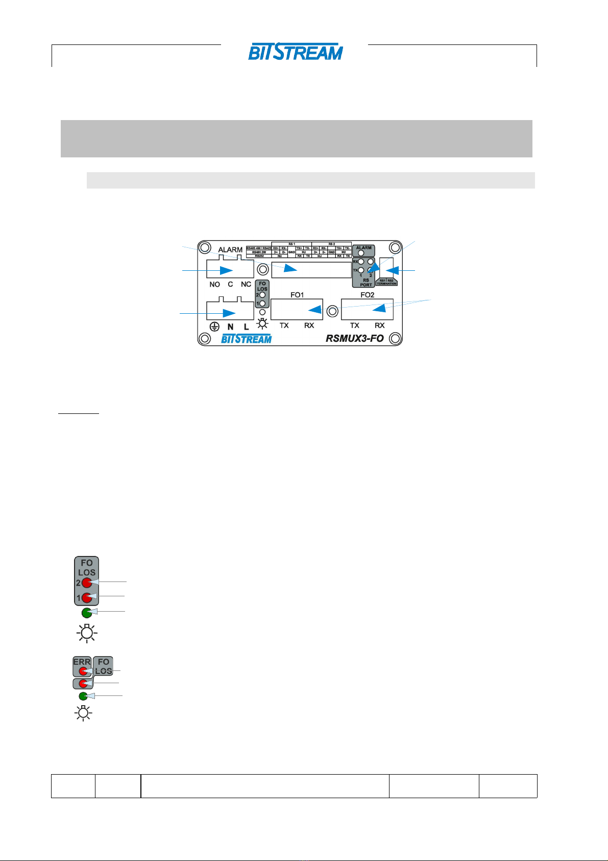
1 TOP VIEW OF THE DEVICE
Img.1. Top panel of the device
Marking:
1 - alarm screw connector
2 - Indicator LEDs
3 - fiber optic interface connectors
4 - termination
5 - do ble RS232/422/485 interface connector (MM version for 1x FO available in one RS1 interface
connector)
6 - power s pply connector 230 V AC
1.1 Description of signalling
Marking of do ble port indicator lights:
1 - FO LOS 1 - LED indicating no signal on optical interface 1
2 - FO LOS 1 - LED indicating the lack of signal on the optical interface no. 1
3 - power stat s signalling to the device.
Marking of signaling LEDs with a single port:
1 - ERR - LED indicating transmission error when the device operates with one
optical port
2 - FO LOS - LED indicating no signal on the optical interface
3 - power stat s signalling to the device.
Img.2. LED diode system with double or single optical port in R MUX3-FO converter
RSMUX3-FO SHORT USER MANUAL 1/5REV. 1.04 2019.05.17
3
2
14
6
5
1
2
3
1
2
3
Quick start manual, a detailed manual is on the enclosed CD or can be downloaded from
company's website www.bitstream.com.pl/en/
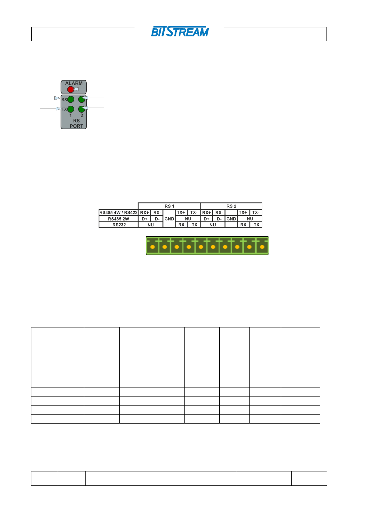
Marking of signaling diodes:
1 - Tx1 - LED indicates transmitting signal on port 1,
2 - Rx1 - LED indicates reception of signal on port 1,
3 - Tx2 - LED indicates transmitting signal on port 2,
4 - Rx2 - the diode indicates reception of the signal on port 2,
5 - ALARM - LED indicates loss of optical signal
Img.3. ignalling of the serial interface of the R MUX3-FO converter
1.2 Description of the RS232/422/485 comm nication interface
The do ble interface on the front of the device enables RS232, RS422 or RS485 transmission.
(In MM version for 1x FO only one interface connector is available – RS1)
Img.4. Appearance of the communication interface for serial R transmission.
1.3 Description of optical interfaces
Depending on the version, ST/PC, SC/PC or SFP slots are available. The device with the
symbol "P" is eq ipped with an additional optical port to provide protection or work in the ring.
Device version Connector
type for FO
Fibre optic type Transmitter
power
Receiver
sensitivity
Range Wavelength
RSMUX3-FO-MM** ST 50,62.5/125 m -18.8dBm* -25.4dBm 1.5km 850nm
RSMUX3-FO-S SC 9/125 m; 50, 62.5/125 m -20dBm* -32dBm 15km*/5km 1310nm
RSMUX3-FO-M SC 9/125 m -5dBm* -35dBm 60km* 1310nm
RSMUX3-FO-L SC 9/125 m, +5dBm* -35dBm 120km* 1550nm
RSMUX3-FO-WS SC 9/125 m, 62.5/125 m -14dBm* -32dBm 20km* 1310/1550nm
RSMUX3-FO-WM SC 9/125 m -8dBm* -34dBm 40km* 1310/1550nm
RSMUX3-FO-WL SC 9/125 m +0dBm* -36dBm 60km* 1310/1550nm
RSMUX3-FO-WLL SC 9/125 m -5dBm* -33dBm 100km* 1510/1570nm
RSMUX3-FO-SFP LC/SC 9/125 m, 62.5/125 m - - - -
* - The parameters refer to the 9/125 m fibre.
** - For 'MM' version there is no ring, it works as two independent converters, with one FO1 port only one RS1 or respectively
FO2/RS2, alarm only for power fail re, additional advantage is s pport for IEC103 protocol from FO side.
RSMUX3-FO SHORT USER MANUAL 2/5REV. 1.04 2019.05.17
5
4
3
1
2

Quick start manual, a detailed manual is on the enclosed CD or can be downloaded from
company's website www.bitstream.com.pl/en/
2 POWER S PPLY
– Voltage range for version 120-260V DC and 100-240V AC
– C rrent cons mption 230V AC/ 200mA
– Voltage polarity – the polarization on power connector is very important
– Screw connection for power s pply - triple block terminal, screwed connector for 3 mm2 diameter
cable
3 FIRST START-P
The device is factory set to active RS485 (2W) interface (DIP-SWITCHA - OFF defa lt
config ration) for all serial ports.
4 DEVICE CONFIG RATION
The nit parameters are config red sing the three DIP switches on the rear of the nit. They are
sed to config re the RING, serial interface parameters and to switch the operating modes of the
device.
Img.5. Rear panel view
Config ration of the RING and SLOW MODE
RING CONFIG
1 2 3 4
OFF ON OFF NU MAS. WITH
PROTECT.
ON OFF OFF NU SL.
- - - OFF NORMAL MODE
- - - ON SM SLOW MODE
OFF OFF ON NU 64 D.
WITHOUT
PROTECT.
ON OFF ON NU 16 D.
OFF ON ON NU 8 D.
ON ON ON NU 4 D.
RSMUX3-FO SHORT USER MANUAL 3/5REV. 1.04 2019.05.17

Quick start manual, a detailed manual is on the enclosed CD or can be downloaded from
company's website www.bitstream.com.pl/en/
Serial interface config ration
CONFIG
Port config ration
Electrical Interface
RS1 RS2
1 2 3 4
OFF OFF OFF OFF RS-485(2W)
OFF ON OFF ON RS-485(4W)
ON OFF ON OFF RS-422
ON ON ON ON RS-232
Compatible with BS-MC-50
SW1 FUNCTION
Switch 1 ON FO2 OFF
OFF FO2 ON
Switch 2 ON BS-MC-50 MODE
OFF NORMAL MODE
Switch 3 NU NU
Switch 4 NU NU
Switch 1 - disabling FO2 port
Switch 2 - f nction of cooperation with BS-MC-50 device
Switch 3 - not sed
Switch 4 - not sed
5 CONFORMITY TO STANDARDS AND RECOMMNEDATIONS
BITSTREAM devices were designed p rs ant to obligatory standards and recommendations in
respect of the range of data transmission, electromagnetic compatibility and service safety.
5.1 Electromagnetic compatibility
The device was designed p rs ant to the standard EN 55011, EN 61000. BITSTREAM devices
are designated to f nctioning in closed premises.
Notice: This device is a class A device. In the residential environment may cause radio frequency
interference. In such cases, you can require the user to take appropriate measures.
5.2 Safety
In respect to safety of service, BITSTREAM devices were designed and tested for operation
safety along with the EN 60950 standard.
RSMUX3-FO SHORT USER MANUAL 4/5REV. 1.04 2019.05.17

Quick start manual, a detailed manual is on the enclosed CD or can be downloaded from
company's website www.bitstream.com.pl/en/
Config ration and installation of the device sho ld be carried o t by personnel with the
necessary a thorizations and q alifications in the scope of operation, maintenance, assembly of
devices and installations of power networks.
The device sho ld be installed in cabinets or facilities where access is limited only for q alified
personnel. The following notes sho ld be observed d ring installation.
The device should be installed in cabinets or facilities where access is limited only for
qualified personnel. The following notes should be observed during installation.
The power cable should always be connected to a power source with the possibility of
earth connection to the grounding screw terminal.
It is not permissible to use earthing and zeroing simultaneously via the mains supply
cable.
Dual fuse - pole/zero. Each power cord (L, N) is protected by a separate fuse located
inside the unit. If only one of the fuses is damaged, other components may remain live.
Some parts of the power supply unit located on the PCB are located on the mains
potential.
To avoid contact with live components, always disconnect the power supply before
removing the housing cover.
The device does not have a built-in disconnecting system. Such a system should be
located outside the device.
In the case when the device is powered from 230 V mains, the plug on the power cord serves
as a disconnecting element and the plug socket should be located near the device and be
easily accessible for service.
The manufacturer is not responsible for any events arising from the use and installation of
the device not in accordance with the operating instructions.
The user's manual is an integral part of the device and is handed over to the users with it.
6 PACKING COMPLETION OF THE PROD CT
1 RSMUX3-FO 1 pc
2 User man al on CD 1 pc
3 Short ser man al 1 pc
4 Declaration of conformity 1 pc
5 Connector for RS and Power and alarms interface 3 pc
RSMUX3-FO SHORT USER MANUAL 5/5REV. 1.04 2019.05.17
This manual suits for next models
9
Table of contents
Other Bitstream Media Converter manuals


Popular Media Converter manuals by other brands

Hama
Hama 00121775 operating instructions

Siko
Siko WH58MR Original Installation Instructions

EtherWAN
EtherWAN EL100 installation guide

TR-Electronic
TR-Electronic CEH582M-8192/32768 EPN DMS 12H7 KRF Assembly instructions

ADF Web
ADF Web HD67517-B2 user manual

Balluff
Balluff BAE SA-FF-055-RS quick start guide


