Motrona DZ 270 User manual

control – motion – interface
motrona GmbH
Zwischen den Wegen 32
78239 Rielasingen - Germany
Tel. +49 (0)7731-9332-0
Fax +49 (0)7731-9332-30
www.motrona.com
DZ27001a_e.doc / Jan-13 Page 1 / 36
DZ 270, 271, 276, 277, 279
Universal Monitors for Speed,
Standstill, Direction of Rotation
DZ270: Monitor with 3 programmable output relays and 1 analogue output
DZ271: Monitor with 3 programmable transistor outputs and 1 analogue output
DZ276: Monitor with 1 analogue output only
DZ277: Monitor with 3 programmable output relays only
DZ279: Monitor with 3 programmable transistor outputs only
Compact and most versatile monitor series for control of overspeed, underspeed,
standstill and direction of rotation
Logical monitoring of remote motion enable signals
Input for connection to sin/cos encoders with 1 Vss format
Extremely wide frequency range up to 500 kHz
Easy setup by means of four keys and LCD menu
All models include serial RS232 interface
Operating Instructions

DZ27001a_e.doc / Jan-13 Page 2 / 36
Safety Instructions
This manual is an essential part of the unit and contains important hints about
function, correct handling and commissioning. Non-observance can result in
damage to the unit or the machine or even in injury to persons using the
equipment!
The unit must only be installed, connected and activated by a qualified electrician
It is a must to observe all general and also all country-specific and application-
specific safety standards
When this unit is used with applications where failure or maloperation could cause
damage to a machine or hazard to the operating staff, it is indispensable to meet
effective precautions in order to avoid such consequences
Regarding installation, wiring, environmental conditions, screening of cables and
earthing, you must follow the general standards of industrial automation industry
- Errors and omissions excepted –
General instructions for cabling, screening and grounding can be found in the
SUPPORT section of our website http://www.motrona.com
Version:
Description:
DZ27
00
1
a_sn_12/12
First edition

DZ27001a_e.doc / Jan-13 Page 3 / 36
Table of Contents
1. Introduction ................................................................................................. 4
2. Available Models......................................................................................... 4
3. Electrical Connections ................................................................................. 5
3.1. Power Supply.......................................................................................................10
3.2. Auxiliary Output for Encoder Supply ...................................................................10
3.3. Inputs for SinCos Encoders and Sensors.............................................................10
3.4. Control Inputs ......................................................................................................10
3.5. Serial Interface....................................................................................................11
3.6. Relay Outputs K1 – K3 (DZ270 and DZ 277 only)................................................11
3.7. Tansistor Outputs K1 – K3 (DZ271 and DZ 279 only)..........................................11
3.8. Scalable Analogue Output (DZ270, DZ271 and DZ 276 only) .............................11
4. LCD Display and Keys ................................................................................ 12
5. Keypad Operation...................................................................................... 13
5.1. Normal Operation................................................................................................13
5.2. Keypad Interlock..................................................................................................13
5.3. General Setup Procedure ....................................................................................14
5.4. Changing Parameters on the Setting Level.........................................................14
5.5. Return from the Menu, Time-Out Function .........................................................15
5.6. Reset all Parameters to Factory Default Values .................................................15
6. Menu Structure and Parameter Description............................................... 16
6.1. Survey of Menus .................................................................................................16
6.2. Parameter Descriptions.......................................................................................17
7. Example for Commissioning....................................................................... 29
8. Appendix ................................................................................................... 31
8.1. Hints for Use of the Linearization Function.........................................................31
8.2. Data Readout via Serial Interface.......................................................................32
8.3. “Relay Action”, override relay states by programmed states.............................33
8.4. Monitoring of remote motion enable signals......................................................34
9. Specifications and Dimensions.................................................................. 35

DZ27001a_e.doc / Jan-13 Page 4 / 36
1. Introduction
This new series of monitors has been designed as control modules for mounting inside of
electric control cabinets. The units are suitable for speed monitoring of machines, signaling
overspeed, underspeed, zero motion and the direction of rotation. Units providing an analogue
output can moreover be used for closed-loop control or feedback purpose within a control
system.
Very special advantages of these new monitors are the wide frequency range, the extremely
fast response and the remarkable versatility with regard to possible programmable monitoring
functions.
2. Available Models
There are five models available, all with fully similar basic functions, but with different options
concerning the outputs.
DZ = Function: Speed Monitor
DZ 270
27 = Housing with dimensions 72 x 91 mm
(2.835 x 3.583 ‘’), with LCD and keypad
0 = Analogue output + 3 relay outputs
1 = Anlaouge output + 3 transistor outputs
6 = Analogue output only
7 = Relay outputs only
9 = Transistor outputs only
DZ27001a_e.doc / Jan-13 Page 5 / 36
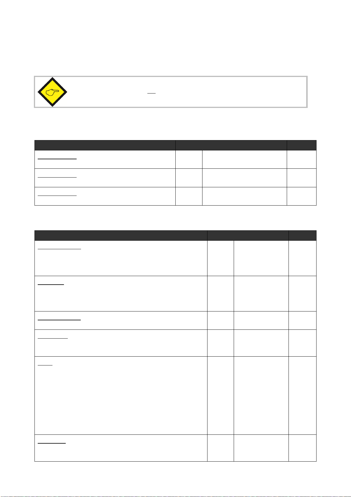
3. Electrical Connections
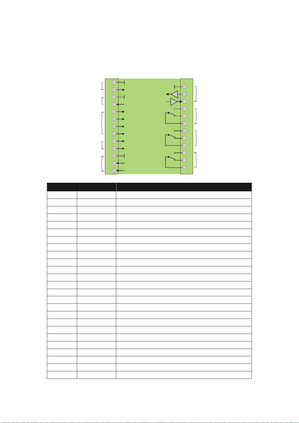
DZ270
1
2
3
4
5
6
7
8
9
1
0
1
1
1
2
1
3
1
4
1
5
1
6
1
7
1
8
1
9
2
0
2
1
2
2
2
3
2
4
2
5
GND (-)
GND
GND
GND
RxD
TxD
K1
K2
K3
+Power input
+5,2V
SIN+
SIN-
COS+
COS-
0 - 10 V
0/4 - 20 mA
Control 1
Control 2
Aux. Output
+5,2V
Input for
SIN/COS
encoders
Power supply
17 - 30 VDC
Control
inputs
Analogue
output
Serial RS232-
interface
NO
NC
C
NO
NC
C
NO
NC
C
Relay K1
Relay K2
Relay K3
Terminal
Text
Function
01 GND GND, common minus potential
02 Vin Power input, +17 – 30 VDC
03 GND GND, common minus potential
04 +5,2V Aux. output 5,2V / 200 mA
05 SIN+ SIN+ input for encoder
06 SIN- SIN- input for encoder
07 COS+ COS+ input for encoder
08 COS- COS- input for encoder
09 Control 2 Control input with programmable function
10 Control 1 Control input with programmable function
11 GND GND, common minus potential
12 +10V Out Analogue output 0 – 10 V
13 20mA out Analogue output 0 – 20 mA
14 GND GND, common minus potential
15 RXD Serial RS232 interface, data input
16 TXD Serial RS232 interface, data output
17 K1NO Relay 1, normally open contact
18 K1NC Relay 1, normally closed contact
19 K1C Relay 1, common contact
20 K2NO Relay 2, normally open contact
21 K2NC Relay 2, normally closed contact
22 K2C Relay 2, common contact
23 K3NO Relay 3, normally open contact
24 K3NC Relay 3, normally closed contact
25 K3C Relay 3, common contact
DZ27001a_e.doc / Jan-13 Page 6 / 36
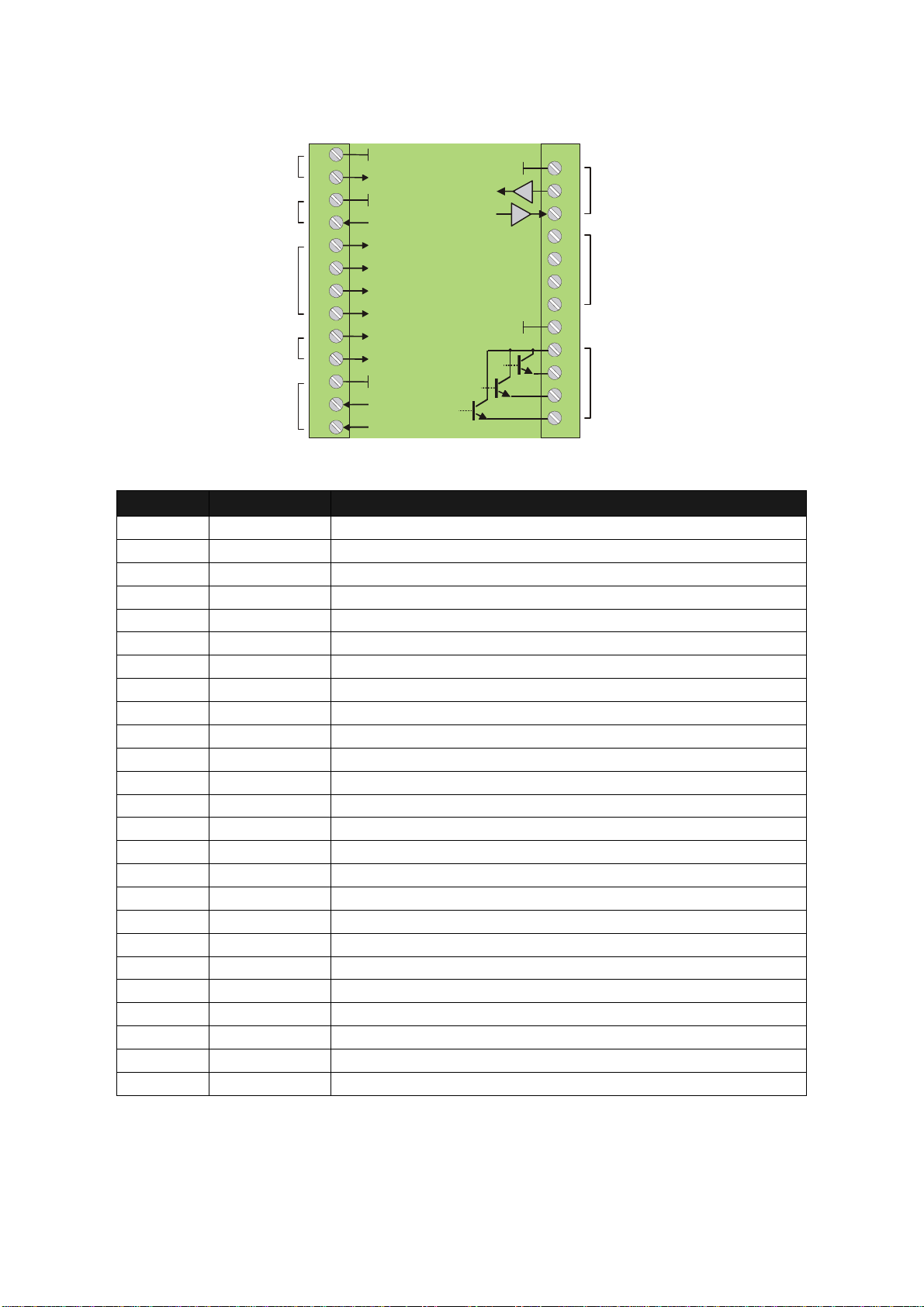
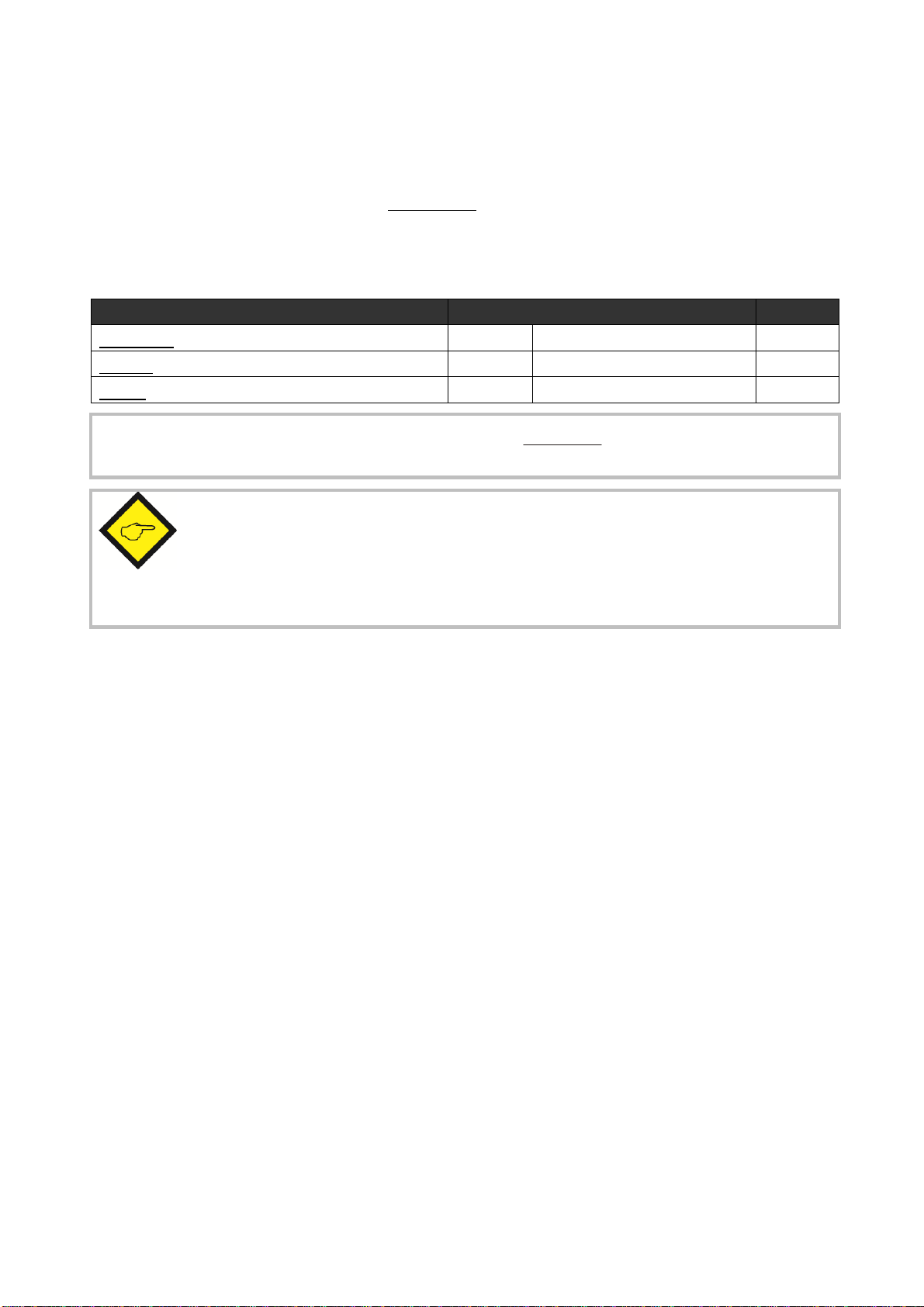
DZ271
1
2
3
4
5
6
7
8
9
1
0
1
1
1
2
1
3
1
4
1
5
1
6
1
7
1
8
1
9
2
0
2
1
2
2
2
3
2
4
2
5
GND (-)
GND
GND
GND
RxD
TxD
+Power supply
+5,2V
0 - 10 V
0/4 - 20 mA
Control 1
Control 2
Aux. output
+5,2V
Power supply
17 - 30 VDC
Control
inputs
Analogue
output
Serial RS232-
interface
Com + (5-30 V/DC)
GND
NC
K1 out
K2 out
K3 out
SIN+
SIN-
COS+
COS-
Input for
SIN/COS
encoders
Terminal
Text
Function
01 GND GND, common minus potential
02 Vin Power input, +17 – 30 VDC
03 GND GND, common minus potential
04 +5,2V Aux. output 5,2V / 200 mA
05 SIN+ SIN+ input for encoder
06 SIN- SIN- input for encoder
07 COS+ COS+ input for encoder
08 COS- COS- input for encoder
09 Control 2 Control input with programmable function
10 Control 1 Control input with programmable function
11 GND GND, common minus potential
12 +10V Out Analogue output 0 – 10 V
13 20mA out Analogue output 0 – 20 mA
14 GND GND, common minus potential
15 RXD Serial RS232 interface, data input
16 TXD Serial RS232 interface, data output
17 NC Not connected
18 NC Not connected
19 NC Not connected
20 NC Not connected
21 GND GND, common minus potential
22 Com + Common positive input for transistor outputs K1-K3
23 K1 out Output K1, transistor PNP 30 volts, 350 mA
24 K1 out Output K2, transistor PNP 30 volts, 350 mA
25 K1 out Output K3, transistor PNP 30 volts, 350 mA

DZ27001a_e.doc / Jan-13 Page 7 / 36
DZ276
1
2
3
4
5
6
7
8
9
1
0
1
1
1
2
1
3
1
4
1
5
1
6
1
7
1
8
1
9
2
0
2
1
2
2
2
3
2
4
2
5
GND (-)
GND
GND
GND
RxD
TxD
+Power supply
+5,2V
0 - 10 V
0/4 - 20 mA
Control 1
Control 2
Aux. Output
+5,2V
Power supply
17 - 30 VDC
Control
inputs
Analogue
output
Serial RS232-
interface
NC
Input for
SIN/COS
encoders
SIN+
SIN-
COS+
COS-
Terminal
Text
Function
01 GND GND, common minus potential
02 Vin Power input, +17 – 30 VDC
03 GND GND, common minus potential
04 +5,2V Aux. output 5,2V / 200 mA
05 SIN+ SIN+ input for encoder
06 SIN- SIN- input for encoder
07 COS+ COS+ input for encoder
08 COS- COS- input for encoder
09 Control 2 Control input with programmable function
10 Control 1 Control input with programmable function
11 GND GND, common minus potential
12 +10V Out Analogue output 0 – 10 V
13 20mA out Analogue output 0 – 20 mA
14 GND GND, common minus potential
15 RXD Serial RS232 interface, data input
16 TXD Serial RS232 interface, data output
17 NC Not connected
18 NC Not connected
19 NC Not connected
20 NC Not connected
21 NC Not connected
22 NC Not connected
23 NC Not connected
24 NC Not connected
25 NC Not connected
DZ27001a_e.doc / Jan-13 Page 8 / 36
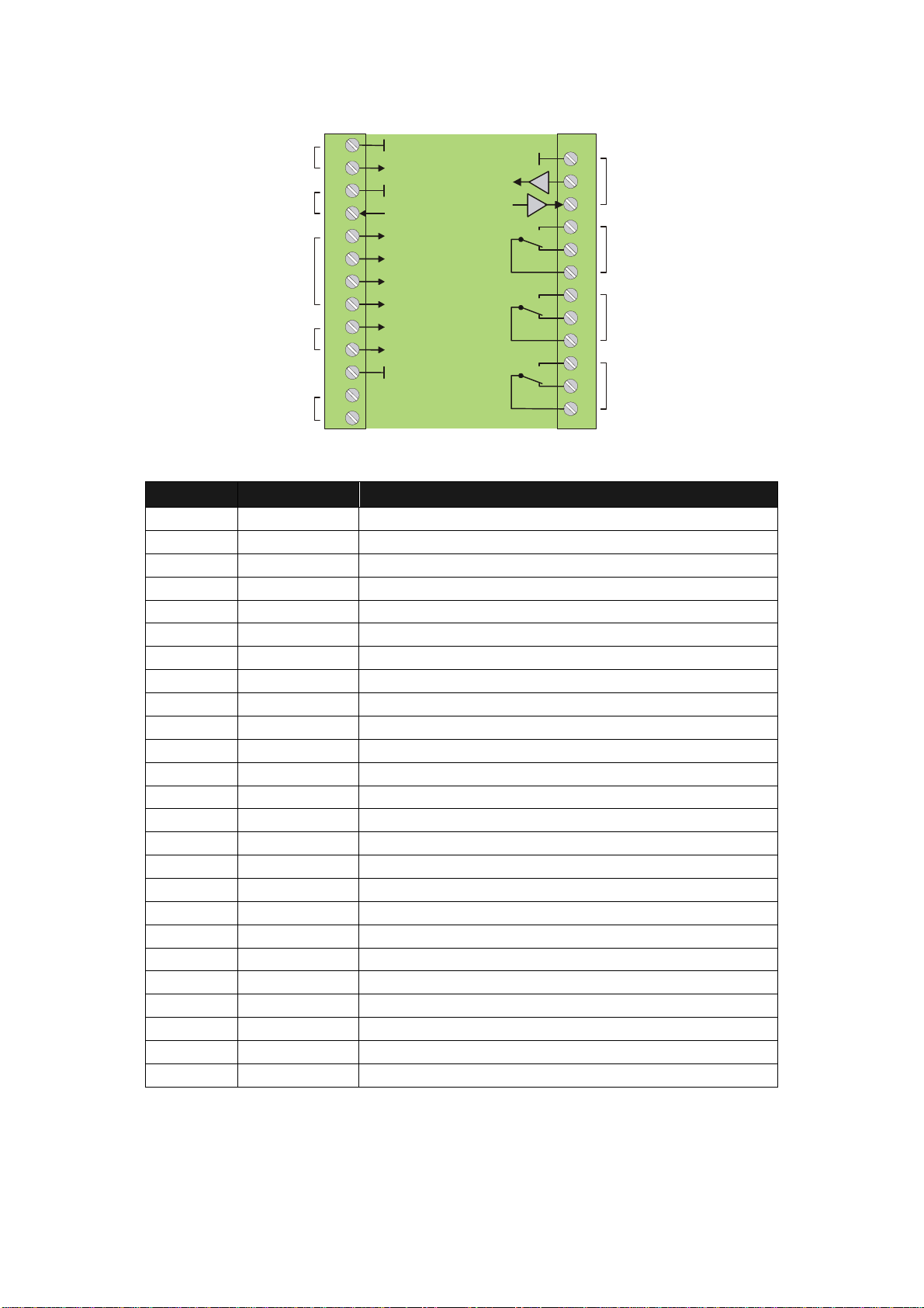
DZ277
1
2
3
4
5
6
7
8
9
1
0
1
1
1
2
1
3
1
4
1
5
1
6
1
7
1
8
1
9
2
0
2
1
2
2
2
3
2
4
2
5
GND (-)
GND
GND
GND
RxD
TxD
K1
K2
K3
+Power supply
+5,2V
Control 1
Control 2
Aux. output
+5,2V
Power supply
17 - 30 VDC
Control
inputs
NC
Serial RS232-
interface
NO
NC
C
NO
NC
C
NO
NC
C
Relay K1
Relay K2
Relay K3
SIN+
SIN-
COS+
COS-
Input for
SIN/COS
encoders
Terminal
Text
Functi
on
01 GND GND, common minus potential
02 Vin Power input, +17 – 30 VDC
03 GND GND, common minus potential
04 +5,2V Aux. output 5,2V / 200 mA
05 SIN+ SIN+ input for encoder
06 SIN- SIN- input for encoder
07 COS+ COS+ input for encoder
08 COS- COS- input for encoder
09 Control 2 Control input with programmable function
10 Control 1 Control input with programmable function
11 GND GND, common minus potential
12 NC Not connected
13 NC Not connected
14 GND GND, common minus potential
15 RXD Serial RS232 interface, data input
16 TXD Serial RS232 interface, data output
17 K1NO Relay 1, normally open contact
18 K1NC Relay 1, normally closed contact
19 K1C Relay 1, common contact
20 K2NO Relay 2, normally open contact
21 K2NC Relay 2, normally closed contact
22 K2C Relay 2, common contact
23 K3NO Relay 3, normally open contact
24 K3NC Relay 3, normally closed contact
25 K3C Relay 3, common contact

DZ27001a_e.doc / Jan-13 Page 9 / 36
DZ279
1
2
3
4
5
6
7
8
9
1
0
1
1
1
2
1
3
1
4
1
5
1
6
1
7
1
8
1
9
2
0
2
1
2
2
2
3
2
4
2
5
GND (-)
GND
GND
GND
RxD
TxD
+Power supply
+5,2V
Control 1
Control 2
Aux. output
+5,2V
Power supply
17 - 30 VDC
Control
inputs
NC
Serial Rs232-
interface
Com + (5-30 V/DC)
GND
NC
K1 out
K2 out
K3 out
Input for
SIN/COS
encoders
SIN+
SIN-
COS+
COS-
Terminal
Text
Function
01 GND GND, common minus potential
02 Vin Power input, +17 – 30 VDC
03 GND GND, common minus potential
04 +5,2V Aux. output 5,2V / 200 mA
05 SIN+ SIN+ input for encoder
06 SIN- SIN- input for encoder
07 COS+ COS+ input for encoder
08 COS- COS- input for encoder
09 Control 2 Control input with programmable function
10 Control 1 Control input with programmable function
11 GND GND, common minus potential
12 NC Not connected
13 NC Not connected
14 GND GND, common minus potential
15 RXD Serial RS232 interface, data input
16 TXD Serial RS232 interface, data output
17 NC Not connected
18 NC Not connected
19 NC Not connected
20 NC Not connected
21 GND GND, common minus potential
22 Com + Common positive input for transistor outputs K1-K3
23 K1 out Output K1, transistor PNP 30 volts, 350 mA
24 K1 out Output K2, transistor PNP 30 volts, 350 mA
25 K1 out Output K3, transistor PNP 30 volts, 350 mA

DZ27001a_e.doc / Jan-13 Page 10 / 36
3.1. Power Supply
The units require a DC supply from 17 to 30 volts which must be applied to terminals 1 and 2.
Depending on the input voltage level and internal states, the power consumption may vary and
lies in a range of about 70 mA with a 24 volts input (plus encoder currents taken from the
auxiliary voltage output).
3.2. Auxiliary Output for Encoder Supply
Terminals 4 and 3 provide a +5.2 VDC / 200 mA auxiliary output for supply of encoders and
sensors.
3.3. Inputs for SinCos Encoders and Sensors
The encoder shall be connected at the screw-type terminal 5-8 of the device. Only encoders
with differential sine-cosine signals of 1 Vpp can be used (0.8 Vpp - 1.2 Vpp). At any time the
signals sin+/sin- and cos+/cos- must be available.
Pins 3 (GND) and 4 (+5,2 V) of the screw-type terminal provide an auxiliary power output for the
encoder supply.
3.4. Control Inputs
Two programmable control inputs allow the assignment of functions like remote start-up-delay,
reset of relay lock, hardware interlock of the keypad and similar.
Both inputs provide PNP characteristics and require HTL level. Also it is possible to set the
control function to "active LOW" or "active HIGH".
For evaluation of dynamic events the desired "active edge" can be set (rising or falling edge)

DZ27001a_e.doc / Jan-13 Page 11 / 36
3.5. Serial Interface
The serial RS232 interface in general may be used
for easy setup and commissioning of the units (with use of the OS32 operator software)
to change settings and parameters by PC or PLC during the operation
to read out internal states and actual measuring values by PC or PLC
The subsequent drawing shows how to link the monitor with a PC, using the standard
9-pin Sub-D-9 connector
2
3
5
RxD
RxD
TxD
TxD
GND
Screen
PC
DZ 270
DZ 271
DZ 276
DZ 277
DZ 279
15
(Sub-D-9)
16
14
3.6. Relay Outputs K1 – K3 (DZ270 and DZ 277 only)
The units provide three programmable relay outputs (all dry changeover), providing a switching
capability of 30 volts / 2 amps DC or 125 volts / 0.6 amps AC or 230 volts / 0.3 amps AC. Both,
switching characteristics and monitoring function may be programmed for each of the relays
individually.
3.7. Tansistor Outputs K1 – K3 (DZ271 and DZ 279 only)
The units provide three outputs with programmable switching characteristics.
K1 – K3 are fast-switching and short-circuit-proof transistor outputs with a switching capability
of 5 – 30 volts / 350 mA each. The switching voltage of the outputs must be applied remotely
to the Com+ input (terminal 22). Both, switching characteristics and monitoring function may be
programmed for each of the outputs individually.
3.8. Scalable Analogue Output (DZ270, DZ271 and DZ 276 only)
The units provide a voltage output with a +/-10 volts range (max. load 2 mA) and a current
output with ranges 0 – 20 mA respectively 4 – 20 mA (load 0 – 270 Ω). Beginning and end of
the desired conversion range can be set by the operator menu. The common potential of both
outputs refers to GND.
The total resolution is 14 bits. A settling time of approx. 200µs. is required. The overall
response time of the analogue outputs primarily depends on the selected Sampling Time
setting. After volatile jumps of the input signal, the analogue outputs may need up to two
Sampling Time cycles (plus 200 µsec.) to stabilize.

DZ27001a_e.doc / Jan-13 Page 12 / 36
4. LCD Display and Keys
The units provide a back-lit LCD displays with 2 lines at 16 characters each, and four keys for
setup and command control.
During the setup procedure the LCD display indicates the menu with all parameter texts and the
set values of the parameters.
During normal operation, the LCD display indicates the following information:
Actual speed value
Input frequency, scaled in user units
+156.5 Hz
I: LH O: COO +47 %
Analogue output (not with DZ267, DZ269)
Actual output level in % of full scale
O: Outputs (not with DZ266)
Actual switching states of relays/transistor outputs
(Rel1, Rel2, Rel3)/(out1, out2, out3)
C = Closed, O = Open
I: Inputs
aktueller logical state of inputs
(Control1, Control2)
L = Low, H = High
The "Display Menu" allows free scaling of the speed measuring values and the speed-related
parameters to any kind of engineering units.
DZ27001a_e.doc / Jan-13 Page 13 / 36
5. Keypad Operation
A summary of all parameters and a detailed description of parameter functions is available
under section 6.
For all operation, the units provide four front keys which subsequently will be named as shown
below:
PROG
UP
DOWN
ENTER
The key functions depend on the actual operating state of the units. Basically we have to
distinguish between Normal Operation and Setup Operation
5.1. Normal Operation
While in normal operation state, the units monitor the speed according to the selected
operational parameters and settings. Each of the front keys provides the command functions as
attached to it upon setup in the "Command Menu"
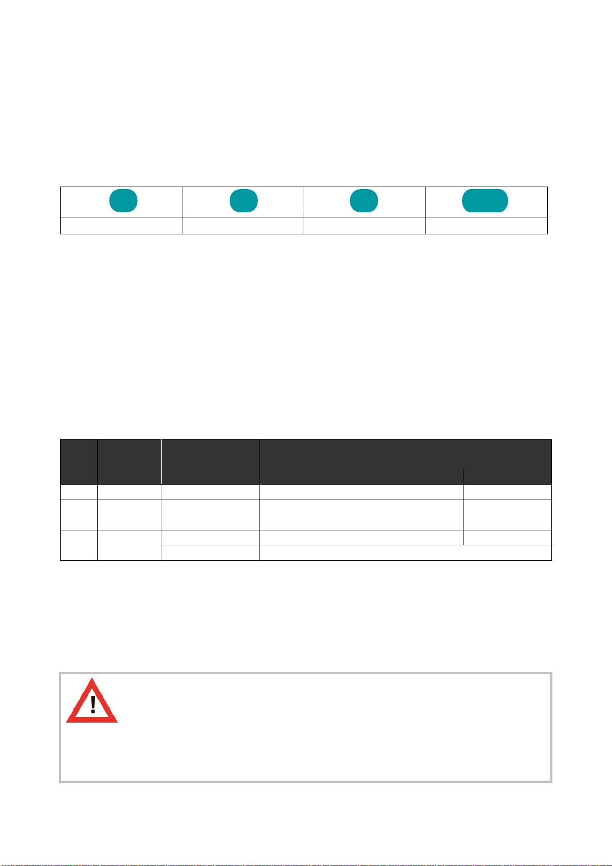
5.2. Keypad Interlock
There is a 3-stage conception to protect the keys against unauthorized changes of the
configuration respectively against activation of commands.
Stage Protected
Range
Protection
by
Key Operations
Change of Parameters Commands
1--- --- permitted permitted
2Menu Password upon
activation of menu
Protection of selectable parts of the menu
via password
permitted
3Keyboard Hardware-Latch 1 interlocked permitted
Hardware Latch 2 All functions interlocked
The "Key Pad" menu allows to define an individual password for each group of parameters. This
function can be used to provide individual access rights to different operators. Upon access to
an interlocked section the unit asks for the corresponding password. If the correct password is
not entered in time, the unit denies access and automatically returns to normal operation.
The hardware latch function can be activated and deactivated by one of the Control Inputs, or
by means of serial access to the corresponding locking register.
Using the Hardware Latch function may accidentally cause a total locking of all
functions, when the Control Inputs characteristics have been set inauspiciously.
In this exceptional case you can release the key functions again by either
a) applying the correct logical state (High or Low) to the inputs
b) or resetting the parameters to their default values (see section 5.6.)
c) or change the parameters being responsible for the locking by PC
P

DZ27001a_e.doc / Jan-13 Page 14 / 36
5.3. General Setup Procedure
To change over from normal operation to the setup state, please keep down the PROG key for
at least 2 seconds. After this the menu appears and you can select one of the menu groups.
Inside each group you can select the desired parameter and edit the setting according to need.
After this you are free to edit more parameters, or to return to normal operation.
The function of the different keys during setup is shown in the table below.
Key
Menu Level
Parameter Level
Setting Level
PROG
Save settings and return
to normal operation
Return to Menu Level Check entry, store result,
then go back to Parameter
Level
UP
Switch over to next
menu
Select next parameter Increment the highlighted
digit or scroll the setting
upwards
DOWN
Go back to previous
menu
Select previous parameter Decrement the highlighted
digit or scroll the setting
downwards
ENTER
Switch over to the
Parameter Level of the
current menu
Switch over to
Setting Level
Shifts the highlighted digit
one position to the left, or
from utmost left to utmost
right
5.4. Changing Parameters on the Setting Level
With signed parameters, the front digit can only be changed between „+“ (positive) and „-„
(negative). The subsequent example explains how to change a parameter from originally 1024
to a new value of 250 000.
The example assumes that you are already on the Setting Level, i.e. you have already selected
the corresponding parameter and read its actual value on the display. Highlighted (blinking)
digits are marked by background color and indicate the cursor position.

DZ27001a_e.doc / Jan-13 Page 15 / 36
No.
Display
Key action
Comment
00
00102
4
The actual value 1024 is displayed, with
the last digit blinking
01
4 x
Change last digit to 0
02
00102
0
Shift cursor to left
03
0010
2
0
2 x
Change highlighted digit to 0
04
0010
0
0
2 x
Shift curser to
left by 2 positions
05
00
1
000
Change highlighted digit to 0
06
00
0
000
Shift cursor to left
07
0
0
0000
5 x
Change highlighted digit to 5
08
0
5
0000
Shift cursor to left
09
0
50000
2 x
Change highlighted digit to 2
10
2
50000
Save new setting and return to
Parameter Level
5.5. Return from the Menu, Time-Out Function
At any time the PROG key changes the Menu by one level backwards or fully back to the normal
operation mode. The menu also switches automatically one level backwards, every time when
for 10 seconds no key has been touched (Time-Out-Function).
5.6. Reset all Parameters to Factory Default Values
If applicable, the whole set of parameters can be reset to factory default values (e.g. because a
code for the keypad interlocking has been forgotten, or because the unit does no more work
correctly for reasons of bad settings). All default values are indicated in the following
parameter tables.
To execute this Reset procedure, you have to take the following steps:
Power the unit down
Press
and
simultaneously
Switch power on with both keys held down
Where you decide to execute this action, please be aware that all parameter
settings will be lost, and you will have to repeat the whole setup procedure

DZ27001a_e.doc / Jan-13 Page 16 / 36
6. Menu Structure and Parameter Description
All parameters are combined to groups, arranged in several menus. You must only set those
parameters which are really relevant for your individual application.
6.1. Survey of Menus
This section provides an overview of the menus and their assignments to the different functions
of the units. The menu names are printed bold, and associated parameters are arrayed directly
under the menu names.
Menu texts are in English, according to the presentation on the LCD display
Preselect.-Menu*Encoder-Menu Ser.Readout Menu Special-Menu
Preselection 1 Encoder Proper Multiplier Linear Mode**
Preselection 2 Direction Divider Freq. Control
Preselection 3 Sampling Time Offset Input Filter
Wait Time
Filter
Set Value
Key-Pad-Menu Command-Menu
***
Analogue-Menu** Serial-Menu
Protect Menu M01 Key Up Func. Analogue Format Unit Number
Protect Menu M02 Key Down Func. Analogue Start Serial Baud Rate
Protect Menu M03 Key Enter Func. Analogue End Serial Format
… Input 1 Config. Analogue Swing Serial Protocol
Protect Menu M09 Input 1 Func. Analogue Offset Serial Timer
Protect Menu M10 Input 2 Config. Register Code
Protect Menu M11 Input 2 Func.
Switching-Menu*Linear.-Menu** Display-Menu
Pulse Time 1 P1(x) Up-Date-Time
Pulse Time 2 P1(y) Display Mode
Pulse Time 3 P2(x) Encoder Factor
Hysteresis 1 P2(y) Multiplier
Hysteresis 2 ..
Hysteresis 3 P14(x)
Preselect Mode 1 P14(y)
Preselect Mode 2 P15(x)
Preselect Mode 3 P15(y)
Output Polarity
Start up Mode
Start up Relay (*) not relevant with DZ 276
(**) not relevant with DZ 277, DZ 279
(***) partially inactive with DZ 276
Lock Relay
Standstill Time
DZ27001a_e.doc / Jan-13 Page 17 / 36
6.2. Parameter Descriptions
6.2.1. Preselections
Preselection parameters are not relevant for model DZ276
These parameters assign the desired switching points to the relays/outputs. The preselections
use the same engineering units as the display of the actual speed (see Display-Menu).
Preselection Menu
Code
Setting Range
Default
Preselection1
Switching point of relay 1/ out 1 (engineering units)
„00“ -1 000 000.0 ... +1 000 000.0 100.0
Preselection2
Switching point of relay 2/ out 2 (engineering units)
„01“ -1 000 000.0 ... +1 000 000.0 200.0
Preselection3
Switching point of relay 3/ out 3 (engineering units)
„02“ -1 000 000.0 ... +1 000 000.0 300.0
6.2.2. Definitions for the Encoder or Speed Sensor
Encoder
-
Menu
Code
Setting Range
Default
Encoder Proper
Encoder properties
„A0“ 0..1 0
0
1
SIN+/SIN-/COS+/COS-
SIN+/SIN-
Direction
Definition of the direction of rotation with quadrature encoders
„A1“ 0, 1 0
0 forward when A leads B
1 forward when B leads A
Sampling Time
Internal time base for sampling of the input frequency (sec.)
„A2“ 0.001..9.999 0.001
Wait Time
Time to wait before unit detects zero speed (sec.)
Impulse distances greater than this time will be takes as zero
„A3“ 0.01..9.99 1.00
Filter
Digital filter for smoothing of unstable frequencies
„A4“ 0..7 0
0 Filter off
(very fast response to frequency changes)
1Τ(63%) = 1,9 msec. with Sampling Time = 1msec.
2Τ(63%) = 3,8 msec. with Sampling Time = 1msec.
etc.
7Τ(63%) = 122 msec. with Sampling Time = 1msec.
(very slow response to frequency changes)
Set Value
Fixed frequency set value for encoder simulation (Hz)
(see also "Command"-Menu)
„A5“ -1 000 000.0 ...
+1 000 000.0
0
DZ27001a_e.doc / Jan-13 Page 18 / 36
6.2.3. Serial Readout Menu
An actual value proportional to the input frequency can be read out via serial link, accessing the
serial readout register (code :8 ) As a Basic Value this register uses the scaling set for the
analogue output, i.e. a range from 0 to 10 000 units corresponding to 0 - 100,00% of the full
scale output (see "Analogue Menu"). This readout can still be rescaled to user-friendly
engineering units, using the following parameters:
Serial Readout Menu
Code
Setting Range
Default
Multiplier
„A8“ -99999…99999 10000
Divider
„A9“ 0…99999 0
Offset
(absolute term) „B0“ -99999999…99999999 0
Readout (:8) = Basic Value x
Multiplier
Divider
+ Offset
The definition of the "Basic Value" occurs in the "Analogue Menu" and is also
available for the DZ277 units without analogue output
the ratio Multiplier / Divider must never be greater than 15 000
Setting "Divider" to zero will skip the rescaling procedure, resulting in a shorter
response time with all functions of the unit
More details about serial communication can be found in the appendix.

DZ27001a_e.doc / Jan-13 Page 19 / 36
6.2.4. Special-Menu
Special
-
Menu
Code
Setting Range
Default
Linear Mode
Programmable linearization for Basic Value and Analogue Output
„B3“ 0..2 0
0 Linearization off
1 Linearization range 0 – +10V
2 Linearization range -10V … +10V
Freq. Control
Defines behavior and response of the unit to sudden interruptions
of the input frequency.
This parameter must only be changed in very special cases and
under special instruction of an motrona engineer.
Otherwise please use always the default setting "2"!
„B4“ 0..2 2
Input Filter
Digital filter for limitation of the input frequency
„B5“ 0..3 0
0 Filter off, the full range of frequency will be evaluated
1 Filter to cut frequencies higher than 500 kHz
2 Filter to cut frequencies higher than 100 kHz
3 Filter to cut frequencies higher than 10 kHz
Using the Input Filter will cause wrong frequency measurement when you use the unit
with frequencies higher than indicated above.
6.2.5. Key-Pad-Menu
Key
-
Pad
-
Menu
(Passwords for menu groups)
Code
Setting Range
Default
Protect Menu 01 (
Preselect.-Menu
)
„C0“ 0..999999 0
Protect Menu 02 (
Encoder-Menu
)
„C1“
Protect Menu 03 (
Ser.Readout.-Menu
)
„C2“
0 = no interlock
Protect Menu 04 (
Special-Menu
)
a)
„C3“ 6079
Protect Menu 05 (
Key-Pad-Menu
)
„C4“
1
–
999 999 =
Protect Menu 06 (
Command-Menu
)
„C5“
Password for the
Protect Menu 07 (
Analogue-Menu
)
„C6“
corresponding
Protect Menu 08 (
Serial-Menu
)
„C7“
group
Protect Menu 09 (
Switching-Menu
)
„C8“
Protect Menu 10 (
Linear-Menu
)
„C9“
Protect Menu 11 (
Display-Menu
)
„D0“
a) This menu is protected by the password 6079 due to factory setting. After entry of the
password please press the Enter button at least 2 seconds.

DZ27001a_e.doc / Jan-13 Page 20 / 36
6.2.6. Command-Menu
Command
-
Menu
(assignment of functions)
Code
Setting Range
Default
Key Up Func
.
Supplementary command function of the UP key
„D7“ 0..9 0
0 no function
1 Activation of a serial data transmission
2 Force programmed relay/output states / freeze (a)(c)
3 Frequency simulation according to parameter "Set Value"
4 Freeze actual input frequency
5 Remote start-up-delay function (a)
6 Release lock of relay 1 (a)
7 Release lock of relay 2 (a)
8 Release lock of relay 3 (a)
9 Release lock of all relays 1-3 (a)
Key Down Func
.
Supplementary command function of the DOWN key (see UP)
„D8“ 0..9 0
Key Enter Func
.
Supplementary command function of the ENTER key (see UP)
„D9“ 0..9 0
Input 1 Config
.
Switching characteristics of input „Control1“
„E0“ 0..3 0
0 Static low
1 Static High
2 Dynamic, rising edge
3 Dynamic, falling edge
Input 1 Func.
Control function of input „Control1“
„E1“ 0..12 0
0 no function
1 Activation of a serial data transmission
2 Force programmed relay/output states / Freeze (a)(c)
3 Frequency simulation according to parameter "Set Value"
4 Freeze actual input frequency
5 Remote start-up-delay function (a)
6 Release lock of relay 1/transistor output 1 (a)
7 Release lock of relay 2/transistor output 2 (a)
8 Release lock of relay 3/transistor output 3 (a)
9 Release lock of all relays 1-3/output 1-3 (a)
10 Interlock for parameter access via keypad (b)
11 Total keypad interlock (b)
12 Command monitor for remote motion enable signal
Input 2 Config
.
(see Input 1 Config.) „E2“ 0..3 0
Input 2 Func
.
(see Input 1 Func.) „E3“ 0..12 0
(a) these parameters are not relevant for model DZ276.
(b) see section 5.2 (c) see section 8.3 (d) see section 8.4
This manual suits for next models
4
Table of contents
Other Motrona Monitor manuals


