Motrona DZ260 User manual

Operating Manual
DZ260, 261, 266, 267, 269
Monitor for speed, standstill and direction of rotation with incremental encoder signals
Product features:
Compact and most versatile monitor series for control of
overspeed, underspeed, standstill and direction of rotation
Logical monitoring of remote motion enable signals
Universal inputs for connection to incremental encoders (TTL, RS422 or HTL),
proximity switches, photocells remote TTL signals
Extremely wide frequency range, operating from 0.1 Hz up to 1 MHz
Easy setup by means of four keys and LCD menu
All models include serial RS232 interface
Available devices:
DZ260: Monitor with 3 programmable output relays and 1 analog output
DZ261: Monitor with 3 fast switching transistor outputs and 1 analog output
DZ266: Monitor with 1 analog output only
DZ267: Monitor with 3 programmable output relays only
DZ269: Monitor with 3 fast switching transistor outputs only
3046 Home Road. Powell, OH 43065 P: (740) 917-5781 F: (740) 917-5791 www.GenesisAutomationOnline.com [email protected]
www.GenesisAutomationOnline.com

Dz260_05a_oi_e.doc / Dez-16 Page 2 / 40
Version:
Description:
DZ26001b_af/kk/hk_07/07
First edition in English
DZ26002a_af/kk/hk_01/08
Commands “Force Relays” and “Freeze Relays” added
DZ26003a_af/hk_11/08
Command Monitor for remote enable signal
DZ26003b_pp_11/11
Chapter 6.2.2 “Encoder properties” replaced TTL by HTL
DZ26003c_pp_07/12
Hint: “Special Menu” is password protected (Chap. 6.2.5)
DZ26003d_pp_11/12
Changed “Setting Range” for parameter “Wait Time” (code A3)
DZ26004a_sn_12/12
Additional device DZ261 and DZ269
DZ26004b_hk/nw_04/13
Small corrections
DZ26004c_sn_06/14
Small corrections Analog-Menu
Dz26004d/ag_04/15
Small corrections Analog-Menu.
New chapter 1. “Safety Instructions and Responsibility”.
Dz260_04e_ag / Aug-15
- Analog output 4.13 –hint: only V or mA can be used (not both together)
- Analog menu 7.2.7 –some hints and a setup example supplemented
- Some smaller corrections and modulations
Dz260_05a_af / Okt-16
Parameter Analogue ABS added
Parameter Preselection Mode increased to 9
Legal notices:
All contents included in this manual are protected by the terms of use and copyrights of motrona GmbH. Any
reproduction, modification, usage or publication in other electronic and printed media as well as in the internet requires
prior written authorization by motrona GmbH.

Dz260_05a_oi_e.doc / Dez-16 Page 3 / 40
Table of Contents
1. Safety Instructions and Responsibility ......................................................... 5
1.1. General Safety Instructions...................................................................................5
1.2. Use according to the intended purpose ................................................................5
1.3. Installation.............................................................................................................6
1.4. Cleaning, Maintenance and Service Notes...........................................................6
2. Introduction ................................................................................................. 7
3. Available Models......................................................................................... 7
4. Electrical Connections ................................................................................. 8
4.1. DZ260 ....................................................................................................................8
4.2. DZ261 ....................................................................................................................9
4.3. DZ266 ..................................................................................................................10
4.4. DZ267 ..................................................................................................................11
4.5. DZ269 ..................................................................................................................12
4.6. Power Supply.......................................................................................................13
4.7. Auxiliary Output for Encoder Supply ...................................................................13
4.8. Impulse Inputs for Encoders and Sensors ...........................................................13
4.9. Control Inputs ......................................................................................................13
4.10. Serial Interface....................................................................................................14
4.11. Relay Outputs K1 –K3 (DZ260 and DZ267 only).................................................14
4.12. Transistor Outputs K1 –K3 (DZ261 and DZ269 only)..........................................14
4.13. Scalable Analog Output (DZ260, DZ261 and DZ266 only) ..................................14
5. LCD Display and Keys ................................................................................ 15
6. Keypad Operation ...................................................................................... 16
6.1. Normal Operation................................................................................................16
6.2. Keypad Interlock..................................................................................................16
6.3. General Setup Procedure ....................................................................................17
6.4. Changing Parameters on the Setting Level.........................................................17
6.5. Return from the Menu, Time-Out Function .........................................................18
6.6. Reset all Parameters to Factory Default Values .................................................18

Dz260_05a_oi_e.doc / Dez-16 Page 4 / 40
7. Menu Structure and Parameter Description ............................................... 19
7.1. Survey of Menus .................................................................................................19
7.2. Parameter Descriptions.......................................................................................20
7.2.1. Preselection’s................................................................................................................20
7.2.2. Definitions for the Encoder or Speed Sensor...............................................................20
7.2.3. Serial Readout Menu....................................................................................................21
7.2.4. Special-Menu................................................................................................................22
7.2.5. Key-Pad-Menu...............................................................................................................22
7.2.6. Command-Menu............................................................................................................23
7.2.7. Analog-Menu ................................................................................................................24
7.2.8. Serial Menu...................................................................................................................25
7.2.9. Switching –Menu..........................................................................................................27
7.2.10. Linear.-Menu.................................................................................................................31
7.2.11. Display –Menu..............................................................................................................32
8. Example for Commissioning....................................................................... 33
9. Appendix ................................................................................................... 35
9.1. Hints for Use of the Linearization Function.........................................................35
9.2. Data Readout via Serial Interface.......................................................................36
9.3. “Relay Action”, override relay states by programmed states.............................37
9.3.1. Override relay/output states by programmable ON / OFF states ................................37
9.3.2. Freeze the actual switching state of all relays ............................................................37
9.4. Monitoring of remote motion enable signals......................................................38
9.4.1. Definition of a speed window ......................................................................................38
9.4.2. Assignment of a control input ......................................................................................38
9.4.3. Assignment of the control polarity...............................................................................38
9.4.4. Setting of a Start-up delay time ...................................................................................38
9.4.5. Setting of an appropriate Standstill definition ............................................................38
10. Dimensions:............................................................................................... 39
11. Technical Specifications ............................................................................ 40

Dz260_05a_oi_e.doc / Dez-16 Page 5 / 40
1.Safety Instructions and Responsibility
1.1. General Safety Instructions
This operation manual is a significant component of the unit and includes important rules and
hints about the installation, function and usage. Non-observance can result in damage and/or
impairment of the functions to the unit or the machine or even in injury to persons using the
equipment!
Please read the following instructions carefully before operating the device and observe all
safety and warning instructions! Keep the manual for later use.
A pertinent qualification of the respective staff is a fundamental requirement in order to use
these manual. The unit must be installed, connected and put into operation by a qualified
electrician.
Liability exclusion: The manufacturer is not liable for personal injury and/or damage to property
and for consequential damage, due to incorrect handling, installation and operation. Further
claims due to errors in the operation manual as well as misinterpretations are excluded from
liability.
In addition the manufacturer reserve the right to modify the hardware, software or operation
manual at any time and without prior notice. Therefore, there might be minor differences
between the unit and the descriptions in operation manual.
The raiser respectively positioner is exclusively responsible for the safety of the system and
equipment where the unit will be integrated.
During installation or maintenance all general and also all country- and application-specific safety
rules and standards must be observed.
If the device is used in processes, where a failure or faulty operation could damage the system or
injure persons, appropriate precautions to avoid such consequences must be taken.
1.2. Use according to the intended purpose
The unit is intended exclusively for use in industrial machines, constructions and systems. Non-
conforming usage does not correspond to the provisions and lies within the sole responsibility of
the user. The manufacturer is not liable for damages which has arisen through unsuitable and
improper use.
Please note that device may only be installed in proper form and used in a technically perfect
condition and in accordance to the Technical Specifications (see chapter 11).
The device is not suitable for operation in explosion-proof areas or areas which are excluded by
the EN 61010-1 standard.

Dz260_05a_oi_e.doc / Dez-16 Page 6 / 40
1.3. Installation
The device is only allowed to be installed and operated within the permissible temperature range.
Please ensure an adequate ventilation and avoid all direct contact between the device and hot or
aggressive gases and liquids.
Before installation or maintenance, the unit must be disconnected from all voltage-sources.
Further it must be ensured that no danger can arise by touching the disconnected voltage-
sources.
Devices which are supplied by AC-voltages, must be connected exclusively by switches,
respectively circuit-breakers with the low voltage network. The switch or circuit-breaker must be
placed as near as possible to the device and further indicated as separator.
Incoming as well as outgoing wires and wires for extra low voltages (ELV) must be separated
from dangerous electrical cables (SELV circuits) by using a double resp. increased isolation.
All selected wires and isolations must be conform to the provided voltage- and temperature-
ranges. Further all country- and application-specific standards, which are relevant for structure,
form and quality of the wires, must be ensured. Instructions about the permissible wire cross-
sections for wiring are described in the chapter 11 “Technical Specifications”.
Before first start-up it must be ensured that all connections and wires are firmly seated and
secured in the screw terminals. All (inclusively unused) terminals must be fastened by turning the
relevant screws clockwise up to the stop.
Overvoltages at the connections must be limited to values in accordance to the overvoltage
category II.
For placement, wiring, environmental conditions, as well as shielding and earthing/grounding of
the supply lines, the general standards of industrial automation industry and the specific
shielding instructions of the manufacturer are valid. Please find all respective hints and rules on
www.motrona.com/download.html --> “[General EMC Rules for Wiring, Screening and Earthing]”.
1.4. Cleaning, Maintenance and Service Notes
To clean the front of the unit please use only a slightly damp (not wet!), soft cloth. For the rear no
cleaning is necessary. For an unscheduled, individual cleaning of the rear the maintenance staff
or assembler is self-responsible.
During normal operation no maintenance is necessary. In case of unexpected problems, failures
or malfunctions the device must be shipped back to the manufacturer for checking, adjustment
and reparation (if necessary). Unauthorized opening and repairing can have negative effects or
failures to the protection-measures of the unit.

Dz260_05a_oi_e.doc / Dez-16 Page 7 / 40
2. Introduction
This new series of monitors has been designed as control modules for mounting inside of electric
control cabinets. The units are suitable for speed monitoring of machines, signalling overspeed,
underspeed, zero motion and the direction of rotation. Units providing an analog output can
moreover be used for closed-loop control or feedback purpose within a control system.
Very special advantages of these new monitors are the wide frequency range, the extremely fast
response and the remarkable versatility with regard to possible input formats and programmable
monitoring functions.
3. Available Models
There are five models available, all with fully similar basic functions, but with different options
concerning the outputs.
DZ = Function: Speed Monitor
DZ 260
26 = Housing with dimensions 72 x 91 mm
(2.835 x 3.583 ‘’), with LCD and keypad
0 = Analogue output + 3 relay outputs
1 = Anlaouge output + 3 transistor outputs
6 = Analogue output only
7 = Relay outputs only
9 = Transistor outputs only

Dz260_05a_oi_e.doc / Dez-16 Page 8 / 40
4. Electrical Connections
4.1. DZ260
1 2 3 4 5 6 7 8 9 10 11 12 13
14 15 16 17 18 19 20 21 22 23 24 25
GND (-)
GND
GND
GND
RxD
TxD
K1
K2
K3
+Power input
+5,2V
A
/A
B
/B
0 - 10 V
0/4 - 20 mA
Control 1
Control 2
Aux. Output
+5,2V
Impulse inputs
for encoders and
sensors
Power supply
17 - 30 VDC
Control
inputs
Analogue
output
Serial RS232-
interface
NO
NC
C
NO
NC
C
NO
NC
C
Relay K1
Relay K2
Relay K3
Terminal
Text
Function
01
GND
GND, common minus potential
02
Vin
Power input, +17 ... 30 VDC
03
GND
GND, common minus potential
04
+5,2V
Aux. output 5.2 V / 200 mA
05
A
Impulse input, channel A
06
/A
Impulse input, channel /A (=A inverted)
07
B
Impulse input, channel B
08
/B
Impulse input, channel /B (=B inverted)
09
Control 2
Control input with programmable function
10
Control 1
Control input with programmable function
11
GND
GND, common minus potential
12
+10V Out
Analog output 0 ... 10 V
13
20mA out
Analog output 0 ... 20 mA
14
GND
GND, common minus potential
15
RXD
Serial RS232 interface, data input
16
TXD
Serial RS232 interface, data output
17
K1NO
Relay 1, normally open contact
18
K1NC
Relay 1, normally closed contact
19
K1C
Relay 1, common contact
20
K2NO
Relay 2, normally open contact
21
K2NC
Relay 2, normally closed contact
22
K2C
Relay 2, common contact
23
K3NO
Relay 3, normally open contact
24
K3NC
Relay 3, normally closed contact
25
K3C
Relay 3, common contact

Dz260_05a_oi_e.doc / Dez-16 Page 9 / 40
4.2. DZ261
12345678910 11 12 13
14 15 16 17 18 19 20 21 22 23 24 25
GND (-)
GND
GND
GND
RxD
TxD
+Power supply
+5,2V
A
/A
B
/B
0 - 10 V
0/4 - 20 mA
Control 1
Control 2
Aux. output
+5,2V
Impulse inputs
for encoders and
sensors
Power supply
17 - 30 VDC
Control
inputs
Analogue
output
Serial RS232-
interface
Com + (5-30 V/DC)
GND
NC
K1 out
K2 out
K3 out
Terminal
Text
Function
01
GND
GND, common minus potential
02
Vin
Power input, +17 ... 30 VDC
03
GND
GND, common minus potential
04
+5,2V
Aux. output 5.2 V / 200 mA
05
A
Impulse input, channel A
06
/A
Impulse input, channel /A (=A inverted)
07
B
Impulse input, channel B
08
/B
Impulse input, channel /B (=B inverted)
09
Control 2
Control input with programmable function
10
Control 1
Control input with programmable function
11
GND
GND, common minus potential
12
+10V Out
Analog output 0 ... 10 V
13
20mA out
Analog output 0 ... 20 mA
14
GND
GND, common minus potential
15
RXD
Serial RS232 interface, data input
16
TXD
Serial RS232 interface, data output
17
NC
Not connected
18
NC
Not connected
19
NC
Not connected
20
NC
Not connected
21
GND
GND, common minus potential
22
Com +
Common positive input for transistor outputs K1-K3
23
K1 out
Output K1, transistor PNP 30 V, 350 mA
24
K2 out
Output K2, transistor PNP 30 V, 350 mA
25
K3 out
Output K3, transistor PNP 30 V, 350 mA

Dz260_05a_oi_e.doc / Dez-16 Page 10 / 40
4.3. DZ266
12345678910 11 12 13
14 15 16 17 18 19 20 21 22 23 24 25
GND (-)
GND
GND
GND
RxD
TxD
+Power supply
+5,2V
A
/A
B
/B
0 - 10 V
0/4 - 20 mA
Control 1
Control 2
Aux. Output
+5,2V
Impulse input
for encoders and
sensors
Power supply
17 - 30 VDC
Control
inputs
Analogue
output
Serial RS232-
interface
NC
Terminal
Text
Function
01
GND
GND, common minus potential
02
Vin
Power input, +17 ... 30 VDC
03
GND
GND, common minus potential
04
+5,2V
Aux. output 5.2 V / 200 mA
05
A
Impulse input, channel A
06
/A
Impulse input, channel /A (=A inverted)
07
B
Impulse input, channel B
08
/B
Impulse input, channel /B (=B inverted)
09
Control 2
Control input with programmable function
10
Control 1
Control input with programmable function
11
GND
GND, common minus potential
12
+10V Out
Analog output 0 ... 10 V
13
20mA out
Analog output 0 ... 20 mA
14
GND
GND, common minus potential
15
RXD
Serial RS232 interface, data input
16
TXD
Serial RS232 interface, data output
17
NC
Not connected
18
NC
Not connected
19
NC
Not connected
20
NC
Not connected
21
NC
Not connected
22
NC
Not connected
23
NC
Not connected
24
NC
Not connected
25
NC
Not connected

Dz260_05a_oi_e.doc / Dez-16 Page 11 / 40
4.4. DZ267
12345678910 11 12 13
14 15 16 17 18 19 20 21 22 23 24 25
GND (-)
GND
GND
GND
RxD
TxD
K1
K2
K3
+Power supply
+5,2V
A
/A
B
/B
Control 1
Control 2
Aux. output
+5,2V
Impulse inputs
for encoders and
sensors
Power supply
17 - 30 VDC
Control
inputs
NC
Serial RS232-
interface
NO
NC
C
NO
NC
C
NO
NC
C
Relay K1
Relay K2
Relay K3
Terminal
Text
Function
01
GND
GND, common minus potential
02
Vin
Power input, +17 ... 30 VDC
03
GND
GND, common minus potential
04
+5,2V
Aux. output 5.2 V / 200 mA
05
A
Impulse input, channel A
06
/A
Impulse input, channel /A (=A inverted)
07
B
Impulse input, channel B
08
/B
Impulse input, channel /B (=B inverted)
09
Control 2
Control input with programmable function
10
Control 1
Control input with programmable function
11
GND
GND, common minus potential
12
NC
Not connected
13
NC
Not connected
14
GND
GND, common minus potential
15
RXD
Serial RS232 interface, data input
16
TXD
Serial RS232 interface, data output
17
K1NO
Relay 1, normally open contact
18
K1NC
Relay 1, normally closed contact
19
K1C
Relay 1, common contact
20
K2NO
Relay 2, normally open contact
21
K2NC
Relay 2, normally closed contact
22
K2C
Relay 2, common contact
23
K3NO
Relay 3, normally open contact
24
K3NC
Relay 3, normally closed contact
25
K3C
Relay 3, common contact

Dz260_05a_oi_e.doc / Dez-16 Page 12 / 40
4.5. DZ269
1 2 3 4 5 6 7 8 9 10 11 12 13
14 15 16 17 18 19 20 21 22 23 24 25
GND (-)
GND
GND
GND
RxD
TxD
+Power supply
+5,2V
A
/A
B
/B
Control 1
Control 2
Aux. output
+5,2V
Impulse inputs
for encoders and
sensors
Power supply
17 - 30 VDC
Control
inputs
NC
Serial Rs232-
interface
Com + (5-30 V/DC)
GND
NC
K1 out
K2 out
K3 out
Terminal
Text
Function
01
GND
GND, common minus potential
02
Vin
Power input, +17 ... 30 VDC
03
GND
GND, common minus potential
04
+5,2V
Aux. output 5.2 V / 200 mA
05
A
Impulse input, channel A
06
/A
Impulse input, channel /A (=A inverted)
07
B
Impulse input, channel B
08
/B
Impulse input, channel /B (=B inverted)
09
Control 2
Control input with programmable function
10
Control 1
Control input with programmable function
11
GND
GND, common minus potential
12
NC
Not connected
13
NC
Not connected
14
GND
GND, common minus potential
15
RXD
Serial RS232 interface, data input
16
TXD
Serial RS232 interface, data output
17
NC
Not connected
18
NC
Not connected
19
NC
Not connected
20
NC
Not connected
21
GND
GND, common minus potential
22
Com +
Common positive input for transistor outputs K1-K3
23
K1 out
Output K1, transistor PNP 30 V, 350 mA
24
K2 out
Output K2, transistor PNP 30 V, 350 mA
25
K3 out
Output K3, transistor PNP 30 V, 350 mA

Dz260_05a_oi_e.doc / Dez-16 Page 13 / 40
4.6. Power Supply
The units require a DC supply from 17 to 30 V which must be applied to terminals 1 and 2.
Depending on the input voltage level and internal states, the power consumption may vary and
lies in a range of about 70 mA with a 24 V input (plus encoder currents taken from the auxiliary
voltage output).
4.7. Auxiliary Output for Encoder Supply
Terminals 4 and 3 provide a +5.2 VDC / 200 mA auxiliary output for supply of encoders and
sensors.
4.8. Impulse Inputs for Encoders and Sensors
The setup menu of the unit allows individual setting of the desired characteristics of the signal
inputs. According to the application the units will accept single-channel signals (input A only with
no direction information) as well as dual channel signals A/B including information of the
direction of rotation. The following input formats and levels are acceptable:
symmetric differential input with RS422 format A, /A, B, /B
asymmetric (single-ended) TTL levels (A and/or B only without inverted channels)
HTL level 10 ... 30 V, alternatively differential (A, /A, B, /B) or single-ended
(A and B only, without inverted channels)
Signals from proximity switches or photocells providing HTL level (10 ... 30 V)
NAMUR (2-wire) signals
4.9. Control Inputs
Two programmable control inputs allow the assignment of functions like remote start-up-delay,
reset of relay lock, hardware interlock of the keypad and similar.
Both inputs provide PNP characteristics and require HTL level. Also it is possible to set the control
function to "active LOW" or "active HIGH".
For evaluation of dynamic events the desired "active edge" can be set (rising or falling edge)
Dz260_05a_oi_e.doc / Dez-16 Page 14 / 40
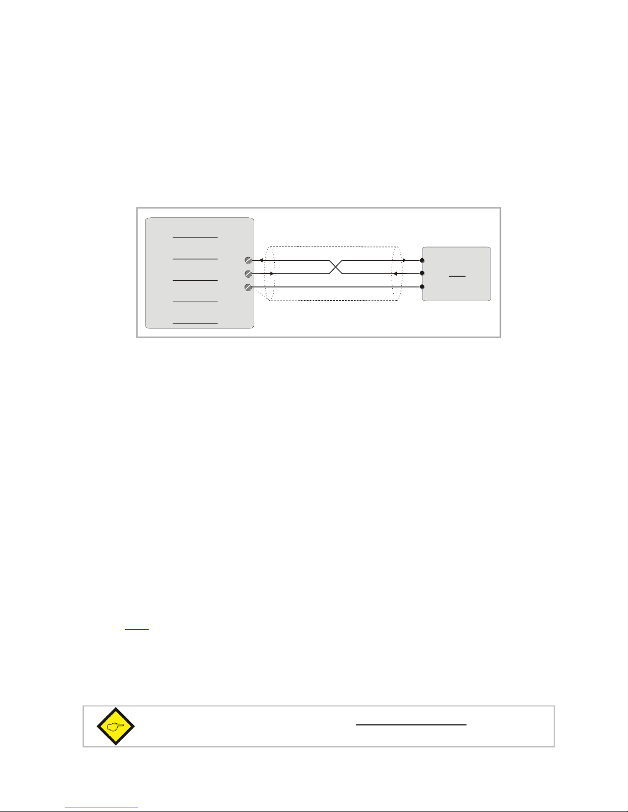
4.10. Serial Interface
The serial RS232 interface in general may be used
for easy setup and commissioning of the units (with use of the OS32 operator software)
to change settings and parameters by PC or PLC during the operation
to read out internal states and actual measuring values by PC or PLC
The subsequent drawing shows how to link the monitor with a PC, using the standard
9-pin SUB-D-9 connector
2
3
5
RxD RxD
TxDTxD
GND
Screen
PC
DZ 260
DZ 261
DZ 266
DZ 267
DZ 269
15
(Sub-D-9)
16
14
4.11. Relay Outputs K1 –K3 (DZ260 and DZ267 only)
The units provide three programmable relay outputs (all dry changeover), providing a switching
capability of 30 V / 2 A DC or 125 V / 0.6 A AC or 230 V / 0.3 A AC. Both, switching
characteristics and monitoring function may be programmed for each of the relays individually.
4.12. Transistor Outputs K1 –K3 (DZ261 and DZ269 only)
The units provide three outputs with programmable switching characteristics.
K1 –K3 are fast-switching and short-circuit-proof transistor outputs with a switching capability of
5 ... 30 V / 350 mA each. The switching voltage of the outputs must be applied remotely to the
Com+ input (terminal 22). Both, switching characteristics and monitoring function may be
programmed for each of the outputs individually.
4.13. Scalable Analog Output (DZ260, DZ261 and DZ266 only)
The units provide a voltage output with a +/-10 V range (max. load 2 mA) and a current output
with ranges 0 / 4 ... 20 mA (burden 0 –270 Ohm), however only one of the two can be used at a
time. Beginning and end of the desired conversion range can be set by the operator menu (see
section 7.2.7). The common potential of both outputs refers to GND.
The total resolution is 14 bits. A settling time of approx. 200 µs. is required. The overall response
time of the analog outputs primarily depends on the selected Sampling Time setting. After
volatile jumps of the input signal, the analog outputs may need up to two Sampling Time cycles
(plus 200 µsec.) to stabilize.
Important note: “voltage out” and “current out” must not be used together.
Please do never connect mA and V simultaneously!

Dz260_05a_oi_e.doc / Dez-16 Page 15 / 40
5. LCD Display and Keys
The units provide a back-lit LCD display with 2 lines at 16 characters each, and four keys for setup
and command control.
During the setup procedure the LCD display indicates the menu with all parameter texts and the
set values of the parameters.
During normal operation, the LCD display indicates the following information:
Actual speed value
Input frequency, scaled in user units
+156.5 Hz
I: LH O: COO +47 %
Analogue output (not with DZ267, DZ269)
Actual output level in % of full scale
O: Outputs (not with DZ266)
Actual switching states of relays/transistor outputs
(Rel1, Rel2, Rel3)/(out1, out2, out3)
C = Closed, O = Open
I: Inputs
Actual logical state of inputs
(Control1, Control2)
L = Low, H = High
The "Display Menu" allows free scaling of the speed measuring values and the speed-related
parameters to any kind of engineering units.

Dz260_05a_oi_e.doc / Dez-16 Page 16 / 40
6. Keypad Operation
A summary of all parameters and a detailed description of parameter functions is available under
section 6.
For all operation, the units provide four keys which subsequently will be named as shown below:
PROG
UP
DOWN
ENTER
The key functions depend on the actual operating state of the units. Basically we have to
distinguish between Normal Operation and Setup Operation
6.1. Normal Operation
While in normal operation state, the units monitor the speed according to the selected
operational parameters and settings. Each of the front keys provides the command functions as
attached to it upon setup in the "Command Menu"
6.2. Keypad Interlock
There is a 3-stage conception to protect the keys against unauthorized changes of the
configuration respectively against activation of commands.
Stage
Protected
Range
Protection
by
Key Operations
Change of Parameters
Commands
1
---
---
permitted
permitted
2
Menu
Password upon
activation of menu
Protection of selectable parts of the menu
via password
permitted
3
Keyboard
Hardware-Latch 1
interlocked
permitted
Hardware Latch 2
All functions interlocked
The "Key Pad" menu allows to define an individual password for each group of parameters. This
function can be used to provide individual access rights to different operators. Upon access to an
interlocked section the unit asks for the corresponding password. If the correct password is not
entered in time, the unit denies access and automatically returns to normal operation.
The hardware latch function can be activated and deactivated by one of the Control Inputs, or by
means of serial access to the corresponding locking register.
Using the Hardware Latch function may accidentally cause a total locking of all
functions, when the Control Inputs characteristics have been set inauspiciously.
In this exceptional case you can release the key functions again by either
a) applying the correct logical state (High or Low) to the inputs
b) or resetting the parameters to their default values (see section 6.6)
c) or change the parameters being responsible for the locking by PC
P

Dz260_05a_oi_e.doc / Dez-16 Page 17 / 40
6.3. General Setup Procedure
To change over from normal operation to the setup state, please keep down the PROG key for at
least 2 seconds. After this the menu appears and you can select one of the menu groups.
Inside each group you can select the desired parameter and edit the setting according to need.
After this you are free to edit more parameters, or to return to normal operation.
The function of the different keys during setup is shown in the table below.
Key
Menu Level
Parameter Level
Setting Level
PROG
Save settings and return
to normal operation
Return to Menu Level
Check entry, store result,
then go back to Parameter
Level
UP
Switch over to next menu
Select next parameter
Increment the highlighted
digit or scroll the setting
upwards
DOWN
Go back to previous menu
Select previous parameter
Decrement the highlighted
digit or scroll the setting
downwards
ENTER
Switch over to the
Parameter Level of the
current menu
Switch over to
Setting Level
Shifts the highlighted digit
one position to the left, or
from utmost left to utmost
right
6.4. Changing Parameters on the Setting Level
With signed parameters, the front digit can only be changed between „+“ (positive) and „-„
(negative). The subsequent example explains how to change a parameter from originally 1024 to
a new value of 250 000.
The example assumes that you are already on the Setting Level, i.e. you have already selected
the corresponding parameter and read its actual value on the display. Highlighted (blinking) digits
are marked by background colour and indicate the cursor position.

Dz260_05a_oi_e.doc / Dez-16 Page 18 / 40
No.
Display
Key action
Comment
00
001024
The actual value 1024 is displayed, with
the last digit blinking
01
4 x
Change last digit to 0
02
001020
Shift cursor to left
03
001020
2 x
Change highlighted digit to 0
04
001000
2 x
Shift curser to left by 2 positions
05
001000
Change highlighted digit to 0
06
000000
Shift cursor to left
07
000000
5 x
Change highlighted digit to 5
08
050000
Shift cursor to left
09
050000
2 x
Change highlighted digit to 2
10
250000
Save new setting and return to
Parameter Level
6.5. Return from the Menu, Time-Out Function
At any time the PROG key changes the Menu by one level backwards or fully back to the normal
operation mode. The menu also switches automatically one level backwards, every time when for
10 seconds no key has been touched (Time-Out-Function).
6.6. Reset all Parameters to Factory Default Values
If applicable, the whole set of parameters can be reset to factory default values (e.g. because a
code for the keypad interlocking has been forgotten, or because the unit does no more work
correctly for reasons of bad settings). All default values are indicated in the following parameter
tables.
To execute this Reset procedure, you have to take the following steps:
Power the unit down
Press
and
simultaneously
Switch power on with both keys held down
When execute this action, please be aware that all parameter settings
will be lost and the whole setup procedure must be repeated!

Dz260_05a_oi_e.doc / Dez-16 Page 19 / 40
7. Menu Structure and Parameter Description
All parameters are combined to groups, arranged in several menus. Settings are only necessary
for parameters which are really relevant for the individual application.
7.1. Survey of Menus
This section provides an overview of the menus and their assignments to the different functions
of the units. The menu names are printed bold, and associated parameters are arrayed directly
under the menu names.
Menu texts are in English language, according to the presentation on the LCD display
Preselect.-Menu*
Encoder-Menu
Ser.Readout Menu
Special-Menu
Preselection 1
Encoder Proper
Multiplier
Linear Mode**
Preselection 2
Direction
Divider
Freq. Control
Preselection 3
Sampling Time
Offset
Input Filter
Wait Time
Filter
Set Value
Key-Pad-Menu
Command-Menu
***
Analog-Menu**
Serial-Menu
Protect Menu M01
Key Up Func.
Analogue Format
Unit Number
Protect Menu M02
Key Down Func.
Analogue Start
Serial Baud Rate
Protect Menu M03
Key Enter Func.
Analogue End
Serial Format
…
Input 1 Config.
Analogue Swing
Serial Protocol
Protect Menu M09
Input 1 Func.
Analogue Offset
Analogue ABS
Serial Timer
Protect Menu M10
Input 2 Config.
Register Code
Protect Menu M11
Input 2 Func.
Switching-Menu*
Linear.-Menu**
Display-Menu
Pulse Time 1
P1(x)
Up-Date-Time
Pulse Time 2
P1(y)
Display Mode
Pulse Time 3
P2(x)
Encoder Factor
Hysteresis 1
P2(y)
Multiplier
Hysteresis 2
..
Hysteresis 3
P14(x)
Preselect Mode 1
P14(y)
Preselect Mode 2
P15(x)
Preselect Mode 3
P15(y)
Output Polarity
Start up Mode
Start up Relay
(*) not relevant with DZ266
(**) not relevant with DZ267, DZ269
(***) partially inactive with DZ266
Lock Relay
Standstill Time

Dz260_05a_oi_e.doc / Dez-16 Page 20 / 40
7.2. Parameter Descriptions
7.2.1. Preselection’s
Preselection parameters are not relevant for model DZ266
These parameters assign the desired switching points to the relays/outputs. The preselection’s
use the same engineering units as the display of the actual speed (see Display-Menu).
Preselection Menu
Code
Setting Range
Default
Preselection1
Switching point of relay 1/ out 1 (engineering units)
„00“
-1 000 000.0 ... +1 000 000.0
100.0
Preselection2
Switching point of relay 2/ out 2 (engineering units)
„01“
-1 000 000.0 ... +1 000 000.0
200.0
Preselection3
Switching point of relay 3/ out 3 (engineering units)
„02“
-1 000 000.0 ... +1 000 000.0
300.0
7.2.2. Definitions for the Encoder or Speed Sensor
Encoder-Menu
Code
Setting Range
Default
Encoder Proper
Encoder properties
„A0“
0 … 11
0
0
A/B/90° quadrature, RS422 or HTL differential
1
A/B/90° quadrature, single-ended, HTL NPN*
2
A/B/90° quadrature, single-ended, HTL PNP
3
A/B/90° quadrature, single-ended, TTL level
4
A=Impulse, B=direction, RS422 or HTL differential
5
A=Impulse, B=direction, single-ended, HTL NPN*
6
A=Impulse, B=direction, single-ended, HTL PNP
7
A=Impulse, B=direction, single-ended, TTL level
8
Channel A only, RS422 or HTL differential
9
Channel A only, single-ended, HTL NPN*
10
Channel A only, single-ended, HTL PNP
11
Channel A only, single-ended, TTL level
Direction
Definition of the direction of rotation with quadrature encoders
„A1“
0, 1
0
0
forward when A leads B
1
forward when B leads A
(*) With settings HTL / NPN the input terminals are connected to the power supply voltage of
the unit (+24 V) via internal pull-up resistors. For this reason it is advisable to first set the
encoder properties correctly, prior to connecting TTL encoders to the unit.
Setting HTL / NPN is also suitable for use with NAMUR (2-wire) proximities.
(connect the positive wire of the sensor to the input terminal and the negative wire to GND)
This manual suits for next models
5
Table of contents
Other Motrona Monitor manuals


Popular Monitor manuals by other brands


ViewSonic
ViewSonic VX1962wm - 19" LCD Monitor Service manual

Philips
Philips 4CM2299 operating instructions

Sony
Sony SDM-HS74 Service manual

Austin Hughes Electronics
Austin Hughes Electronics CyberView RP-1020QD brochure

Philips
Philips 150S6FB/00 Service manual

Panasonic
Panasonic TH-65PHD8BK Service manual