8
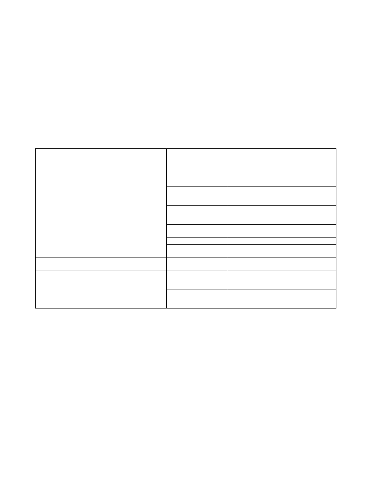
1.3 Troubleshooting Guide for LCD
Symptom/Condition PROBABLE CAUSE CORRECTIVE ACTION
Air/cable setting is not
correct Follow the set up procedures in LCD manual.
TV signal source is not
supplied.
- Check if the TV signal source is correctly supplied
to A/D PCB from external source.
- Make sure the cable is properly secure.
- If external TV signal is correct, try to connect the
coaxial cable directly to the internal connector in AD
PCB of Console to check whether the internal
cables are wrong or not.
75 ohm coaxial cable is bad. Replace 75 ohm coaxial cable.
Snow and noise are scattering on LCD screen. Any picture is
not found even though channel-up button or channel-down
button is pressed.
A/D Board is damaged. Replace A/D Board with new one.
LCD screen is uniformly white Internal cable connection is
loose or disconnected.
Check if the connection between LCD screen and
A/D Board is tight. In other word, LVDS cable shown
in picture.
Vertical large white-stripe or Vertical stripe block on LCD
screen Problem with LCD screen Replace LCD screen
When LCD power is turned on by
pressing TV on/off, “VIDEO”, “S-VIDEO”
or “ANALOG” appears temporarily and
then disappears on the left upper corner
of LCD screen.
TV mode is not set-up.
1) Whenever you press Volume down button, words
are displayed in following order on the left upper
corner of LCD screen.
“ANALOG”=>”VIDEO”=>”S-VIDEO”=>”TV”
2) Press the button until “TV” is displayed.
3) As soon as “TV” is displayed, snow and noise will
be scattering on LCD screen or any picture will be
captured.
LCD screen is dark
or black.
When LCD power is turned on by
pressing TV on/off, “VIDEO”, “S-VIDEO”
or “ANALOG” is NOT displayed on the LCD Power Supply has a
problem. Power Supply is
used for supplying 12 VDC
Check if LCD Power supply is normally operated or
LED lamp on Power supply body is turned on.
If LED is off,