MOUNT PRO PR5001 User manual

PR5001 1.5~8kg
(3.3~17.6lbs)
RATED
Single Monitor Counterbalance Desk Mount
Instruction Manual
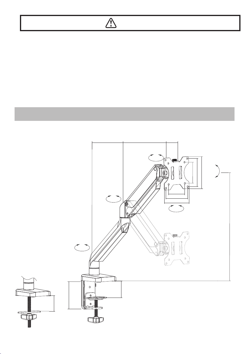
PRODUCT LINE GRAPH
75mm
100mm
114mm
75mm
100mm
114mm
±180°
±90°
+45°
-45°
min10~max85mm
100mm
mm514xam~531nim
60mm
min220~max275mm
170mm
±180°
±180°
min10~max85mm
02
WARNING!
If you do not understand these instructions or have doubts about the safety of the installation, assembly or use of
Before starting assembly, verify all parts are included and undamaged. Improper installation may cause damage or
serious injury. Do not use this product for any purpose that is not explicitly specied in this manual. Do not exceed
weight capacity. We cannot be liable for damage or injury caused by improper mounting, incorrect assembly or
inappropriate use.
This product contains small items that could be a choking hazard if swallowed. NOT FOR CHILDREN UNDER 3 YEARS.
ADULT SUPERVISION IS REQUIRED.

Components
Hardware
PACKAGE CONTENTS
B (x1)
VESA Plate
H (x1)
Support Plate
I (x1)
Security Screw
K (x1)
Wingnut
J (x5)
Bolts
C (x1)
Clamp Base
Support
D (x1)
Clamp
E (x1)
Base Support Cover
F (x1)
Long Screw
G (x1)
Base Support
M4x12mm (x4)
M-A
Screws
M4x16mm (x4)
M-B
Screws
M6x12mm (x4)
M-C
Screws
M6x16mm (x4)
M-D
Screws
D6 (x4)
M-E
Washer
5mm(x4)
M-F
Spacer
L (x4)
Pad
M (x1)
4mm Allen Wrench
N (x1)
6mm Allen Wrench
03
A (x1)
Monitor Stand

OPTION A: Clamp Installation
Install clamp base support (C) onto base of monitor stand (A) with bolts (J)
using provided 4mm Allen wrench (M).
STEP 1 Choose a mounting option
Apply pads (L) to bottom of base to prevent table top from being scratched.
04
A
C
M
J
L
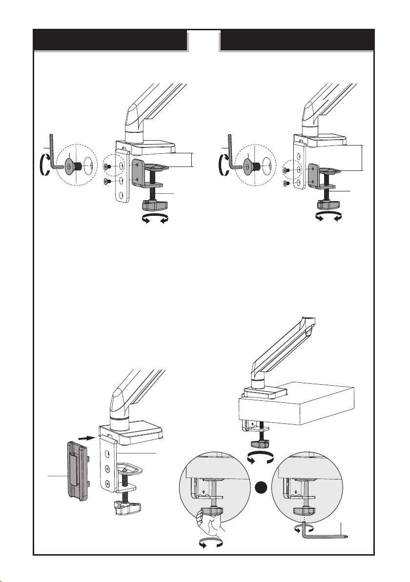
Secure clamp (D) to upper two holes with
bolts (J) using 4mm Allen wrench (M) for
desks with a thickness of 10-55mm.
Secure clamp (D) to lower two holes with
bolts (J) using 4mm Allen wrench (M) for
desks with a thickness of 50-85mm.
Adjust the Mount to the Desktop
Thickness 10-55mm
Adjust the Mount to the Desktop
Thickness 50-85mm
Attach base support cover (E)to clamp base support (C). Tighten the clamp to the
desktop using the plastic knob or by using 6mm allen wrench(N).
05
50-85mm
D
MJ
10-55mm
D
MJ
N
OR
E
C
Table of contents


