Moxy MT 26 User manual
Engine
SHOP MANUAL MT26-31 - 06.2005
Tier-3 710655- Ch 1 page 1
Chapter 1
Engine

SHOP MANUAL MT26-31 - 06.2005
Engine
Tier-3 710655-
Ch 1 page 2
Chapter 1
Engine
Index
Removal of engine assembly ................................................................ 5
Lifting the engine.........................................................................................................................11
Engine identification............................................................................ 12
Fuel system .......................................................................................... 13
Schematic diagram of the fuel system ........................................................................................13
Overflow valve.............................................................................................................................13
General .......................................................................................................................................14
FUEL...........................................................................................................................................14
Fuel filter .....................................................................................................................................15
Water separating prefilter............................................................................................................15
Feed pump ..................................................................................................................................17
Diagnostic prosedure .......................................................................... 18
Use of diagnostic kit, machine ....................................................................................................18
Measurement ..............................................................................................................................21
Ecom standard settings code......................................................................................................24
Engine control unit, ECU ..................................................................... 27
Wiring and cable duct..................................................................................................................28
Throttle position sensor...............................................................................................................28
Positions of sensors for ECU ......................................................................................................29
Diagnostic lamp and switch.........................................................................................................31
Fault codes..................................................................................................................................32
How to read fault codes from the ECU control unit .....................................................................33
Flash codes tables ......................................................................................................................35
Overview of flash codes for coordinator......................................................................................37
Renewing the control unit............................................................................................................39
Removing the ECU wiring ..........................................................................................................40
Cylinder head ....................................................................................... 44
Special tools................................................................................................................................44
Cylinder head, parts view............................................................................................................45
Valve mechanism ........................................................................................................................46
Dismantling ................................................................................................................................51
Renewing the valve stem seal.....................................................................................................51
Replacement of valve seats ........................................................................................................52
Machining the valve seats insert .................................................................................................53
Renewing the valve guides ........................................................................................................55
Renewing PDE unit injector sleeves ...........................................................................................56
Assembly ....................................................................................................................................57
Fitting ..........................................................................................................................................57
PDE Injectors........................................................................................ 58
Fitting the PDE injector ...............................................................................................................58
Adjusting unit injectors ................................................................................................................62
Adjusting the valve clearance and unit injectors .........................................................................64
Checking, adjusting the PDE32 injector rocker arms (I)..............................................................65
Turbocharger ........................................................................................ 67
General ......................................................................................................................................68
Special tools................................................................................................................................69
Measuring radial clearance and axial clearance ........................................................................70
Renewing the turbocharger.........................................................................................................72
Continuation next page

Engine
SHOP MANUAL MT26-31 - 06.2005
Tier-3 710655- Ch 1 page 3
Pistons and cylinder liners.................................................................. 73
Special tools................................................................................................................................74
Connecting rods..........................................................................................................................75
Removing and dismantling connecting rods and pistons ............................................................76
Renewal of bearing bushing in connecting rod ...........................................................................78
Pistons ........................................................................................................................................80
Assembling piston and connecting rod .......................................................................................82
Cylinderblock........................................................................................ 83
Cylinder liner ...............................................................................................................................83
Removing the cylinder liners .......................................................................................................85
Measuring the cylinder liner height .............................................................................................86
Fitting the cylinder liners .............................................................................................................87
Fitting the piston and connecting rod ..........................................................................................88
Flywheel and flywheel housing........................................................... 90
Special tools................................................................................................................................91
Removing the flywheel................................................................................................................91
Renewing the rear crankshaft seal..............................................................................................93
Removing the flywheel housing ..................................................................................................93
Fitting flywheel housing...............................................................................................................94
Fitting the flywheel ......................................................................................................................96
Timing gears......................................................................................... 97
Gear drive ...................................................................................................................................97
Belt drive collant pump, generator and AC compressor..............................................................98
Renewing the seal in the front cover...........................................................................................99
Crankshaft damper....................................................................................................................100
Timing gear, view exploded.......................................................................................................101
Special tools ....................................................................................... 102
Crankshaft seal .........................................................................................................................103
Timing gear cover......................................................................................................................105
Intermediate gear......................................................................................................................107
Crankshaft gear ........................................................................................................................108
Camshaft gear ..........................................................................................................................109
Camshaft ............................................................................................ 110
Crankshaft .......................................................................................... 112
Lubrication system ............................................................................ 114
Oil pump....................................................................................................................................114
Lubrication oilways ..................................................................................................................115
Oil pressure...............................................................................................................................116
Oil cooler, engine .....................................................................................................................117
Oil cooler view...........................................................................................................................118
Renewing seals.........................................................................................................................119
Oil filter......................................................................................................................................120
Centrifugal oil cleaner ....................................................................... 121
Dismantling and assembly ........................................................................................................122
Cooling fan ......................................................................................... 126
Continuation next page

SHOP MANUAL MT26-31 - 06.2005
Engine
Tier-3 710655-
Ch 1 page 4
Cooling system .................................................................................. 127
View of the cooling system........................................................................................................127
Circulation .................................................................................................................................128
View of the radiator system.......................................................................................................128
Disassemble the cooling unit ....................................................................................................129
Thermostat and thermostat housing .........................................................................................131
Thermostat................................................................................................................................132
Coolant pump............................................................................................................................133
External cleaning ......................................................................................................................137
Internal cleaning........................................................................................................................137
Specifications..................................................................................... 138
General information...................................................................................................................138
Cylinder head............................................................................................................................140
Turbocharger ............................................................................................................................142
Pistons and cylinder liners ........................................................................................................142
Connecting rods........................................................................................................................143
Flywheel and flywheel housing .................................................................................................143
Timing gear ...............................................................................................................................144
Lubrication system ...................................................................................................................145
Troubleshooting tables ..................................................................... 146
White smoke .............................................................................................................................146
White smoke, water vapour.......................................................................................................146
Black smoke when running/under load .....................................................................................147
Black smoke on starting ............................................................................................................148
Blue smoke ...............................................................................................................................148
Fuel in the oil.............................................................................................................................148
Oil in coolant ............................................................................................................................149
Coolant/water in oil ...................................................................................................................150
Low oil pressure........................................................................................................................151
High oil pressure (Engine warmed up)......................................................................................153
Abnormal wear (liner, piston rings, etc.)....................................................................................153
Vibration, no driven components engaged................................................................................154
Delivery pipe fractures ..............................................................................................................155
External corrosion on cylinder liner ...........................................................................................155
Engine difficult to start...............................................................................................................155
Fluid stroke................................................................................................................................156
Knocking noise..........................................................................................................................156
High oil consumption.................................................................................................................158
High fuel consumption...............................................................................................................159
Low compression ......................................................................................................................159
Low engine output.....................................................................................................................159
Hot engine.................................................................................................................................161
Cold engine...............................................................................................................................162
Coolant loss ..............................................................................................................................162
Polluted coolant.........................................................................................................................162
Engine heater............................................................................................................................163
High oil temperature..................................................................................................................163
High exhaust temperature.........................................................................................................164
Low charge air pressure............................................................................................................164
Low fuel pressure......................................................................................................................165
Low system voltage...................................................................................................................165
High system voltage..................................................................................................................165
External oil leakage...................................................................................................................166
External fuel leakage ................................................................................................................166
External coolant leakage...........................................................................................................167
Oil pressed out via crankcase ventilation..................................................................................167
Turbocharger breakdown ..........................................................................................................167

Engine
SHOP MANUAL MT26-31 - 06.2005
Tier-3 710655- Ch 1 page 5
Removal of engine assembly
NOTE!
Place the dump truck on level ground and apply parking brake
Apply articulation lock.
Turn off main switch in battery case.
Raise the dump body and lock it with the safety support.
Raise the tiltable cab and lock it with the safety support
Drain engine coolant
Look in OPERATION & MAINTENANCE MANUAL chapter 2 for instructions.
Take away the cab bolt, left and right hand side.
Nv 46 mm
Turn the direction valve on the pump in lifting up
position.
Place wheel chocks to the front wheel
With the handle, pump and raise the cab.

SHOP MANUAL MT26-31 - 06.2005
Engine
Tier-3 710655-
Ch 1 page 6
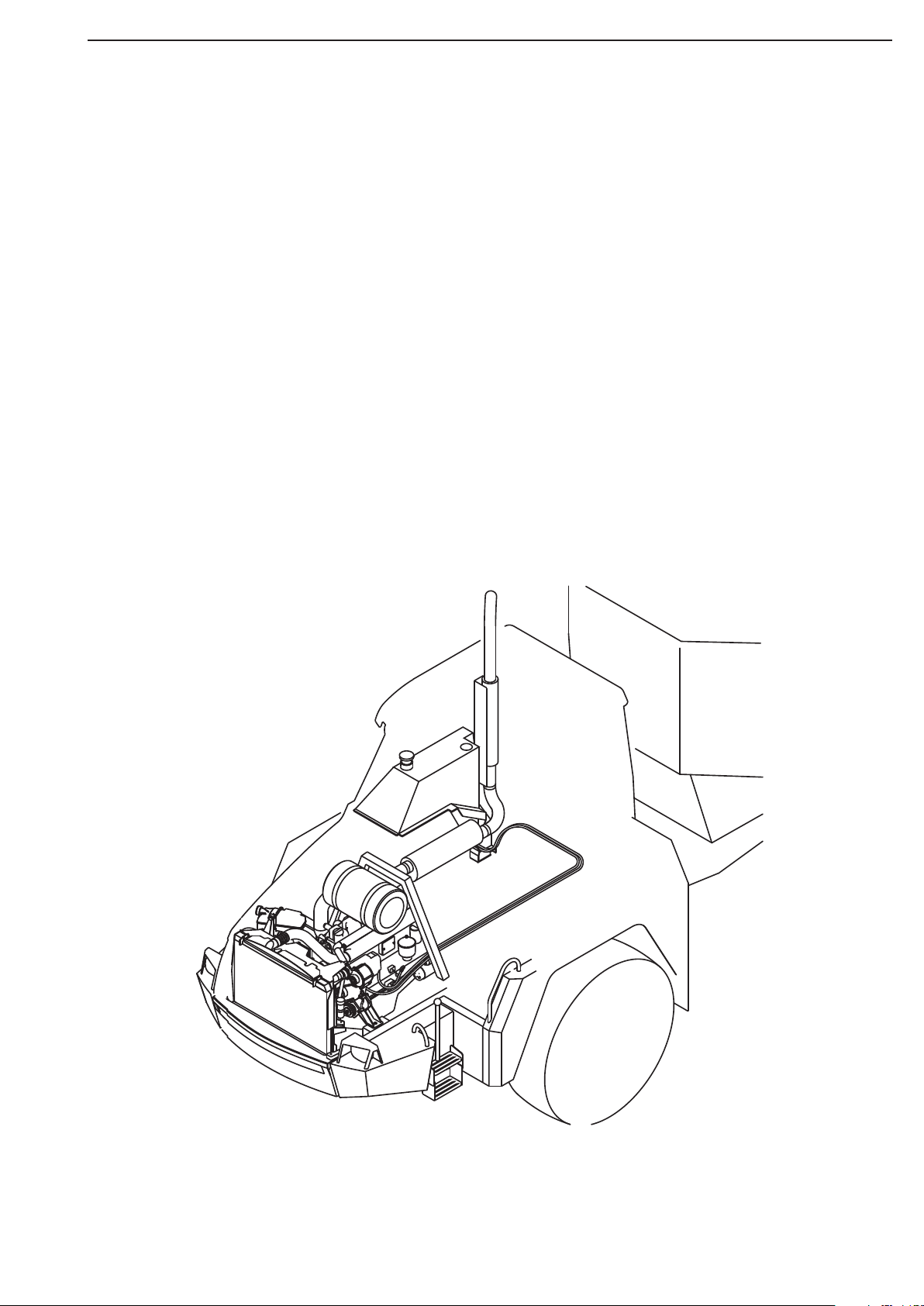
Left side:
1
Disassemble the cab pump unit from the air filter stand.
2
Remove the water hose from the pipe socket.
3
Remove the fuel hoses (3 pcs) and
4
Disassemble screws from filter stand bracket
Right side:
1
Unscrew the hose clamps and remove the pipe bend,
filter - turbo
2
Disconnect the oil hose from engine brake cylinder and bracket
disassemble the other end at left side on the magnetic valve
3
Hook up the filter stand in lifting device.
4
Screw off the fastening bolt for filter stand,
left and right hand side
2
1
1
4
3
Disconnect the brake hose from the magnetic valve.
(Left side behind the cab bracket)
1
2
34
Engine
SHOP MANUAL MT26-31 - 06.2005
Tier-3 710655- Ch 1 page 7
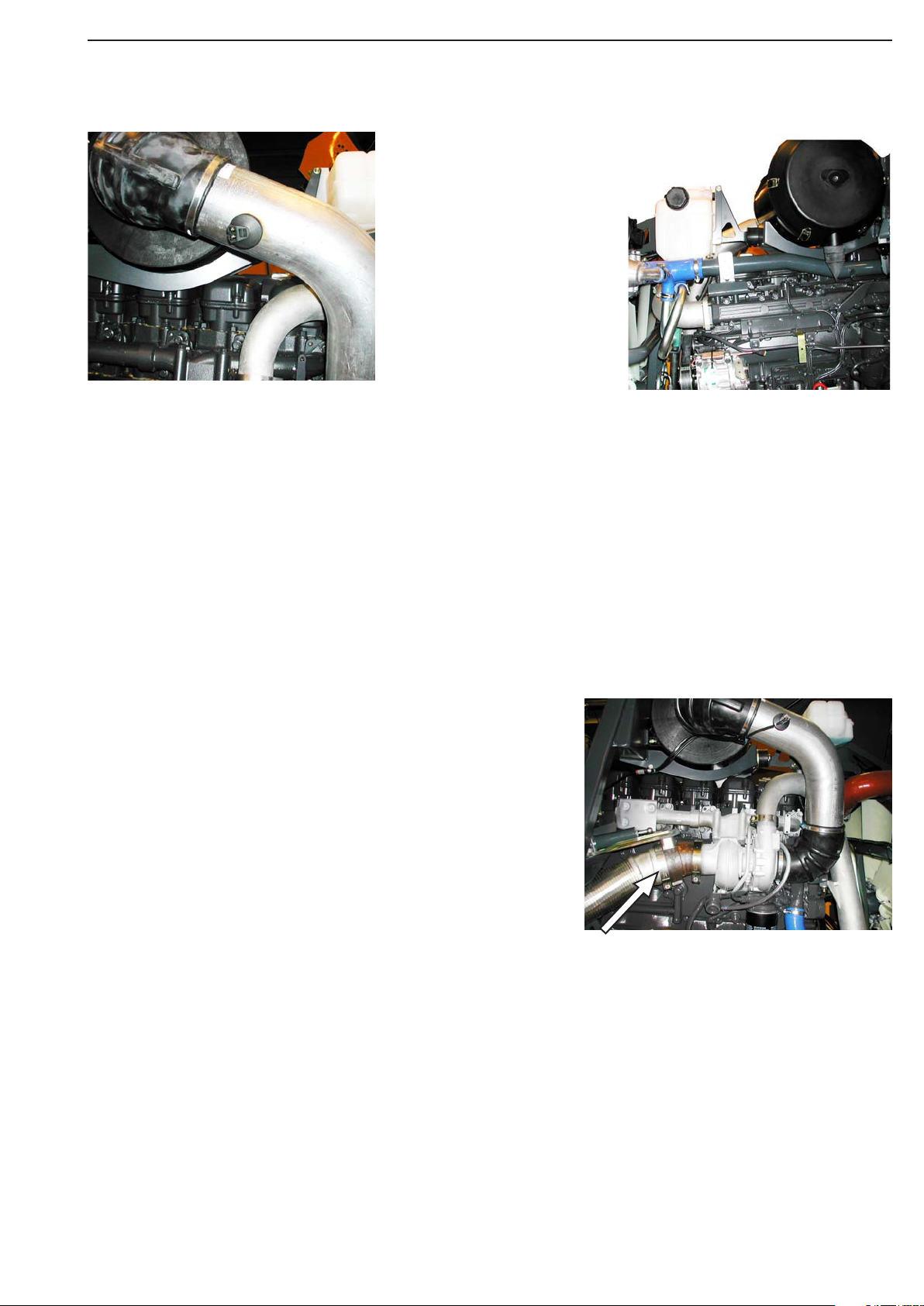
Disconnect the exhaust pipe from the turbo pipe bend.
Disasssemble the cable to the Air filter sensor.
Disassemble the clamps for the wiring on the filter stand

SHOP MANUAL MT26-31 - 06.2005
Engine
Tier-3 710655-
Ch 1 page 8
Slack the transmission belt.
Disassemble the ground wiring.
Detach the Air Cond. compressor with the hoses on, from the
engine. Check that all of the clamps are undone.
Place the Air condition compressor on the left while the engine is
dismount.
Disconnect the hose from the termostathousing,
the pipe between the air cooler and the engine air inlet.
Disconnect bracket for the air pipe and bracket between engine
and fan rack
Disconnect the outlet pipe bend from turbo, and the inlet water
hose from the transmission cooler.
Disconnect the retur hose. (Engine - ekspantionstank)
(Quick release coupling)
(Front of the engine, view from the right hand side)
Engine
SHOP MANUAL MT26-31 - 06.2005
Tier-3 710655- Ch 1 page 9
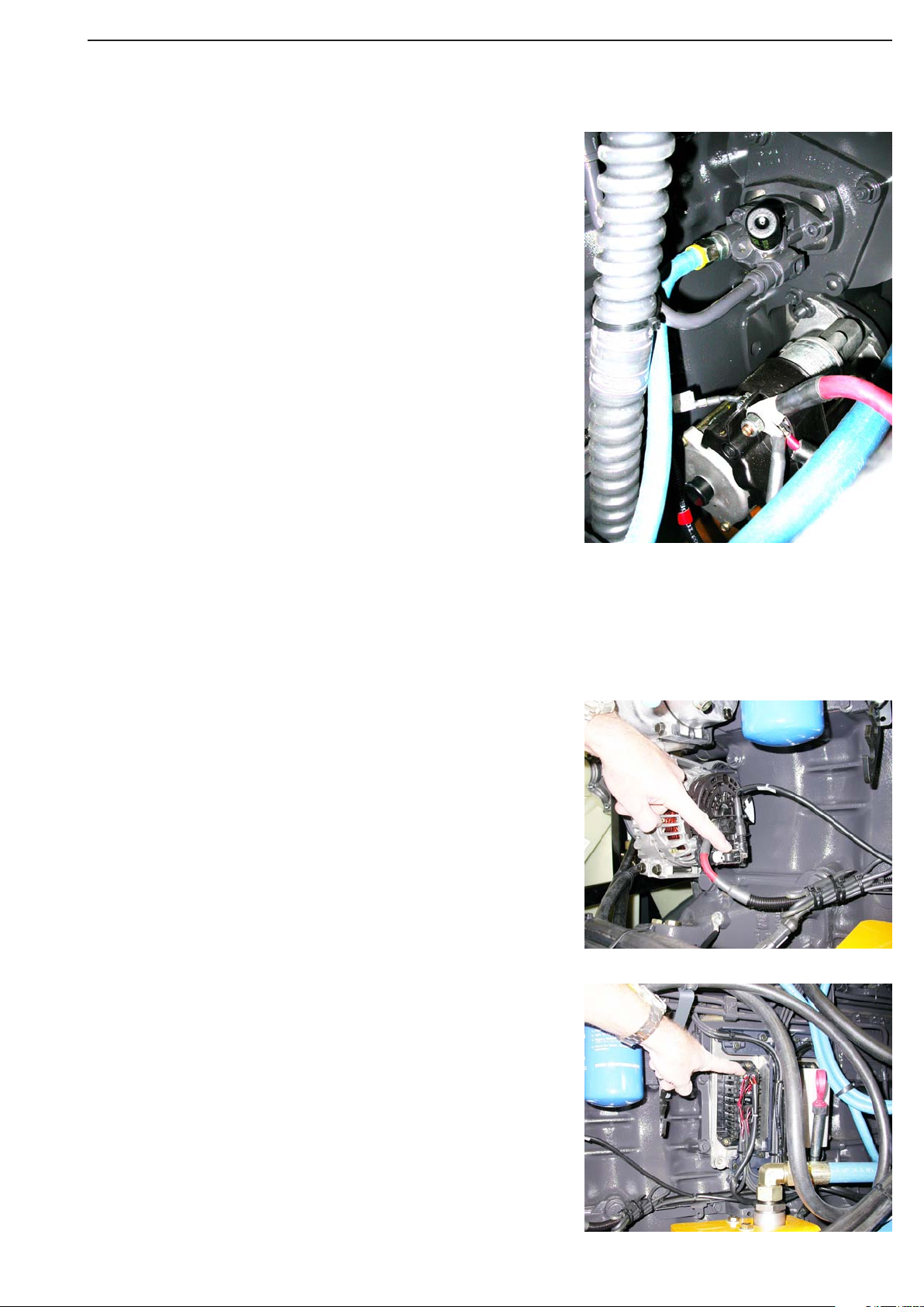
Disconnect the contact on the dynamo.
Remove the cover and disconnect the electrical contact from the
engine ECU -S6 control unit
Disconnect the cables between starter motor and the frame
SHOP MANUAL MT26-31 - 06.2005
Engine
Tier-3 710655-
Ch 1 page 10
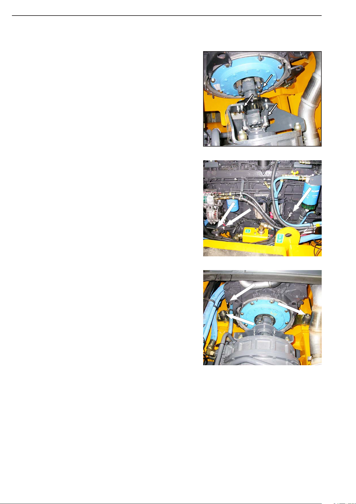
1
Disassemble screw for the ground cable (2 pcs)
2
Left and right hand side, disassemble 3 screws on the engine
mounting bracket.
2
1
1
2
1
Disassemble the hose clamp bracket.
2
Unscrew the engine bracket bolt left and right hand side.
1
2
Drive shaft
Remove safety atcher.
Remove driveshaft between transmission and engine coupling,
12
2

Engine
SHOP MANUAL MT26-31 - 06.2005
Tier-3 710655- Ch 1 page 11
- Fasten the lifting chain 8373 to the rear
lifting eyes.
- Fasten the lever block 8394 to the front
lifting eye.
With attention, lift the engine out from the frame
Note:
The lifting eyes are sized to cope
with a maximum angle of 30°.
Lifting the engine
Note:
The engine lifting eyes are designed
for lifting the engine only, not the
engine together with its ancillary
equipment (alternator, gearbox etc.)
or fram
8394 8373
Lever block Lifting chain

SHOP MANUAL MT26-31 - 06.2005
Engine
Tier-3 710655-
Ch 1 page 12
Engine identification
10 © Scania Industrial & Marine Engines 2005-11:1
TYPE DESIGNATIONS
The engine type designation indicates, in the form of a code, the type of
engine, its size and applications, etc.
The type designation and engine serial number are stamped on the right side
of the engine block. See illustration.
DC 9 63 A 02 P
Type
DC Supercharged diesel engine with air-cooled charge air cooler.
Displacement in whole dm3
Performance and certification code
Indicates, together with the application code, the normal gross engine
output.
The actual output setting of the engine is indicated on the engine card.
Application
A For general industrial use
Variant 01-99
Type of regulator
P EMS engine management system with PDE and S6
The engine designation indicates, in the form of a code, the type of
engine, its size and applications, etc.
The type designation and engine serial number are indicated on a
type plate affixed to the right-hand side of the engine.
The engine number is also stamped on the engine block immedi-
ately above the type plate.
Refer to the illustration.
Engine
SHOP MANUAL MT26-31 - 06.2005
Tier-3 710655- Ch 1 page 13
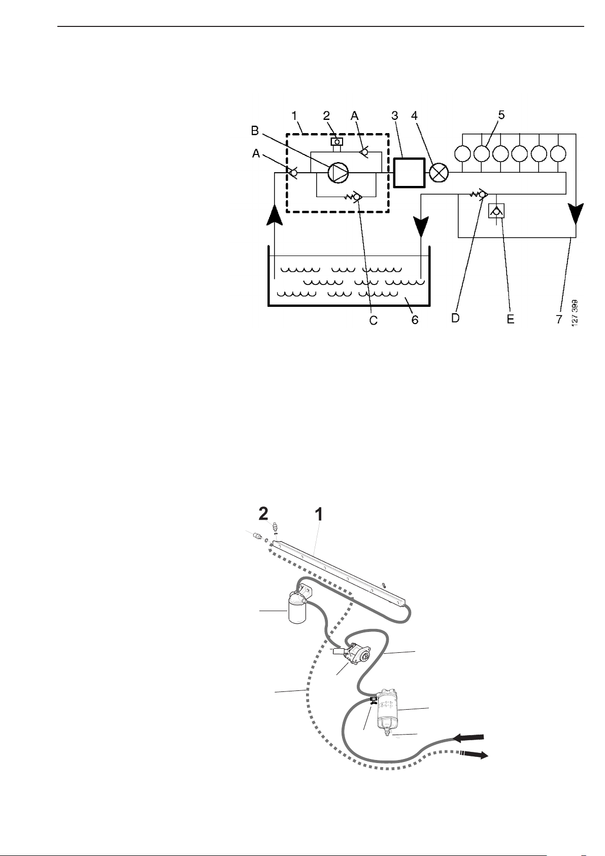
Fuel system
1 Feed pump
2 Hand pump
3 EMS control unit
4 Fuel filter
5 Cylinders
6 Fuel tank
7 Return line for excess fuel
A Check valve
B Gear pump (feed pump)
C Safety valve
D Pressure relief valve
E Drain nipple
Schematic diagram of the fuel system
Overflow valve
The purpose of the overflow valve is to limit the pressure in the
fuel system and continuously vent it. The overflow valve ensures
that the fuel circulates round the system and that there is always
fuel in the injection pump for cooling, lubrication and injection.
Opening pressure is 0.6 - 0.8 bar.
Working pressure is approx. 1 bar.
1 Fuel rail
2 Pressure relief valv
3 Fuel filter
4 Feed pump / hand pump
5 Shut-off cock
6 Oil hose water filter - feedpump
7 Water separating prefilter
8 Retur line
9 Drain valve
Supply from tank
Retur to tank
3
4
8
6
7
59
SHOP MANUAL MT26-31 - 06.2005
Engine
Tier-3 710655-
Ch 1 page 14
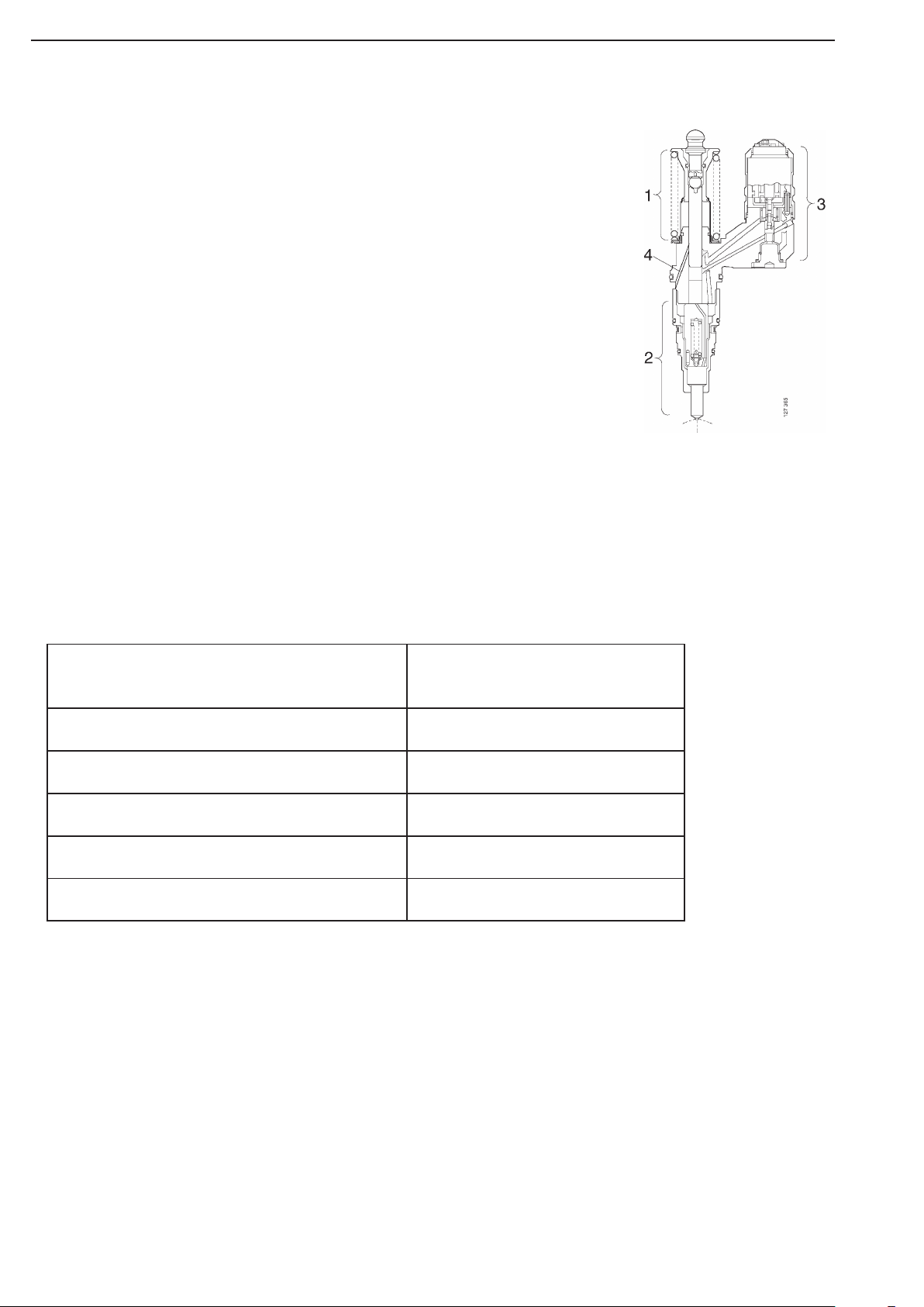
Apart from fuel lines and a fuel tank, a PDE
(Pumpe-Düse-Einheit) fuel system with unit
injectors consists of the following items:
• a feed pump
• a hand pump
• a fuel filter
• one fuel rail.
• a pressure relief valve
• One PDE type unit injector per cylinder.
The fuel system also includes an electronic
control system. The control system includes an
electronic control unit, the unit injector
solenoid valves and sensors.
General
PDE
Diesel fuel oil
The composition of the diesel fuel oil has a great influence on the functioning and
the service life of the engine and the injection system.
The engine output and exhaust emissions are also dependent on the fuel quality.
The diesel fuel must meet European standard EN 590.
The table below shows the requirements for some of the most important properties:
Environmentally favourable fuels (low sulphur fuels)
There are three classes of so called environmentally favourable fuels (SS15 54 35).
Class 1 is sulphur-free and class 2 is low in sulphur. Compared with class 3 (normal fuel), these fuels are less
dense and this reduces engine power output.
FUEL
Property Requirement
Viscosity at 40°C 2.0 - 4.5 mm2/s (cSt)
Density at 15°C 0.82 - 0.86 kg/dm3
Sulphur (concentration by mass) max. 0.3%
Ignitability (CET rating) min. 49
Flashpoint 56°C

Engine
SHOP MANUAL MT26-31 - 06.2005
Tier-3 710655- Ch 1 page 15
Fuel filter
Design
Fuel filter are of single-mounted type. The filter screw on to a
retainer which is bolted to the engine.
The filter consists of a metal container with a folded paper ele-
ment. The filter cannot be dismantled but must be changed as a
complete unit.
The fuel filter has no bleed screw and is bled by undoing plug 4
in the free inlet passage.
Function
Fuel is pumped into the inlet by the fuel pump. It then continues
through passages in the filter retainer to the upper part of the fil-
ter, down through the filter or filters and on to the outlet passage.
From there, the fuel is piped to the injection pump.
1. Filter retainer
2. Filter
3. Gasket
4. Plug
Fuel filter, constituent parts
Note:
Close the shut-off cock when renewing
the filter.
The same intervals between changes apply as
for those for an ordinary fuel filter.
Water separating prefilter
1 Shut-off cock
2 Drain valve

SHOP MANUAL MT26-31 - 06.2005
Engine
Tier-3 710655-
Ch 1 page 16
Temperature dependence of diesel fuel
At temperatures lower than those specified for the diesel
fuel, paraffin wax may precipitate from the fuel and block
filters and pipes. The engine can then loose power or stop.
The diesel fuel is adapted for use in the specific climate of
each country. If a vehicle or an engine is to be operated in a
temperature zone with lower temperature than normal, first
identify the temperature properties of the fuel concerned.
The properties of the fuel when cold can be improved by
adopting one of the following measures before the tempera-
ture drops:
- If the fuel concerned cannot cope with the expected
temperatures, and diesel fuel is not available with the
correct temperature properties, we recommend that
an electric fuel heater is installed as a preventative
measure.
- The low temperature properties of diesel fuel may
be improved by adding kerosene as a preventative
measure. A maximum of 20% may be added. When
refuelling, the kerosene should be added first, so that
it mixes thoroughly with the diesel fuel.
Note:
It is prohibited to use kerosene in engine fuel
in some countries.
- To prevent water in the fuel from freezing and
forming ice, a maximum of 0.5-2% alcohol
(isopropanol) may be added.
Drain fuel tanks and drain or change fuel fil-
ters regularly.
Warning
It is not permitted to mix
kerosene with diesel fuel that is
already adapted for the climate
concerned. This can damage
the
PDE injectors. All use of
paraffin other than kerosene is
forbidden, as it causes engine
damage.
!
Important
It is not permissible to mix
petrol with diesel fuel. In the
long term, petrol may cause
wear to the PDE injectors and it
may also cause damage to the
engine.
Engine
SHOP MANUAL MT26-31 - 06.2005
Tier-3 710655- Ch 1 page 17
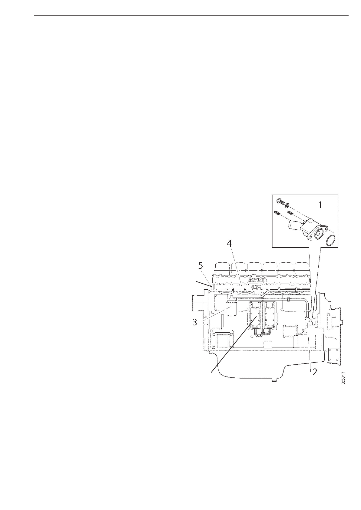
Feed pump
The feed pump 1 draws fuel from the fuel tank and forces it through the fuel filter 3
and into the fuel rail 4.
On the feed pump there is a hand pump 2.
The hand pump is used to vent air from the fuel system.
On the fuel rail there is a pressure relief valve 5.
The pressure relief valve constantly regulates the fuel pressure. When the pressure is too high,
the pressure relief valve opens, so that the excess fuel is returned to the fuel tank.
The fuel rail distributes the fuel to the unit injectors in each cylinder head.
The ECU control unit determines when the unit injectors must inject fuel into the cylinders.
Feed pump renewal
1
Clean the outside of the feed pump.
Remove the suction and pressure lines
from the feed pump.
Fit protective plugs.
2
Unscrew the bolts and remove the feed
pump.
3
Place a new O-ring onto the feed pump and
lubricate with O-ring grease.
4
Fit the feed pump.
5
Connect the suction and pressure pipes.
6
Bleed the fuel system; refer to Bleeding the
fuel system.
7
Start the engine and check for leaks.
1 Feed pump
2 Hand pump
3 Fuel filter
4 Fuel rail
5 Pressure relief valve
6 Bleeder nipple
7 ECU control unit
6
7
SHOP MANUAL MT26-31 - 06.2005
Engine
Tier-3 710655-
Ch 1 page 18
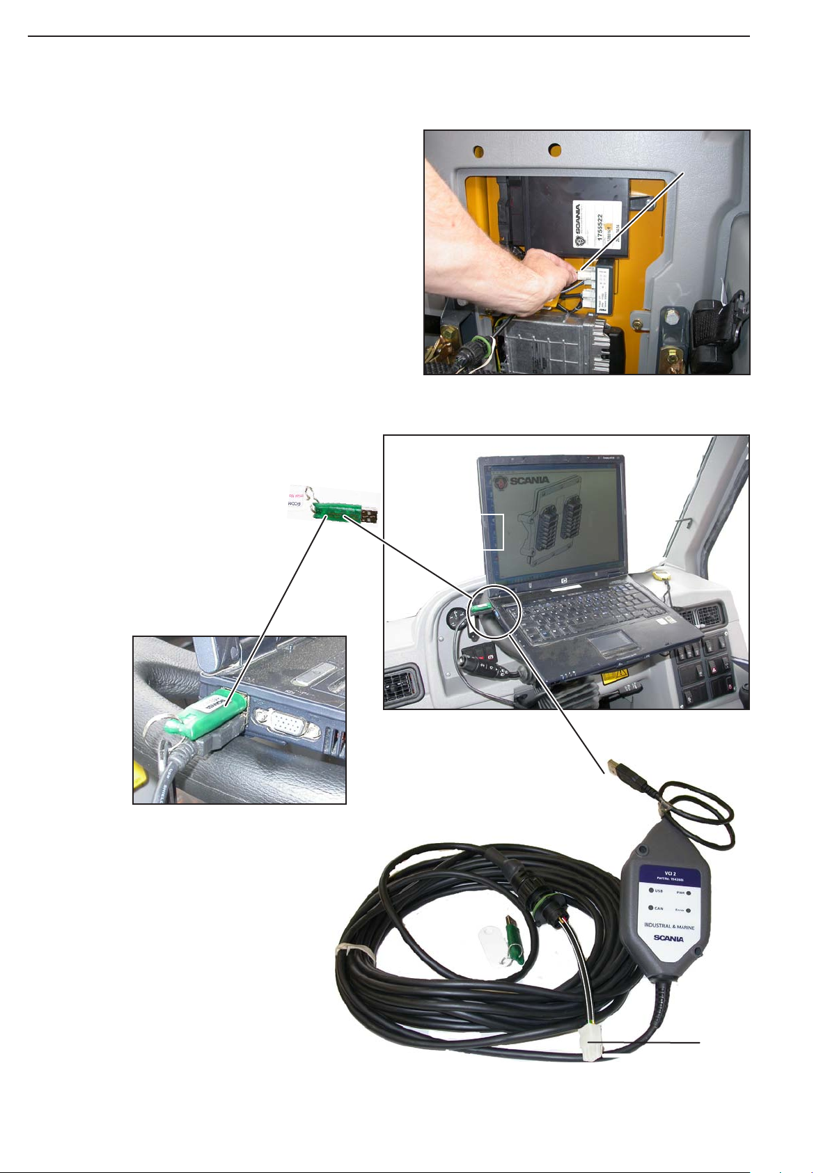
VCI
2
Use of diagnostic kit, machine
2
Install the VCI (ECOM programming unit)
Moxy No.513376
1. Switch on the laptop.
2. Connect the cabel end (1) to the CT1 unit
3. Connect the USB plug (2) to the Laptop
4. Put in the USB key
5. Switch on the ignition key (If read the setting
parameters)
6. Start the engine. (If controlling of the param-
eters)
7. Start on Laptop the engine ECOM program.
4
1
3
Diagnostic prosedure
Engine
SHOP MANUAL MT26-31 - 06.2005
Tier-3 710655- Ch 1 page 19
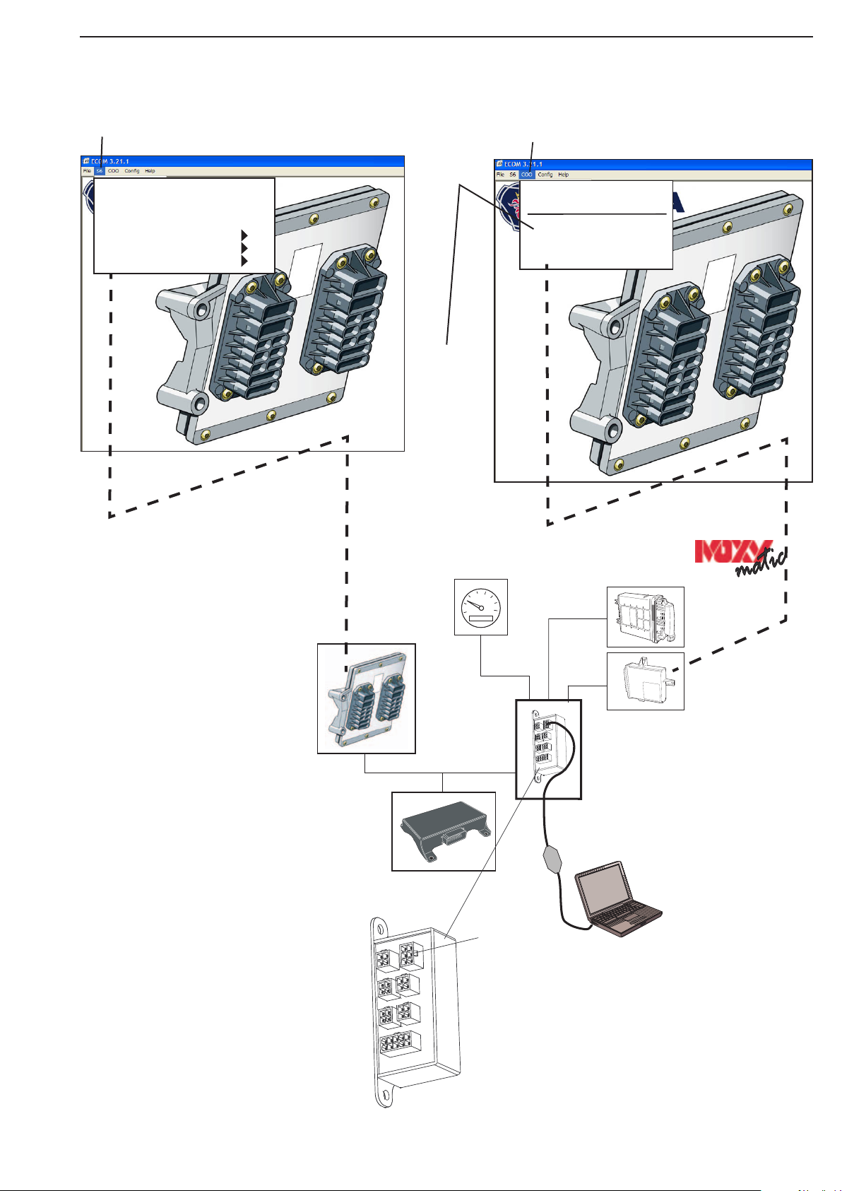
VDO
Tacho EST 37
EMS
COO
IVC4(B)
EMS
S6
Laptop
CT1
(CANbus
conne-
ction)
Test port
CT1
(CANbus connection)
The CT1 has following func-
tions:
Connection point for all CAN-
bus devices on the truck
Contains two independent
CANbus interfaces and han-
dles data transfers between
these buses
Connection point for engine
diagnosis
Handle WDB monitoring and
alarm
Handle histogram logging (In-
formation for service)
Master
Slave
Diagnostic Faul Codes
ECU Identification
Program EEPROM
COO
To read
the fault
codes
in the
coordina-
tor (EMS
COO.)
S6
Diagnostic Fault
Codes
Measurement
ECU Info/ID
Data Logs

SHOP MANUAL MT26-31 - 06.2005
Engine
Tier-3 710655-
Ch 1 page 20
S6
Diagnostic Fault Codes
Measurement
ECU Info/ID
Data Logs
E2
Engine Test
Read out fault codes
Measuring of valves
Adjusting of parameters
Other manuals for MT 26
1
This manual suits for next models
1
Table of contents
Other Moxy Truck manuals


