Utilimaster Aeromaster 1997 User manual

Body
Wiring
Manual
1997–2002 Aeromaster
on Ford Chassis
1997–2002 Aeromaster
on Ford Chassis
Body
Wiring
Manual

2 Aeromaster on Ford Chassis—Body Wiring Manual
Read First: Top Tips on Using This Online Manual
Browse pages with Bookmarks (hyperlinks) or Thumbnails
Bookmarks, at the left of the screen, are hyperlinks to document pages. From any page
in this document, you can use bookmarks to jump to any section heading.
To jump to a topic by using its bookmark, point to the bookmark name, and when the
arrow becomes a pointing hand, click on the name. If a triangle (or + sign) appears to
the left of the bookmark, click the triangle (or + sign) to show or hide subordinate
bookmarks.
Thumbnails are visual icons of the actual pages. fter selecting the thumbnail view button
( crobat Reader ver. 3.0) or tab (ver. 4.0/5.0; “Page” tab in 6.0), you can quickly browse for parts
sections just by the “look” of the page. Click on the appropriate thumbnail to view that page.
Use the Zoom and Fit tools or magni ication o page sections
Select the Zoom tool. (In ver. 4.0 and later, when the Hand tool is selected, you can
temporarily change to the oom tool by holding down the Ctrl key and the space bar at the
same time.) Click and drag to draw a rectangle around the area you want to magnify.
To return to an overview, you can click on one of the following buttons:
• The Fit Page button scales the entire page to display within the main window.
• The Fit Width button scales the page width to display within the main window.
Find parts or procedures with the Find tool
Use the Find tool to search for a fragment of a word, a complete word, or multiple words in the
active document. To find a word (e.g., a part name):
1. Click the Find tool.
2. In the Find What text box, enter the text to be found and click Find. When the program
finds the text, the Find dialog box closes and the page containing the text is displayed with
the text highlighted.
3. To find the next occurrence of the word, press F3, press Ctrl + G, or reopen the Find dialog
box and click Find gain.

3Aeromaster on Ford Chassis—Body Wiring Manual
Part Number: 03102245-WY97EN
Revision Control
Revision December 2004
The latest updates and other information about parts and service will be available for viewing and
downloading at www.utilimaster.com.
Important Notices
©2004, Utilimaster.®
Printed in U.S. .
Title: 1997–2002 Aeromaster on Ford Chassis—Body Wiring Manual
Utilimaster Corporation attempts to provide information that is accurate, complete, and useful. ll
information contained in this manual is based on the latest product information available at the time of
publication. However, because of the Utilimaster policy of continual product improvement, Utilimaster
reserves the right to amend the information in this document at any time without prior notice. Should
you find inadequacies in the text, please send your comments to the following address:
Utilimaster
ttn: Designer of Technical Publications
65906 State Road 19, P.O. Box 585
Wakarusa, Indiana, 46573-0585, U.S. .
This material is confidential and the property of Utilimaster. It is shared with your company for the sole
purpose of helping you with the operation of the described equipment.
Utilimaster makes no warranty of any kind with regard to this material, including, but not limited to, the
implied warranties of merchantability and fitness for a particular purpose. Utilimaster shall not be liable
for errors contained herein or for incidental or consequential damages in connection with the furnishing,
performance, or use of this material.
Utilimaster expressly disclaims all responsibility and liability for the installation, use, performance,
maintenance, and support of third-party products. Customers are advised to make their independent
evaluation of such products.
No part of this document may be photocopied, reproduced, or translated to another language without the
prior written consent of Utilimaster.
Utilimaster®
and eromaster®
are registered trademarks of Utilimaster Corporation. ll other products or
name brands mentioned in this document are trademarks of their respective owners.
Browse the award-winning web site www.utilimaster.com for more information about Utilimaster and
its products.

4 Aeromaster on Ford Chassis—Body Wiring Manual
Contents
Revision Control .........................................................................................................................3
Important Notices .......................................................................................................................3
Introduction ................................................................................................................................6
Finding Information.....................................................................................................................6
More Information ........................................................................................................................7
Download Files................................................................................................................................... 7
Utilimaster uick Reference Parts Guide .......................................................................................... 7
Utilimaster Detailed Parts, Service, and Wiring Manuals ................................................................... 7
Utilimaster Glossary of Terms ............................................................................................................ 7
Contact Utilimaster ............................................................................................................................. 7
VIN, Body Serial Number, and Work Order Numbers ................................................................8
Safety Considerations—Notes, Cautions, and Warnings ...........................................................9
Reporting Safety Defects .........................................................................................................10
United States Only ........................................................................................................................... 10
Canada Only .................................................................................................................................... 10
Battery ......................................................................................................................................10
Access.............................................................................................................................................. 10
Disconnection.................................................................................................................................... 11
Removal ............................................................................................................................................ 11
Installation ......................................................................................................................................... 11
Wiring Diagrams .......................................................................................................................12
1—Wire Color Code and Symbol Key .............................................................................................. 12
2—Circuit Number Identification ...................................................................................................... 13
3—Connectors ................................................................................................................................. 14
4—Harness Layout (Connector Locations) ...................................................................................... 19
5—Power Distribution ...................................................................................................................... 20
6—Grounding System ...................................................................................................................... 23
7—Switches ..................................................................................................................................... 24

5Aeromaster on Ford Chassis—Body Wiring Manual
8—Cab Dome Light .......................................................................................................................... 25
9—Cargo Lamps .............................................................................................................................. 26
Standard ................................................................................................................................................... 26
Switch on Dash......................................................................................................................................... 27
Three-Way Switch .................................................................................................................................... 28
10—Wiper System ........................................................................................................................... 29
11—Heater Only System.................................................................................................................. 30
Cable Controls .......................................................................................................................................... 30
Electronic Controls.................................................................................................................................... 31
12—HVAC System ........................................................................................................................... 32
Cable Controls .......................................................................................................................................... 32
Electronic Controls.................................................................................................................................... 33
13—Auxiliary Heater ........................................................................................................................ 34
14—Panel Lights (HVAC Control Panel) .......................................................................................... 35
15—Forward Light Wiring ................................................................................................................ 36
Without Daytime Running Lights ............................................................................................................... 36
Daytime Running Lights (Domestic).......................................................................................................... 37
Daytime Running Lights (Canadian) ......................................................................................................... 38
16—Rear Light Wiring ...................................................................................................................... 39
Standard ................................................................................................................................................... 39
Routed through Interior ............................................................................................................................. 40
Split Taillights ............................................................................................................................................ 41
Split Taillights Routed through Interior....................................................................................................... 42
17—Supplemental High Mount Stop Lamp (SHMSL) ...................................................................... 43
18—Clearance Lights....................................................................................................................... 44
19—Roof Wiring ............................................................................................................................... 45
20—Power Vent ............................................................................................................................... 46
21—Stereo System .......................................................................................................................... 47
22—Accessory Outlet (Cigarette Lighter) ........................................................................................ 48
23—Dash Fan .................................................................................................................................. 49
24—Door Ajar System ..................................................................................................................... 50
25—Heated Mirrors .......................................................................................................................... 51
26—Spotlight or Strobe Light ........................................................................................................... 52
Index ........................................................................................................................................53

6 Aeromaster on Ford Chassis—Body Wiring Manual
Introduction
This manual (P/N 03102245-WY97EN) illus-
trates electrical wiring diagrams for Aeromaster®
walk-in bodies on the Ford “strip” chassis
(Model Years 1997 to 2002). For the Ford E-250
or E-350 chassis, the majority of information is
interchangeable by design, and the two chassis are
both referred to as the Utilimaster Model Number
36. For other vehicles, see the Technical Manuals
page on the Utilimaster web site
(www.utilimaster.com).
This manual covers only those components
manufactured by or installed by Utilimaster®
Corporation. Items such as chassis and drive train
components or certain interior options are covered
by separate manufacturer-supplied information.
Not all options are included in this manual and
some part numbers have changed from previous
model years.
If your vehicle is equipped with a V CS system,
supplementary information is in Vehi le A ess
Controls System for Utilimaster Walk-In Vans
Operation and Servi e Manual (P/N 03102103).
To order that manual, call 800-237-7806 (574-
862-3219), fax 574-862-7637, or email
CustSvc@Utilimaster.com.
ll information, specifica-
tions, and illustrations
contained in this manual
are based on the latest
product information
available at the time of
publication. However,
because of the Utilimaster policy of continual
product improvement, Utilimaster reserves the
right to amend the information in this document at
any time without prior notice.
NOTE: These wiring diagrams
are a generic sample. Details in
these diagrams may differ from
those in your vehicle. Be ause
Utilimaster manufa tures many
ustomized vehi le bodies, this
manual annot list and illustrate
every possible wiring
onfiguration for every vehi le.
Use this information as a guideline
where it applies.
Finding In ormation
The Contents lists se tions (and their respective
pages) containing wiring diagrams and other
information. The Index lists pages on which the
indexed topics can be found.
Sheet numbers indicated by last two digits in the
drawing number (lower right-hand corner of the
drawing when viewed at the normal viewing
angle) refer to the engineering drawing page
numbers but are not in numerical order. These
numbers are not meant to match the manual
section or page numbers.
NOTE: If you are using the Adobe
A robat version of this do ument
printing out pages for detailed
study is re ommended be ause of
the 90° rotation of the diagrams.
Printing individual pages or a
range of pages from the A robat
Reader is easily a omplished by
sele ting File, Print, and then the
desired print range.

7Aeromaster on Ford Chassis—Body Wiring Manual
More In ormation
Download Files
Many support documents, including those described here, are downloadable
(as dobe® crobat® PDF files) from our award-winning web site at
www.utilimaster.com. Click on the Technical Manuals button, to access
the download page. To view the files you must have the dobe crobat
Reader version 4.0 or higher installed on your computer. crobat readers are
available free for all leading computer operating systems on the dobe web
site (www.adobe.com).
Utilimaster Quick Re erence Parts Guide
Easily find commonly replaced parts for most Utilimaster vehicles in the
Utilimaster Qui k Referen e Parts Guide. This illustrated document includes
part numbers for door hardware, electrical components, mirrors, vents, mud
flaps, roll-up door parts, and many other parts. It also includes sealants and
repair kits.
Utilimaster Detailed Parts, Service, and Wiring Manuals
Find parts, routine maintenance procedures, troubleshooting, proper adjustment
methods, vehicle repair, aftermarket upgrades, and much more in the eromas-
ter parts, service, and wiring manuals.
Utilimaster Glossary o Terms
If you are not familiar with some of the terminology used in this manual, you
can find many Utilimaster and industry associated terms and definitions in the
Utilimaster Glossary of Terms—Body Information Guide.
Contact Utilimaster
Browse our site for more information about Utilimaster and its products
or contact Utilimaster Customer Service by using one of the following
methods:
• Call 800-237-7806 (or 574-862-3219).
• Fax to 574-862-7637.
• Email to CustSvc@Utilimaster.com.
• Mail to the following address:
Utilimaster
Attn: Customer Service Department
65528 State Road 19
P.O. Box 585
Wakarusa, IN 46573-0585
U.S.A.

8 Aeromaster on Ford Chassis—Body Wiring Manual
LA–15
Federal Certifi ation Label and VIN Plate on Door Post
VIN, Body Serial Number, and Work Order Numbers
LA–10
Vehi le Identifi ation Number
The 15-digit Utilimaster Body (or Unit) Serial
Number is recorded on the Federal Certification
Label. This label is a plastic decal (about 11"
long and 2" high) that contains a variety of
manufacturing information (including the VIN).
This label is found between the quarter window
and door. (See Illustrations L –5 and L –15).
The 17-digit chassis Vehicle Identification
Number (VIN) is the legal identifier for this
vehicle and is the number recorded in the license
plate registration. The VIN appears on a small
metal plate on the dash on the driver’s side. You
can read the VIN if you look through the quarter-
panel window. (See Illustration L –10.) The
number is also recorded on the Federal
Certification Label. (See Illustration L –5.)
7-digit (including a leading W) Work Order
Number appears below the Unit Serial Number
on the Federal Certification Label. (See
Illustration L –5.)
LA–5
Federal Certifi ation Label

9Aeromaster on Ford Chassis—Body Wiring Manual
Sa ety Considerations—Notes, Cautions, and Warnings
• lways wear safety glasses and wear other
proper protective equipment (gloves, steel-
toed shoes, face shields, knee pads, hearing
protection) as appropriate to the process.
• Use safety stands and/or wheel blocks
whenever you are underneath the vehicle.
• Put the transmission in Park and set the
parking brake before working on the vehicle.
• Be sure that the ignition switch is Off unless
otherwise required by the procedure.
• Operate engines only in well-ventilated
areas.
• Keep yourself and your clothing away from
the radiator fan, belts, and any moving parts
when the engine is running.
• Keep hands and other objects clear of the
radiator fan blades. The electric fan can
start at any time even though the ignition is
Off. Disconnect the fan when working
under the hood.
• void contact with hot metal parts, such as
the radiator or exhaust system.
• Do NOT smoke while working on the
vehicle.
• lways remove rings, watches, hanging
jewelry, and loose clothing before working
on a vehicle. Tie long hair securely behind
your head.
• Become familiar with all warning labels.
• lways maintain firm footing and control of
tools.
• Use only tools that are in good condition,
and use them only in the appropriate manner.
• Get help when needed to avoid injuries
caused by overexertion.
• lways be aware of the location of other
people and potential trip hazards (e.g., air
lines, electrical cords, tools).
• Utilimaster recommends that a licensed
automotive air-conditioning specialist
work on the vehicle’s air-conditioning
(HV C) system.
• void breathing /C refrigerant and
lubricant vapor or mist. Exposure may
irritate eyes, nose, and throat. To remove
R-134a from the /C system use service
equipment certified to meet the require-
ments of S E J2210 (R-134a recycling
equipment). If accidental system dis-
charge occurs, ventilate work area before
resuming service. dditional health and
safety information may be obtained from
refrigerant and lubricant manufacturers.
WARNING: Connecting unauthorized devices to the vehicle's wiring can potentially cause vehicle
mal unction, damage, ire, personal injury, and/or voiding o the warranty. Contact Utilimaster
be ore connecting any devices to the vehicle's wiring other than plugging into a supplied acces-
sory outlet (cigarette lighter).
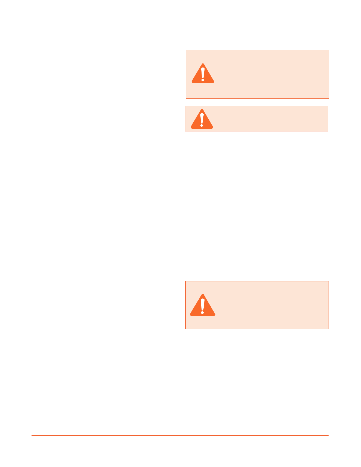
s you read through the procedures, you will come across NOTES, C UTIONS, and W RNINGS.
Each one is there for a specific purpose.
•NOTES give you additional information that will help you to complete the procedure.
•CAUTIONS warn you against making an error that could damage the vehicle.
•WARNINGS remind you to be careful when there is a risk of personal injury.
Below are some basic W RNINGS that you should heed when you work on the vehicle’s
body. They are not all inclusive, however, and common sense must be used when servicing vehicles.

10 Aeromaster on Ford Chassis—Body Wiring Manual
WARNING: Always remove the (Black)
Negative cable irst and connect it last.
WARNING: To avoid accidental shock or
damage to the vehicle, disconnect the
battery be ore servicing an electrical
component. Check your chassis-
supplied operation or service in orma-
tion or speci ic recommendations.
Access
NOTE: The batteries on most Ford
Aeromasters are lo ated under the
hood. (See Illustration BA–5.)
Otherwise see the Chassis Servi e
Manual.
NOTE: Some hoods have a safety
lo king strut. (See Illustration BA–
5.) Do NOT lose the hood without
first pressing the orange button on
the passenger side gas strut to
disengage the safety lo king
me hanism if equipped. Failure to
do so ould result in damage to the
hood.
CAUTION: Do NOT close the hood
without irst pressing the orange button
on the passenger side gas strut to
disengage the sa ety locking mecha-
nism i equipped. Failure to do so could
result in damage to the hood.
BatteryReporting Sa ety De ects
United States Only
If you believe that your vehicle has a defect that
could cause a crash, injury, or death, you should
immediately inform the National Highway Traffic
Safety dministration (NHTS ), in addition to
notifying Utilimaster.
If NHTS receives similar complaints, it may
open an investigation, and if it finds that a safety
defect exists in a group of vehicles, it may order a
recall and remedy campaign. However, NHTS
cannot become involved in individual problems
between you, your dealer, or Utilimaster.
To contact NHTS , you may either call the uto
Safety Hotline toll-free at 800-424-9393 (or 202-
366-0123 in the Washington, D.C., area) or write to:
NHTSA
U.S. Department of Transportation
400 Seventh Street
Washington, DC 20590
You can also obtain other information about motor
vehicle safety from the Hotline.
Canada Only
If you believe that your Canadian-registered
vehicle has a defect that could cause a crash,
injury, or death, you should immediately inform
Transport Canada, in addition to notifying Utili-
master.
To contact Transport Canada, call 800-333-0510 (or
613-993-9851 in the Ottawa region) or write to:
Transport Canada
Motor Vehicle Defect Investigation
PO Box 8880
Ottawa, Ontario, K1G 3J2
NOTE: These wiring diagrams
are a generic sample. Details in
these diagrams may differ from
those in your vehicle. Be ause
Utilimaster manufa tures many
ustomized vehi le bodies, this
manual annot list and illustrate
every possible wiring
onfiguration for every vehi le.
Use this information as a guideline
where it applies.

11Aeromaster on Ford Chassis—Body Wiring Manual
Illustration BA–15
Negative (Bla k) Cable Dis onne ted and Tu ked Away
Illustration BA–10
Plugging in a Memory Saver
Illustration BA–5
Battery Under the Hood and Optional Lo king Strut
Disconnection
1. Make sure the ignition switch is Off.
2. You may need to plug a memory saver
(with 9-volt battery) into the accessory
outlet on the dash. (See Illustration B –
20.) Check your chassis-supplied
operation or service information for
specific recommendations.
3. Disconnect the Negative (Black) battery
cable(s) first. (See Illustration B –25.)
4. Tuck the battery cable away from the
terminal to prevent accidental contact.
5. When servicing the vehicle is finished,
reconnect the cable.
Removal
1. Disconnect battery. (See the
Disconnection Section.)
2. Remove the Positive battery cable(s).
3. Remove the battery hold-downs.
4. Note the location of the posts and remove
the battery from the vehicle.
Installation
1. Install the battery in the battery tray—in
the same orientation.
2. Secure the battery hold-downs.
3. Connect the battery cables, Negative last.
NOTE: Remember to fasten the
hood or a ess panel.

12 Aeromaster on Ford Chassis—Body Wiring Manual
Wiring Diagrams
1—Wire Color Code and Symbol Key
BK - BLACK
GY - GRAY
PK - PINK
RD - RED
18 - 18 GA
16 - 16 GA
14 - 14 GA
12 - 12 GA
Wire_Color_Codes_Sy bols Sheet 1
NOTES:
1) All connectors are shown in the load (wire lead insertion) position.
2) Special custo er options ay not be covered by these diagra s.
WT - WHITE
VT - VIOLET
DG - DARK GREEN
DB - DARK BLUE
BR - BROWN
OR - ORANGE
LG - LIGHT GREEN
LB - LIGHT BLUE
YL - YELLOW
WIRE GAUGE CHART:
WIRE COLOR CODE:
A
C100
A
C101
CAVITY
IDENTIFICATION
CONNECTOR
NUMBER
CONNECTOR
SYMBOL
3) Wire colors on so e optional equip ent ay vary fro this docu ent.
GROUNDED TO BODY
CONTINUED FROM
ANOTHER SHEET
CONTINUE TO
ANOTHER SHEET
CONTINUED WITH NO
NUMBER ASSIGNED
SPLICE
500 BK 14
WIRE GAUGE SIZE
CIRCUIT NUMBER
WIRE COLOR
SYMBOL CODE:
CIRCUIT AND CONNECTOR CODE:
C100
COWL CONNECTOR
12020991
CONNECTOR NUMBER
PART NUMBER
DESCRIPTION

13Aeromaster on Ford Chassis—Body Wiring Manual
Circuit ID - Diagra 58231268A Sheet 7
DARK BLUE W/ WT STRIPE
WIPER PUMP
VIOLET890
WIPER MOTOR PARK
GRAY840
WIPER MOTOR HIGH
RED830
WIPER MOTOR LOW
DARK GREEN820
HVAC WATER VALVE
DARK BLUE731
A/C SIGNAL
DARK GREEN710
HVAC POWER
700
FORWARD LAMP GROUND
BLACK
HVAC GROUND
BLACK530
540
HEADLAMP HIGH BEAM
HEADLAMP LOW BEAM
DESCRIPTIONCOLOR
CIRC
NO.
110 IGNITION POWER
120 ORANGE WIPER POWER
150 RED BATTERY POWER
200 DARK BLUE DOME LIGHT
220 YELLOW CARGO LIGHT
222 CARGO LIGHT 3-WAY
224 CARGO LIGHT 3-WAY
230 BROWN RUNNING/TAILIGHTS
232 DARK GREEN
233 DARK GREEN
234 RED STOP ONLY LIGHTS
235 YELLOW FRONT LEFT TURN
236 LIGHT GREEN BACK UP LIGHTS
237 GRAY
238 YELLOW
240
242
243 RT HEADLAMP HIGH BEAM
280 ILLUMINATION
380 LIGHT BLUE SECURITY CIRCUIT 1
381 VIOLET SECURITY CIRCUIT 2
500 BLACK GROUND
510 WIPER MOTOR GROUND
PINK W/ BLACK STRIPE
YELLOW W/ BLACK STRIPE
RIGHT TURN/STOP
FRONT RIGHT TURN
UNIVERSAL TURN/STOP
LEFT TURN/STOP
LIGHT GRN W/ BK STRIPE
RED W/ BLACK STRIPE
RED W/ WHITE STRIPE
LIGHT BLUE W/ RED STRIPE
YELLOW W/ WHITE STRIPE
241 LIGHT GRN W/ WT STRIPE RT HEADLAMP LOW BEAM
BLACK W/ WHITE STRIPE
2—Circuit Number Identi ication
NOTE: These wiring
diagrams are a
generic sample.
Details in these
diagrams may differ
from those in your
vehicle. Be ause
Utilimaster
manufa tures many
ustomized vehi le
bodies, this manual
annot list and
illustrate every
possible wiring
onfiguration for
every vehi le. Use
this information as a
guideline where it
applies.

14 Aeromaster on Ford Chassis—Body Wiring Manual
3—Connectors
Standard
WIRING DIAGRAM FORD
SHEET 2 OF 58231009b02
1234
5678
AB
CD
EF
GH
7
1
4
2
5
8
3
6
9
ABCDEF
E
B
A
DC
AB
CD
EF
GH
7
1
4
2
5
8
3
9
10
11 12
13
14 15
6
123
456
789
10
11
12
13
14
15
123
456
789
V
UT
S
R
QP
O
N
M
LK
J
HG
F
E
D
CB
A
A
BC
D
E
F
GH
J
KL
M
N
O
PQ
R
S
TU
V
UN TS BU LT AFTER 04/28/98
C200B
FORWARD LAMP FEED
E8EB-14A624-AYA
235 YL
240 LG/BK
233 DG
242 RD/BK
230 BR
8
5
4
1
232 DG
230 BR/WT
238 YL
236 BK/LG
236 LG
700 DB/WT
190 RD
700 DB/WT
350 BK/PK
710 DG
200 DB
130 RD
180 PK
753 YL
753 YL
110 PK/BK
150 RD
A
B
C
D
D
C
B
A
C117
FORD TA LL GHT JUMPER
F2US-14A411-B
(ORANGE CONNECTOR)
C116
NST-3
F2US-14370-A
C115
NST-1
F2US-17B587-B
C114
NST-2
F2US-13A718-A
C118
FORD TA LL GHT CONNECTOR
F2US-14A411-D
(BROWN CONNECTOR)
UN TS BU LT AFTER 03/31/97
UN TS BU LT BEFORE 03/31/97
700 DB/WT
120 OR
830 RD
890 VT
820 DG
840 GY
510 BK/WT
234 RD
280 LB/RD
232 DG
238 YL
230 BR
233 DG
240 LG/BK
235 YL
242 RD/BK
230 BR
130 RD
150 RD
H
G
F
E
D
C
B
A
242 RD/BK
233 DG
240 LG/BK
230 BR
350 BK/PK
500 BK
231 BR/WT
280 LB/RD
110 PK/BK
350 BK/PK
231 BR/WT
232 DG
710 DG
234 RD
280 LB/RD
110 PK/BK
710 DG
510 BK/WT
180 PK
200 DB
510 BK/WT
200 DB
180 PK
238 YL
232 DG
238 YL
230 BR
C200
FORWARD LAMP FEED
12034342
120 OR
C111
POWER FEED #1 CAP
770028-1
C110
POWER FEED #1 PLUG
770021-1
C101
COWL CONNECTOR
12020005
230 BR
235 YL
234 RD
130 RD
150 RD
500 BK
840 GY
830 RD
890 VT
520 BK
820 DG
120 OR
520 BK
820 DG
840 GY
830 RD
890 VT
120 OR
890 VT
710 DG
830 RD
820 DG
840 GY
510 BK/WT
120 OR
234 RD
110 PK/BK
236 LG
238 YL
232 DG
230 BR
258 LB/WT
510 BK/WT
257 LB
840 GY
820 DG
256 DG/WT
830 RD
254 DG
710 DG
890 VT
C113
POWER FEED #2(CAP)
770030-1
C112
POWER FEED #2(PLUG)
770023-1
C200
FORWARD LAMP FEED
12015799
C100
COWL CONNECTOR
12020991

15Aeromaster on Ford Chassis—Body Wiring Manual
Connectors Dia
g
ram 58231009bb03
AB
CD
8
36
7
14
1
2
3
4
1
2
3
4
8
36
7
14
8
36
7
14
AB
C
D
AA
E
B
A
DC
E
B
A
DC
A
B
E
CD
C210
DRL(DAYT ME RUNN NG LAMPS)
12015792
C301
AUX L ARY SW(BATTERY HOT)
999-16716.001
C302
AUX L ARY SW( GN T ON HOT)
999-16716.001
C303
AUX L ARY SW(BATTERY HOT)
999-16716.001
242 RD/BK
233 DG
230 BR
500 BK
240 LG/BK 242 RD/BK 240 LG/BK
500 BK
230 BR
233 GY
C203
RT HEADLAMP D ST
12034342
C202
RT HEADLAMP FEED
12065158
B
A
A
B
222 YL/BK
254 YL
500 BK
256 RD
C205
LT HEADLAMP D ST
12034342
700 DB/WT
710 DG
280 LB/RD
530 BK
700 DB/WT
710 DG
280 LB/RD
530 BK
110 PK/BK
254 DG
256 DG/WT
257 LB
258 LB/WT
280 LB/RD
150 RD
500 BK
280 LB/RD
500 BK
220 YL
150 RD
224 YL/WT
280 LB/RD
500 BK
240 LG/BK
242 RD/BK
710 DG
510 BK/WT
820 DG
120 OR
840 GY
830 RD
890 VT
500 BK
240 LG/BK
242 RD/BK
500 BK
235 GY
230 BR
C330
HVAC CONN.
770019-1
C209
A/C JUMPER
12015791
C207
W PER MOTOR
12015798
C206
WASHER PUMP
480115-1
C208
W PER MOTOR
12015791
230 BR
C204
LT HEADLAMP FEED
12065158
240 LG/BK
242 RD/BK
235 YL
500 BK
D
C
E
BA
C340
AUX. HTR(SCS)
12015024
C331
HVAC CONN.(SCS)
770209-1
87
86 87a 85
30
C310
RELAY
16512282
701 DB/WT
110 PK/BK
700 DB/WT
500 BK
3—Connectors
Standard (continued)

16 Aeromaster on Ford Chassis—Body Wiring Manual
3—Connectors
Standard (continued)
7
1
4
2
5
8
3
9
10
11 12
13
14 15
6
14
25
36
14
25
36
123
456
789
10
11
12
13
14
15
123
456
789
10
11
12
13
14
15
7
1
4
2
5
8
3
9
10
11 12
13
14 15
6
110 PK/BK
C412
"A" P LLAR(P LLAR)
770023-1
C411
"A" P LLAR(P LLAR)
770023-1
C415
"A" P LLAR(ROOF)
.180 FEMALE BULLET
C414
"A" P LLAR(ROOF)
.180 FEMALE BULLET
180 PK/BK
500 BK
234 RD
258 LB/WT
257 LB
150 RD
254 DG 256 DG/WT
350 BK/PK
200 DB
520 BK
231 BR/WT
224 YL/WT
220 YL
222 YL/BK
180 PK/BK
500 BK
234 RD
257 LB
258 LB/WT
256 DG/WT
254 DG
231 BR/WT
224 YL/WT
150 RD
350 BK/PK
520 BK
200 DB
222 YL/BK
C419
NTER OR ROUTED
REAR L GHT NG
770027-1
C418
NTER OR ROUTED
REAR L GHT NG
770020-1
234 RD
234 RD
500 BK 500 BK
230 BR
238 YL
232 DG
236 LG
232 DG
238 YL
230 BR
236 LG
254 DG
231 BR/WT
231 BR/WT
231 BR/WT
200 DB
220 YL
520 BK
222 YL/BK
200 DB
350 BK/PK
256 DG/WT
150 RD
234 RD
500 BK
258 LB/WT
231 BR/WT
224 YL/WT
257 LB
520 BK
220 YL
220 YL
C413
"A" P LLAR(ROOF)
770029-1
C410
"A" P LLAR(DASH)
770029-1
WIRING DIAGRAM FORD
SHEET 4 of 58231009b04

17Aeromaster on Ford Chassis—Body Wiring Manual
3—Connectors
Standard (continued)
A
D
B
E
C
A
E
B
A
DC
A
D
B
E
C
E
B
A
DC
A
A
A
E
B
A
DC
A
D
B
E
C
230 BR/WT
238 YL
232 DG
236 BK/LG
C611
REAR LAMP FEED
12065158
C610
REAR LAMP D ST.
12034342
232 DG
230 BR
238 YL 236 LG
234 RD
C623
L CENCE PLATE LAMP
12010996
C622
L CENCE PLATE LAMP
12010996
230 BR
230 BR
230 BR 230 BR
230 BR
238 GY
500 BK
236 LG
234 RD
234 RD
234 RD
236 LG
230 BR
232 DG
500 BK
232 GY
230 BR
236 LG
500 BK
236 LG
234 RD
230 BR
238 YL
500 BK
C634
LT REAR LAMP D ST
12065158
C632
RT REAR LAMP D ST
12065158
C620
L CENCE PLATE LAMP
12010996
C633
LT REAR LAMP FEED
12034342
C631
RT REAR LAMP FEED
12034342
C621
L CENCE PLATE LAMP
12010996
WIRING DIAGRAM FORD
SHEET 5 of 58231009xx05
C635
RT STOP
282087-1
500 BK
230 BR
237 RD
123
C635
RT BACK-UP LAMP
282087-1
500 BK
236 LG
123
C637
LT STOP
282087-1
500 BK
230 BR
234 RD
123
C635
LT BACK-UP LAMP
282087-1
500 BK
236 LG
123

18 Aeromaster on Ford Chassis—Body Wiring Manual
3—Connectors
Standard (continued)
C
B
A
A
B
C
C
B
A
A
B
C
242 RD/BK
BAAB
240 LG/BK
242 RD/BK
240 LG/BK
230 BR
235 GY
230 BR233 GY
500 BK
500 BK
242 RD/BK
500 BK
240 LG/BK
240 LG/BK
500 BK
242 RD/BK
C711
LT HALOGEN HDLP
12048369
C710
RT HALOGEN HDLP
12048369
C711
LT RECT. NCAD. HDLP
12077384
C710
RT RECT. NCAD. HDLP
12077384
WIRING DIAGRAM FORD
SHEET 6 of 58231009xx06
C715
LT FRONT SDMRKR LAMP
MOLDED CONN.
C714
RT FRONT SDMRKR LAMP
MOLDED CONN.
C712
RT FRONT TURN LAMP
282087-1
500 BK
230 BR
233 GY
123
C641
RT REAR TURN LAMP
282087-1
500 BK
2326 Y
123
C713
LT FRONT TURN LAMP
282087-1
500 BK
230 BR
233 GY
123
C642
LT REAR TURN LAMP
282087-1
500 BK
238 GY
123

19Aeromaster on Ford Chassis—Body Wiring Manual
4—Harness Layout (Connector Locations)
Harness Layout Diagram 58231042A06
C419
C418
C412
C413
C620
C621
CARGO
L GHT
CARGO
L GHT
DOOR
AJAR
CLRC/CHMSL
LT
CLRC
LT
C210
C638
C637
C636
C635
CLRC
LT
CLRC
LT
CLRC
LT
CLRC
LT
CLRC
LT
CLRC
LT
CLRC
LT
CLRC
LT
CLRC
LT
CLRC
LT
V EW-AA
C101
DOME
L GHT
ROOF TO REAR STRUCTURE
CONNECT ON(NO CONN. #'S)
C715
C714
C713
C712
C711
C710
C415
C411
C414
C205
C204
C200
C209
C208
C207
C206
C203
C202
C660
C304 C303
C110
C112
C116
C114
C115
MA N HARNESS
PWR FEED
C113
C111
GROUND
C G
LTR
GROUNDS
V EW-AA
(UNDER DASH)
TO
SCS
W R NG
C331
C330
C410
C302
C301
C100
POWER FEED HARNESS
CHASS S NFC

20 Aeromaster on Ford Chassis—Body Wiring Manual
5—Power Distribution
65 DG
298 VT/OR
297 BK/LG
38 BK/OR
38 BK/OR
FORD IGNITION SWITCH
(TERMINAL "A1")
FORD IGNITION SWITCH
(TERMINAL "A2")
REAR LIGHTING
230 BR
236 LG
TRAILER BATTERY
CHARGE RELAY
REAR LIGHTING
ROUTED THRU
INTERIOR ONLY
230 BR
232 DG
238 YL C101
C101
C101
C101
L
O
M
NN
M
O
L
C100
C100
C100
C100
236 LG
37A YL
37B YL
297 BK/LG
65 DG
37YL
298 VT/OR
37YL
687 GY/YL
49 OR
19 DB/RD
297 BK/LG
FORD HEADLAMP SWITCH
POWER DISTRIBUTION
19 DB/RD
POWER DISTRIBUTION
POWER DISTRIBUTION
POWER DISTRIBUTION
POWER DISTRIBUTION
POWER DISTRIBUTION
REAR LIGHTING
REAR LIGHTING
REAR LIGHTING
POWER DISTRIBUTION
Power Dist - Diagram 58231009 Sheet 8
CHASSIS POWER
DISTRIBUTION BOX CHASSIS FUSE BLOCK
This manual suits for next models
5
Table of contents
Other Utilimaster Truck manuals