AUSA D 201 RH User manual

D 201 RH
D 201 RHS
D 201 RHG
D 201 RHGS
OPERATOR’S
MANUAL
ENGLISH
Original Manual


D 201 RH
D 201 RHS
D 201 RHG
D 201 RHGS
Original Manual
Above chassis number 62439


D201RH / RHS / RHG / RHGS 3
Foreword Thank you for selecting this model of AUSA dumper (hereafter called dumper),
which offers you the best in terms of value for money, safety and operating comfort.
The preservation of these qualities over a long period of time lies in your hands. The
correct use of your dumper will allow you to make the most of its potential.
We recommend you read and study the Operator Manual before using the dumper; this
is to instruct all individuals who may come into contact with the dumper, especially the
operator. The contents of the Manual will help you to get to know your AUSA dumper,
including: everything concerning start-up, driving method, maintenance, preservation,
the uses for which it is designed and the safety instructions that should be kept in mind.
Any damage resulting from the incorrect use of the dumper shall not be deemed to be
the responsibility of AUSA.
In the event of query, complaint or to place an order for spares, please contact your
Official AUSA Agent - Distributor.
For further information, please contact:
AUSA Center, S.L.U.
Apartado P.O.B. 194
08243 MANRESA (Barcelona) SPAIN
Tel. 34 - 93 874 75 52 / 93 874 73 11
Fax 34 - 93 873 61 39 / 93 874 12 11 / 93 874 12 55
E-mail: [email protected]
Web: http://www.ausa.com
AUSA is continually improving its products and reserves the right to make the necessary
modifications, without being obliged to incorporate these modifications into previously
sold products. As such, we will not accept claims that are based on the data, illustrations
or descriptions included in these instructions.
Only original AUSA spare parts should be used. This is the only way to guarantee
that AUSA machinery has the same operational level as at the time of delivery.
No alterations should be made to the dumper without the prior authorization of the
manufacturer.
Keep this Manual in the space on the right hand side of the engine compartment
(fig. 1).
(fig. 1)
MOP 050813 02

D201RH / RHS / RHG / RHGS
4
Table of Contents Dumper use and Inappropriate use........................................................................ 5
Dumper Identification.............................................................................................. 6
Technical Specifications.......................................................................................... 7
Technical data......................................................................................................... 9
Plates and stickers.................................................................................................. 12
Special Safety Messages........................................................................................ 14
Dumper main components Identification................................................................ 20
Instrument Panel ..................................................................................................... 24
Fuel.......................................................................................................................... 27
Dumper Operation.................................................................................................. 29
Special Procedures................................................................................................. 33
Maintenance. General comments........................................................................... 35
General maintenance and lubrication chart............................................................ 36
Liquids and lubricants............................................................................................. 41
Periodic Maintenance Operations........................................................................... 43
Dumper Transport ................................................................................................... 60
Towing the dumper.................................................................................................. 62
Electric Diagram...................................................................................................... 63
Hydraulic Diagrams................................................................................................. 69
EC Certificate of Conformity.................................................................................... 75

D201RH / RHS / RHG / RHGS 5
The D 201 RH, RHS, RHG and RHGS dumpers have been designed and made to
transportloose materials(mortar,concrete, sand,gravel as wellas rubbleand demolition
material) over rough terrain.
Anyuse otherthanthat describedabove shall beconsidered inappropriateand therefore
improper.
Strict adherence to the operating, maintenance and repair conditions specified by the
manufacturer are essential in order to maintain the dumper in good working order.
Driving, maintenance and repair of the dumper should only be carried out by suitably
qualified personnel, with the necessary tools and knowledge of the control and safety
procedures relative to the dumper.
When handling loads or carrying out maintenance and/or repair work, the occupational
health and safety regulations, together with those relative to accident prevention, should
be observed.
When driving with the dumper on public highways, special care should be taken to
ensure compliance with the current legislation for this type of dumper (Highway Code).
AUSA does not accept responsibility for possible damage as a result of any modification
to the dumper made without their express authorization.
Textsmarkedwiththissymbolprovideinformationaboutrecyclingandenvironmental
protection.
Inappropriate use
Inappropriate use is understood to mean the use of the dumper in a manner not in
keeping with the criteria and instructions given in this Manual and in a way which might
cause damage to persons or objects.
Some of the more common and dangerous examples of improper use are given below:
- Carrying persons other than the operator in the bucket.
- Not strictly observing the instructions for use and maintenance given in this
Manual.
- Exceeding load limits.
- Working on unstable, unshored grounds or at the edges of trenches and ditches.
- Working on excessively steep slopes.
- The use of accessories or equipment for purposes other than those for which
they have been designed.
- The use of accessories or equipment not manufactured or authorized by AUSA.
Dumper use and
Inappropriate use

D201RH / RHS / RHG / RHGS
6
Important! When contacting AUSA or their dealers with respect to your dumper,
you should give the following details: Model, date of purchase, chassis number and
engine number. This data is shown on the identification plate.
For ease of access, write this information in the spaces given below:
Dumper model:....................................................................
Date of purchase:.................................................................
Chassis number:..................................................................
Engine number:....................................................................
Machine identification plate: (fig. 1) This is located on the left-hand side
engine cover under the driver’s seat. It includes the EC mark.
Chassis number: (fig. 2) This is engraved on the right-hand front cross of the
chassis.
Chassis number: (fig. 3, 4) This is engraved on the right-hand side of the
engine, below the exhaust manifold and is also given on a label on the rocker arm cover.
Identification plates for the main components: The identification plates
corresponding to all those components not directly constructed by AUSA (for example:
engines, pumps, etc.) are located on the components themselves, in the positions in
which the respective manufacturers originally placed them. For further information see
the section IDENTIFICATIONS PLATES AND LABELS.
Dumper
Identification
(fig. 3)(fig. 4) (fig. 1)(fig. 2)

D201RH / RHS / RHG / RHGS 7
Dimensions chart (in)
D 201 RH / S D 201 RHG / S
A5ft 13in 5ft 05in
B4ft 74in 4ft 74in
C5ft 22in / 5ft 74in 5ft 22in / 5ft 74in
D0ft 61in 0ft 61in
E3ft 92in 3ft 92in
F8ft 46in 8ft 46in
G0ft 84in 84in
H2ft 9 in 3ft 03in
I5ft 38in 5ft 38in
J2ft 35in 2ft 35in
K9ft 91in 9ft 91in
L7ft 37in 8ft 74in
M9in 1ft 76in
N1ft 87in 3ft
R- / 6ft 84in - / 6ft 84in
S- / 13ft - / 13ft
T5ft 22in 5ft 22in
U- 71in
S: Dumper equipped with self-loading shovel
V. maximum visibility with the shovel fully retracted (patented system)
Technical
Specifications

D201RH / RHS / RHG / RHGS
8
Dimensions chart (mm)
D 201 RH / S D 201 RHG / S
A1565 1540
B1445 1445
C1590 / 1750 1590 / 1750
D185 185
E1195 1195
F2580 2580
G255 255
H885 925
I1640 1640
J715 715
K3020 3020
L2245 2665
M275 535
N570 930
R- / 2085 - / 2045
S- / 3980 - / 3980
T1590 1590
U- 215
S: Dumper equipped with self-loading shovel
V. maximum visibility with the shovel fully retracted (patented system)
Technical
Specifications

D201RH / RHS / RHG / RHGS 9
Diesel engine (See the engine instructions manual)
Kubota V1505
Power: 30,8 HP / 22.7 kW at 2600 rpm (according to SAE J 1995 Norm).
Four cylinder, four stroke, water cooled. Mixed water / oil radiator. Electric starter.
Transmission
Hydrostatic system with variable flow.
Permanent 4x4 transmission with COMPEN. system®.
Two-speed hydrostatic motor, electrically controlled
FNR selector
The drive selection (forwards/ backwards) is made using a switch on the lower part of
the joystick. An indicator lamp in the form of an arrow lights up on the top of the joystick
when a movement mode is selected.
Steering
“ORBITROL” hydraulic system. Drive is in the rear axle, through a double-act cylinder.
Minimum external turning radius
D 201 RH, RHS, RHG, RHGS: 4190 mm./ 13 ft 8,96 in.
Maximum speed
20 Km/h / 12 mph
Gradient negotiable
1st gear: 42 % (with full load).
Brakes
Brakes: On front axle, mechanical action. Multidisc, oil bathed.
Park brake: Cable operation applied to multiple discs on the front axle.
Wheels
Dimensions
Model Front wheels Rear wheels
D 201 RH
10.0/75-15.3” (10PR) 10.0/75-15.3” (10PR)
D 201 RHS
D 201 RHG
D 201 RHGS
Pressures
Model Front wheels Rear wheels
D 201 RH
4 bar
58 PSI 3,5 bar
51 PSI
D 201 RHS
D 201 RHG
D 201 RHGS
Operating temperature
-15 ºC to 40 ºC / 5 ºF to 104 ºF
Technical data

D201RH / RHS / RHG / RHGS
10
Vibration and sound levels
Sound power level
Warrantee sound power (according to 2000/14/EC sound emissions in the environment
by machinery for outdoor use):
• Lwa = 101 dB(A)
Sound pressure level on the operator’s site
A weighted sound pressure in the operator’s ear measured (following norms ISO 6394):
• Lpa = 85 dB(A)
• Measurement uncertainty: 2,5 dB(A)
Vibration level produced by the machine
Root-mean-square frequency-weighted, hand-arm vibration acceleration value:
< 2,5 m//s2
Root-mean-square frequency-weighted, whole body vibration acceleration value:
< 0,5 m/s2
Hydraulic circuit
Operated by a 8 cc. / 0,002 US gal. gear pump connected to the hydrostatic pump; the
pump is used by both the operations and steering circuits.
Two-spools monoblock control valve and solenoid selector for the self-loading shovel
movements (models RHS and RHGS).
Restrictor valve for controlling lowering speed of the bucket when loaded.
Operating pressure:
Hydraulic circuit: 320 bar / 4641,2 PSI.
Control valve: 190 bar / 2755,17 PSI.
Steering: 80 bar / 1160,3 PSI.
Hydraulic oil tank capacity: 40 l. / 8,79 US Gal.
Electric equipment.
Starter: Glow plugs, 1.2 kW starter motor.
Alternator: 12 V/360 W with incorporated regulator.
Battery: 12 V / 70 Ah.
Rotatingbeacon,horn,reverseback-upalarm,warningsignalfor:lowengineoilpressure
and coolant overheating.
Weights
Unladen weight:
D 201 RH: 1600 Kg. / 3527,39 lbs.
D 201 RHS: 1800 Kg. / 3968,32 lbs.
D 201 RHG: 1850 Kg / 4078,55 lbs.
D 201 RHGS: 2050 Kg. / 4519,47 lbs.
Fully laden weight:
D 201 RH: 3600 Kg. / 7936,64 lbs.
D 201 RHS: 3800 Kg. / 8377,56 lbs.
D 201 RHG: 3850 Kg. / 8487,79 lbs.
D 201 RHGS: 4050 Kg. / 8928,72 lbs.
Load capacity
D 201 RH, RHS, RHG, RHGS: 2000Kg / 4409,24 lbs.
Technical data

D201RH / RHS / RHG / RHGS 11
Technical data Bucket
Bucket capacities
D 201 RH, RHS D 201 RHG, RHGS
Water 700 l. / 184,92 US Gal. 650 l. / 171,71 US Gal.
Levelled 960 l. / 253,60 US Gal. 930 l. / 245,68 US Gal.
Heaped 1250 l. / 330,21 US Gal. 1230 l. / 324,93 US Gal.
Control panel and controls
The controls, switches and indicators lamps are incorporated into the joystick and
instrument panel.
Lighting ()
Working lights, parking lights, indicators and hazard lights equipment.
ROPS Protection arch
Built in accordance with ISO 3471 Standards.
Optional equipment ()
Optional equipment is marked with an asterisk (). Optional equipment is only supplied
at the express wish of the customer, for certain versions of the dumper or even only in
certain countries:
- Shovel teeth.
- Homologated lighting equipment
- FOPS/ROPS protective roof with seatbelt, rotating beacon and rear-view mirror)
- Passenger’s seat.
- Grass tires
- Closed cabin with front windshield and wiper
- Towing hitch
- Backhoe loader (only available in RHG / RHGS models)
When the dumper comes equipped with accessories fitted by the factory, please read
the relevant Instruction Manual for each accessory carefully before use. Each accessory
has its own Instruction Manual issued by the manufacturer, and this is provided with the
dumper main Operator’s Manual.
Whereaccessories and equipment are fitted on thebasic dumper chassis by companies
other than the manufacturer, the instructions and limitations of the dumper with respect
to weights and sizes, the effectiveness and settings of the lighting system and the need
for guards on additional systems should be observed to guarantee the dumper safety.

D201RH / RHS / RHG / RHGS
12
Plates and stickers
1 43.00396.01 2 17.12011.00 3 17.12012.00 4 17.12013.00 5 17.12014.00
6 43.01170.02 7 02.00766.01 8 09.15720.00 9 17.12001.00 10 17.12002.00
11 17.12003.00 12 17.12004.00 13 01.01355.08 14 45.19101.00 15 01.00779.26
1- Axle lubrication specifications
2- Main functions of the joystick model RH
3- Main functions of the joystick model RHS
4- Main functions of the joystick model RHG
5- Main functions of the joystick model RHGS
6- Engine lubrication
7- Warning sign for engine cooling fan
8- Lifting point
9- Identification of the model RH
10- Identification of the model RHS
11- Identification of the model RHG
12- Identification of the model RHGS
13- Tire pressures
14- Certification
15- Specifications plate

D201RH / RHS / RHG / RHGS 13
16 43.00395.01 17 13.12136.00 18 01.01355.05 19 17.12015.00 20 17.12015.00
21 02.00777.00 22 12.12010.00 23 01.00757.00 24 02.00773.03 25 02.00773.03
26 09.00769.00 27 14.00775.03 28 09.12011.00 29 17.12010.00
Plates and stickers
When leaving this vehicle
unattended macke sure the
shovel is lowered to the
ground!
02.00775.03
16- COMPEN system
17- Constructor identification
18- Pressure indication for the Tires
19- Reminder that it is prohibited to carry passengers
in a dumper without a specific seat
20- Warning against using high pressure washing
21- Authorized use of the machine
22- Sign warning that use of seatbelt is obligatory
23- The use of protective earmuffs is obligatory
24- Warning sign indicating that the bucket must be
lowered before leaving the dumper
25- Warning sign indicating that the shovel must be
lowered before leaving the dumper
26- Cautious driving reminder for the dumper
27- Danger warning in the machine operating area
28- Noise level emissions
29- Lifting point
D201RH / RHS / RHG / RHGS
14
Special
Safety
Messages
(fig. 1)(fig. 2)
General comments
AUSA manufactures its dumpers in accordance with the intrinsic protection
requirements, as established by current legislation in the countries of the European
Economic Community, regarding the dangers of any nature which may put health or
life at risk, whenever the machinery is in use and maintained in accordance with these
guidelines. Any danger resulting from improper use, not complying with these provisions
or others which are specifically provided with the machinery, shall be the responsibility of
the user and not of AUSA.
This section provides instructions on the use of the dumper, in accordance with that
established by the Directive for Safety of Machinery 2006/42/EC.
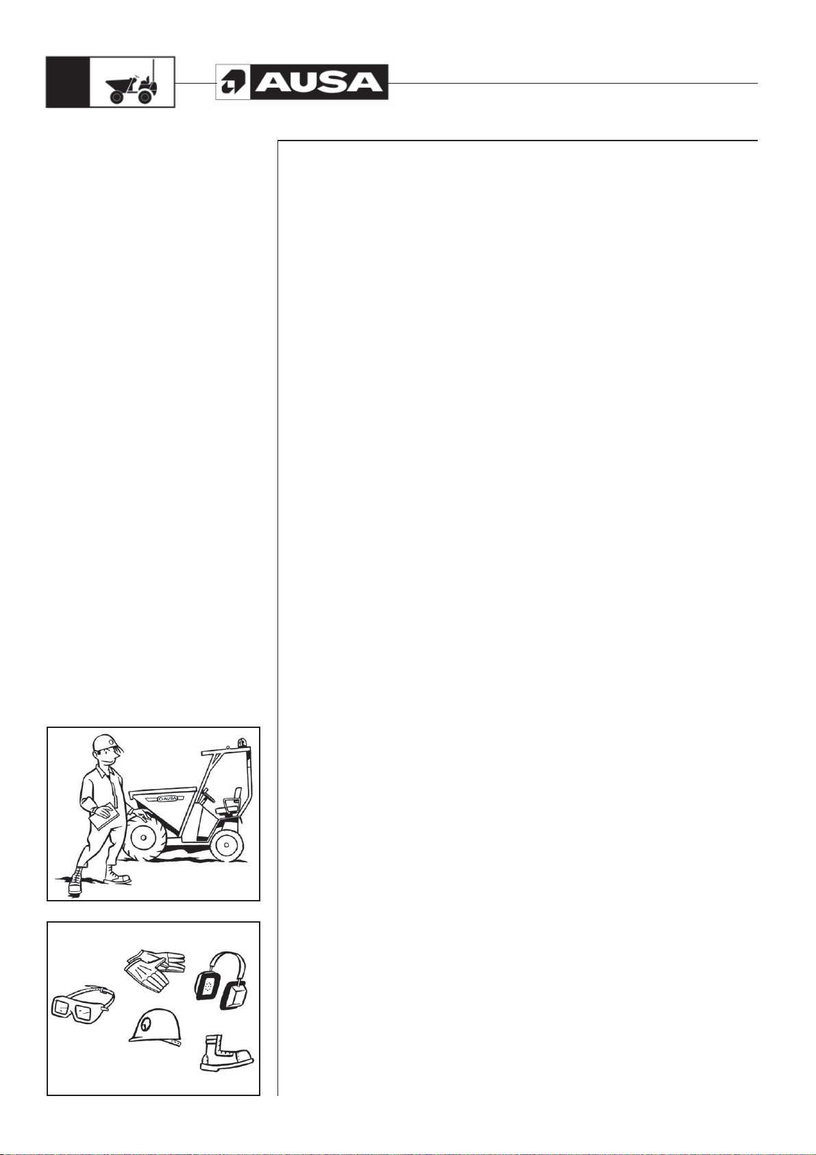
Before using the dumper which is initially unfamiliar, you should read the Manual closely
and resolve any doubts with a supervisor (fig. 1).
The dumper must only be used by authorized and correctly trained personnel.
Operator clothing
Request the personal protective equipment required to carry out the work in safety, for
example: helmet, protective earmuffs, outwears clothing, reflective equipment, safety
goggles, etc. (fig. 2).
The wearing of bracelets, chains, loose ropes, long hair which is not tied up, etc., is
not recommended due to the risk of catching these in controls, rotating components,
edges, etc.
Dumper description
A dumper is an engine-driven dumper used to carry loads with the help of special
attachments designed for the intended work (bucket and, depending on the version,
self-loading shovel). The dumper can tip the bucket in order to unload it. It consists of a
resistant chassis resting upon two axles. The front axle is the drive axle and the rear axle
the steering axle, although versions exist in which both axles are drive axles.
The front of the dumper is equipped with the bucket and, depending on the version, the
self-loading shovel. The unit formed by both is designed to lift and tilt the load forwards
and backwards, making handling easier.
Rudiments of static equilibrium
Sothatthedumperisabletohandleloadsinastableandsafemanner,certainequilibrium
conditions must exist and be maintained between the load and the machinery. For
this reason the dumper has been fitted with counterweights. These are designed to
compensate for the weight of the load being carried, as long as the centre of gravity
of the load and the dumper are within certain established limits. See the DUMPER
IDENTIFICATION PLATE in order to verify the load capacity and the load centre of gravity
permitted.
Rudiments of dynamic equilibrium
While the dumper is moving, and as it gains speed, the equilibrium conditions of the
load-dumper unit are modified as the centre of gravity shifts. This is accentuated on
lifting loads, turning, braking, etc. Under these conditions, a maximum of concentration
is required so that the centre of gravity of the load is kept within the established limits.
Dumper equilibrium
The dumper counterweight counter acts imbalance of the weight even when unloading.
The centre of gravity is maintained low and close to the rear of the dumper. When the
load is collected, the imbalance is corrected and the centre of gravity shifts forward. If
the load is within the correct limits then the correct equilibrium is maintained. As the load
is lifted, the centre of gravity also rises, shifting upwards. At the moment that the centre
of gravity shifts beyond the dumper, the equilibrium is lost and the dumper becomes
unstable. Therefore, the dumper should not move while the bucket is raised.

D201RH / RHS / RHG / RHGS 15
Special
Safety
Messages
(fig. 1)(fig. 2)(fig. 3)
Stability
Do not carry unstable or loose loads, or loads which are oversized with respect to the
dumper (fig. 1).
When the bucket is being lifted, ensure that the dumper is on stable ground and that it
is as flat as possible.
Do not drive over objects which may endanger the stability of the machine.
The triangle of horizontal stability
To prevent the loads which are being transported from falling, it is necessary to consider
the triangle of horizontal stability (fig. 2). This is an imaginary inverted triangle, with the
lower end located on the centre of the rear axle and the two upper vertices on each of
the front wheels. Stability is guaranteed when the centre of gravity of load (C) and the
machine (M) always remain within an imaginary line, starting from the lower vertex of the
triangle to the centre of the base of the same, located between the front wheels.
Longitudinal stabilization
Thedumpermustnotbe drivenwiththebucketraised. Theriskoflongitudinaloverturning
increases if the dumper is driven while the load is raised. Sharp braking and accelerating
or rapid tilting movements decrease stability.
Transversal stability
The risk of overturning sideways increases on turning at unsuitable speeds, while
the dumper is unladen or when the load is raised. Rough ground, sharp braking or
accelerating or shifts in the load make these conditions worse.
The centre of gravity and the dumper capacity
Do not overload the dumper or handle loads which shift the centre of gravity beyond
that for which it is designed. Manoeuvre slowly, especially when changing direction on
slippery ground.
The load and counterweight
The raised load should only be tilted forwards when it is about to be unloaded.
Tilting the load forwards or backwards (swinging) is very useful for collecting or
positioning the load, but affects the longitudinal and lateral stability.
If using an accessory or attachment first check the permitted load. The combination of
the weight of the dumper plus the weight of the accessory reduces the nominal load.
Maximum speed
The speed of the dumper influences its stability. When turning, braking, or accelerating,
the centre of gravity shifts within the triangle of stability. Sharp turns, sudden braking or
acceleratingcause thecentre of gravityto shiftsharply andit may falloutside thetriangle.
This is the moment when the stability of the dumper and the load are not guaranteed and
there is a risk of accident.
When manoeuvring reduce the speed of the dumper and avoid turning the steering
wheel sharply.
The surrounding area
Give your full attention to the task in hand. The safety of the driver and others depends
upon the care taken by the driver (fig. 3).

D201RH / RHS / RHG / RHGS
16
Special
Safety
Messages
(fig. 1)(fig. 2)(fig. 3)(fig. 4)
Pedestrians in the surrounding area
It is forbidden to carry persons on the dumper (fig. 1).
No-one is permitted to remain or cross below the bucket when this is raised, laden or
unladen.
Give way to the right to pedestrians found in your path.
Access and doors
Make sure that the passages and doors along the route are sufficiently high to allow the
entire dumper to pass.
When carrying out lifting and dumping manoeuvres, pay special attention to the height
of the roof, lighting and other overhead installations.
Ground surface
Check that the ground is strong enough to bear the dumper when loaded, especially
when approaching bridges, the edges of embankments, concrete flooring, elevators,
etc. (fig. 2).
Lighting
The dumper working area should be adequately lit to prevent the risk of accidentally
running over persons or colliding with obstacles. As soon as the daylight fades, the
dumper lighting system should be switched on. If the dumper is not equipped with
lighting, make sure that the working area is adequately lit. If this is not possible, do not
continue working with the dumper, this may result in an accident.
The loading bay. Communication. Shelving and installations.
The load
The loading bay or area where the loads are handled should be correctly equipped
and signposted. The operating area of the dumper should be free of obstacles and
pedestrians, however if their presence is necessary, the pedestrians should move in
areas which have been duly marked as such and they should be easily distinguished,
for example, by wearing reflective jackets.
If the area is closed it should be well-ventilated and the dumper must be equipped with
lighting and exhaust gas purifier systems.
The dumper operator should be able to communicate normally with pedestrians. If
the surrounding area is excessively noisy, pedestrians should refrain from walking in
the immediate vicinity. If this is unavoidable, the utmost care should be taken. Radio
communication equipment should not be handled while driving the dumper. If it is
necessary to use the radio, pull over to one side and signal the position of the dumper,
using the lights or hazard warning lights.
Before handling a load using the dumper, check the load and ensure that its weight does
not exceed its capacity. At the same time, check that the load is stabilized and correctly
secured, to ensure that no part of the load falls off during transportation.
Do not dump the bucket contents over a bank or slope without ensuring stability and
until there is a rail that will act as a stop for the wheels. A plank on the ground cannot be
considered as an acceptable safety stop (fig. 3).
When the dumper is loaded using a shovel, crane or other similar external method, the
driver should not remain in the driver’s cab (fig. 4).
Dump the load progressively paying careful attention to the dumper stability. Avoid
transporting material that may stick or jam in the bucket, such as clay type mud, large
stones or rubble; the dumper may become unstable during unloading and cause an
accident.

D201RH / RHS / RHG / RHGS 17
Special
Safety
Messages
(fig. 1)
Order and cleanliness
Carrying out a series of checks before starting the dumper and keeping the operator cab
clean help to make the work safer.
To do so, follow the GENERAL MAINTENANCE AND LUBRICATION CHART given
in this Manual strictly, and keep the operator position clean and free of earth, gravel,
mud, oil or other objects which may cause falls.
Do not carry objects in the operator cab. These may injure the operator or accidentally
activate the dumper controls (fig. 1).

D201RH / RHS / RHG / RHGS
18
Special
Safety
Messages
(fig. 1)
General comments about driving the dumper
Dumper starting basics
Fill up the tank with fuel while the engine is switched off and do not smoke while doing
so. Follow the instructions given in the section Fuel.
Do not start the dumper, or activate the controls if you are not seated in the operator
position.
Adjust the seat to your build.
Keep the driver’s cab free of objects and tools. These may move around, block a control
or a pedal, and prevent a manoeuvre or stop the dumper (fig. 1) previous page.
Before starting to work with the dumper, clean any oil or fuel spills, clean and remove
grease from hands and the soles of shoes. Do not forget to carry out the operations and
daily checks listed in the GENERAL MAINTENANCE AND LUBRICATION CHART.
Check the correct position and fastening of all the guards, caps and safety stops.
Check that all the controls are operating correctly.
Check that informative and safety plates on the dumper are clean and in good condition.
If they are not in good condition, replace the plates.
Check that lighting and signalling components are clean and work correctly. If they do
not work check the corresponding fuses and bulbs as shown in the section PERIODIC
MAINTENANCE OPERATIONS.
Work circuit
The movement of loads within an installation or enclosure must be carried out following
certain instructions concerning the circulation of dumpers and pedestrians. If you are not
aware of these regulations, please check with your supervisor. Study the movements of
the dumper to avoid making manoeuvres which are unnecessary, or involve risk to the
surrounding areas. Find out which paths are suited to the type of dumper you are driving
and the load carried. If it is necessary to drive along public roads, first check that the
dumper complies with current regulations of the country.
Work cycle
If it is necessary to move loads continuously and repeatedly, try to do so with the
minimum number of movements necessary, where possible. Reducing the number of
movements saves fuel and reduces the emission of exhaust gases.
If the work is very intense, remember to check the instrument panel from time to
time, especially in extreme climates, as the engine will be working in particularly hard
conditions.
Driving with the dumper
When approaching a junction with poor visibility, reduce speed, emit acoustic warnings
and proceed slowly according to the available visibility.
Thedumper speedmust alwaysbe adaptedto workingconditions andarea ofoperation.
Systematically driving at the maximum speed permitted by the machine may put the
operator and the surrounding area at risk.
Driving in reverse
Ensure good visibility of the path to be taken. If the load being carried obstructs visibility,
reverse with the utmost of caution.
Beforereversing,theoperatorshouldensuretherearenorisksforthedumper,individuals
or objects in the surrounding area (fig. 1).
This manual suits for next models
3
Table of contents
Other AUSA Truck manuals


 Operator's manual")


