moyes LITESPORT 4 User manual

Mo
y
es Delta Gliders Pt
y
. Ltd. Version 1.01
LITESPOR
T
owners
manua
l


LITESPORT OWNERS MANUAL
Version 1.01 1
CONTENTS
Amendments.........................................................................................2
Introduction...........................................................................................3
Description of Design............................................................................4
Specifications........................................................................................5
Operating Limitations............................................................................6
Disclaimer.............................................................................................7
Assembly Procedures...........................................................................8
Pre-Flight Check.................................................................................16
De-Rigging the Litesport.....................................................................18
Flying The Moyes Litesport.................................................................22
Tuning Hints........................................................................................26
Glider Care.........................................................................................30
Maintenance Schedule.......................................................................32
Sail Removal.......................................................................................33
Checking The Litesport Stability System............................................34
AN Bolt Index.................................................................................35
Purchase Record................................................................................36
Maintenance Log................................................................................36

LITESPORT OWNERS MANUAL
2 Version 1.01
AMENDMENTS
Version Date Changes
1.00 20/08/2003 Created original owners manual.
1.01 5/05/2004 •Added Zoom Upright Assembly Drawing
•Updated Stability System instructions

LITESPORT OWNERS MANUAL
Version 1.01 3
Moyes Delta Gliders Pty. Ltd.
1144 Botan
y
Road, Botan
y
NSW 2019 Australia T: +61
(
0
)
2 9316-4644 F: +61
(
0
)
2 9316-8488 E: mo
y
es
@
mo
y
es.com.au
INTRODUCTION
Thank you for choosing the Moyes Litesport. You have chosen wisely. The
Litesport incorporates the latest hang gliding design innovations to bring
Moyes into the future. The Litesport bridges the gap between intermediate
and topless gliders, providing a very capable glider for either the advancing
pilot, or the an advanced recreational pilot.
Since 1967, Moyes Delta Gliders has strived to be on the cutting edge of
developing hang gliders of the highest calibre. A family owned business
operating under homespun values, we aim to provide a comprehensive
international network to service all pilots. Even further, we work with some of
the best pilots in the world to ensure that our gliders are stringently made and
tested in order to improve their performance, handling, and safety.
We wish you the very best flying,
The Moyes Team

LITESPORT OWNERS MANUAL
4 Version 1.01
DESCRIPTION OF DESIGN
Designed by elite competition pilots, the Moyes Litesport is intended for competition and
enjoyable high performance cross country flying. The Litesport utilises a planform similar
to the Litespeed.
The Litesport features a 7075T6 aluminium airframe, which allows a considerable weight
saving over more conventional alloys. The leading edge uses a step down taper design
with revised sleeving and tube diameters. This produces a lighter outer leading edge
with an improved flex distribution. The low roll inertia provides pleasant handling.
The elliptical fibreglass wing tip has been a feature of Moyes high performance gliders
since the early 80’s. The fibreglass tip creates better turn coordination compared to
conventional designs. With the VG fully engaged, the fibreglass tip produces a tighter
mainsail and more desirable washout distribution.
The pitch stability system utilises a cable braced outer aluminium sprog, providing
support for battens 8 and 9 via a transversal batten. This system was designed with
maximum strength and stiffness in mind, and demonstrates excellent structural integrity
under any flight load. In addition, the kingpost incorporates the G-string compensation
system, which lowers the rear of the sail when the VG is engaged. This allows the luff
line to adjust to the decrease in washout produced by the VG system.
The Litesport sail has a total of 8 internal cloth ribs. These ribs prevent the under
surface from ‘blowing down’, which makes pilot induced oscillations less likely. These
internal ribs are shaped to produce the desired under surface camber for low drag at
high speeds.

LITESPORT OWNERS MANUAL
Version 1.01 5
SPECIFICATIONS
Model Size Litesport 4 Litesport 5
Area 13.8sq m
149 sq ft 14.9 sp.m
160 sp ft
Span 9.6 m
31.5 ft 10 m
32.8 ft
Nose Angle 127 - 129 degrees 127 – 129 degrees
Aspect Ratio 6.7 6.7
Glider Weight 31.8 kg
70 lb 32.5 kg
72 lbs
Optimal Pilot
Weight 75 kg
165 lb 90 kg
198 lb
Hook-In-Weight 68-109 kg
150-240 lb 79-129 kg
175-285 lb
Packed-Length 4950 mm
16.2 ft 5150 mm
16.9 ft
Short-Packed
Length 4330mm
14.2 ft 4500 mm
14.8 ft
C of G
(Front of Keel) 1390 mm
54.7 inches 1430 mm
56.3 inches
Number of
Battens:
Mainsail
Undersurface
21
6
21
6
VNE 85kph
53mph 85kph
53mph
VA 74kph
46mph 74kph
46mph
Trim Speed 34kph
21mph 34kph
21mph
Stall Speed 26kph
16mph 24kph
15mph
Max Speed 97kph
60mph 97kph
60mph
Best Glide Speed 40kph
25mph 47kph
29mph
Best Glide Angle 14:1 14:1
Glide Angle 10:1 58kph
36mph
58kph
36mph

LITESPORT OWNERS MANUAL
6 Version 1.01
OPERATING LIMITATIONS
Your Moyes Litesport is a sophisticated high performance hang glider. If maintained
correctly it will give you years of safe enjoyable soaring. However, it is important that you
display a healthy respect for all aspects of aviation and that you understand the
increased risks of flying in dangerous conditions or in a manner that exceeds the glider’s
operating limitations.
•Flight operation should be limited to non-aerobatic manoeuvres where the glider’s
attitude does not exceed 30 degrees above or below the horizon and bank angles
do not exceed 60 degrees.
•The Moyes Litesport has been designed for foot launched soaring flight and should
not be flown by more than one person at a time. It should not be flown backwards or
inverted.
•The recommended minimum pilot skill level is Intermediate.
•The Moyes Litesport can be flown with auxiliary power when fitted according to the
recommendations of the manufacturer. The user assumes all liabilities.
•The Moyes Litesport should not be flown in excess of the placarded VNE or VA.
•VNE (speed never to exceed): 53mph / 85kph
•VA (maximum rough air manoeuvring speed): 46mph / 74kph
•Stall speed with maximum pilot weight: Less than 25mph / 40kph
•Maximum speed with minimum pilot weight: Less than 50mph / 80kph
The Moyes Litesport will resist spinning and will recover quickly if control forces are
relaxed. Recovery from a stalled turn can be achieved with little height loss and without
much attitude change if the control bar is brought back to a normal flying position. This
will allow the glider to return to normal flight within half a turn.
The Moyes Litesport has been tested to the following:
•Maximum lift angle of attack at a speed of 65mph/105kph
•Negative 30 degrees angle of attack at a speed of 46mph/74kph
•Negative 150 degrees angle of attack at a speed of 32mph/54kph
•Pitch moment tests at 20/32, 37/59 and 54/87 (mph/kph)
These tests confirmed the glider’s structural integrity and positive pitch stability
throughout a broad range of angles of attack.
The Moyes Litesport is capable of flying at speeds greater than the VA and VNE. We
recommend the use of an accurate airspeed indicator to become familiar with control bar
positions at these speeds and normal flying speeds.

LITESPORT OWNERS MANUAL
Version 1.01 7
DISCLAIMER
The owner and operator must understand that due to the inherent risk involved in flying
such a unique vehicle, no warranty is made or implied, of any kind, against accidents,
bodily injury, or death. Operations such as aerobatic manoeuvres or erratic pilot
technique may produce equipment failure.
This glider is not covered by product liability insurance, neither has it been designed,
manufactured, or tested, to any state or federal government airworthiness standard or
regulation.
LITESPORT OWNERS MANUAL
8 Version 1.01
GETTING STARTED
Your new Moyes Litesport may have been shipped to you in the 4.5m breakdown form.
If so, you can assemble your glider to its full length by following these assembly
procedures. All references to ‘top’, ‘bottom’, ‘left’, and ‘right’ refer to the glider and pilot
in flying mode.
Please check your packing list.
•Glider
•2 x back section leading edges: note that the back sections are labelled left and
right.
•1 x batten set: red = left/ green = right/ blue = undersurface
•1 x speed bar
•2 x tip bags
•4 x padding pieces: A-frame top & bottom, keel sleeve, king post top
•1 x Snack Pack with owners’ manual, batten pattern, and promotional wear.
Assembly from 4.5m Breakdown Form
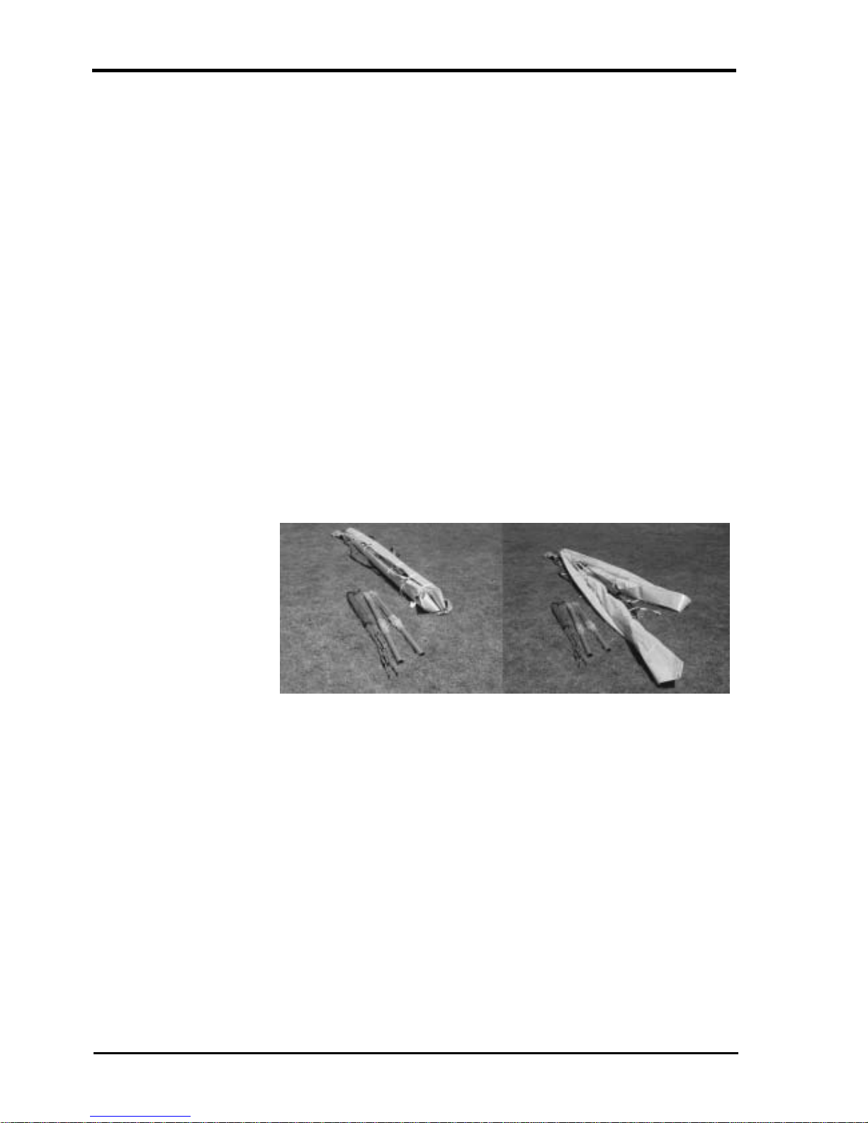
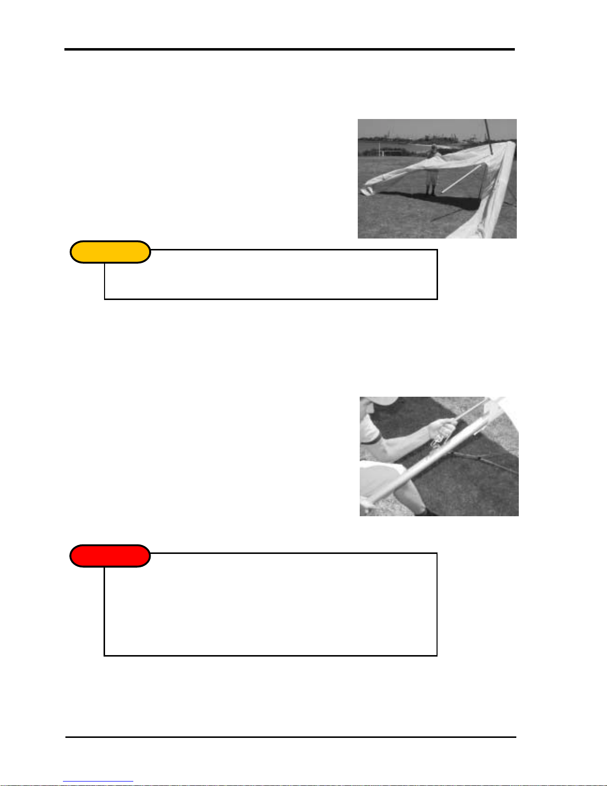
1. Open the glider bag and roll the glider onto its undersurface. Undo the straps and
extend the sail.
Picture 1
Lay the glider on
its undersurface
and unfold the sail.
2. Expose the leading edge/cross bar junction through the inspection zipper. Remove
the bubble wrap and tape from the leading edge/cross bar junction and the end of
the middle sleeve.
LITESPORT OWNERS MANUAL
Version 1.01 9
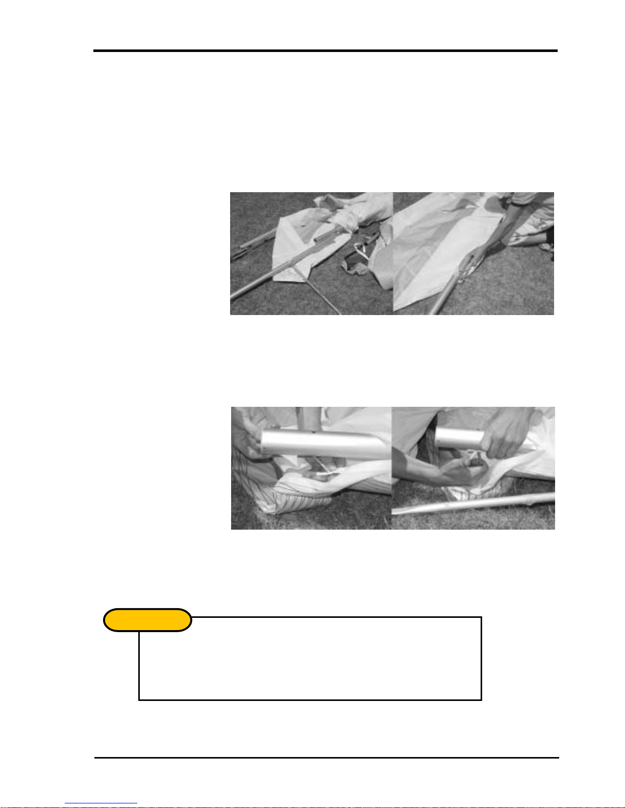
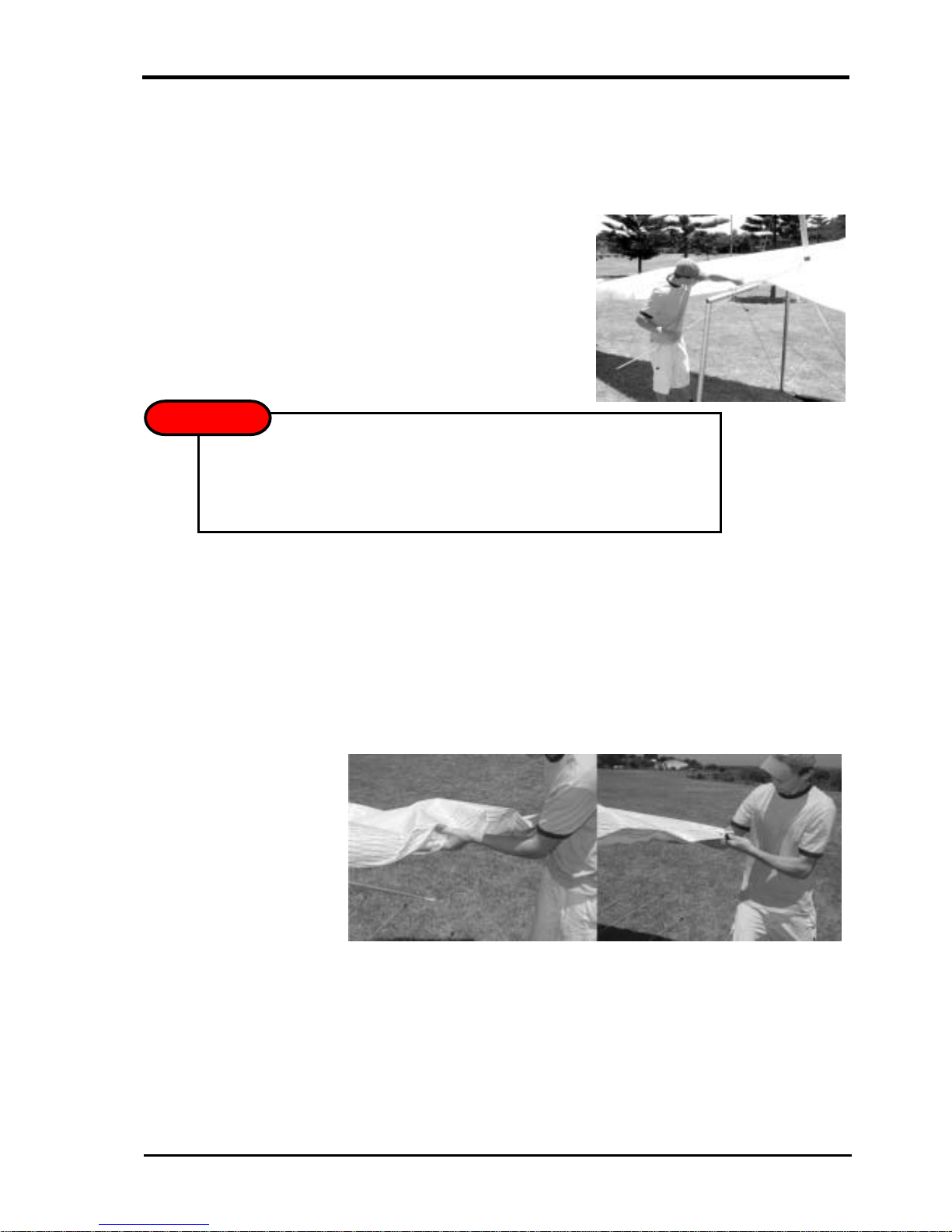
3. Insert the right back section of the leading edge. The left and right back sections
differ from each other in the mounting of the outer sprog. You can check this by
picturing that the cable must be on the top of the leading edge and the sprog must
fold outwards. Push the back section into the mid sleeve while depressing the push
button pin. Continue to slide the back section in until it reaches its stop, then rotate
the back section until the mid sleeve location holes align with the push button pin.
Closely check that the push button pin has fully released and that the back section
cannot be rotated.
Picture 2
Insert the back
ends of the leading
edge.
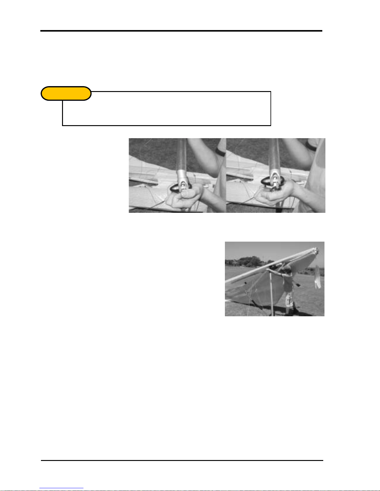
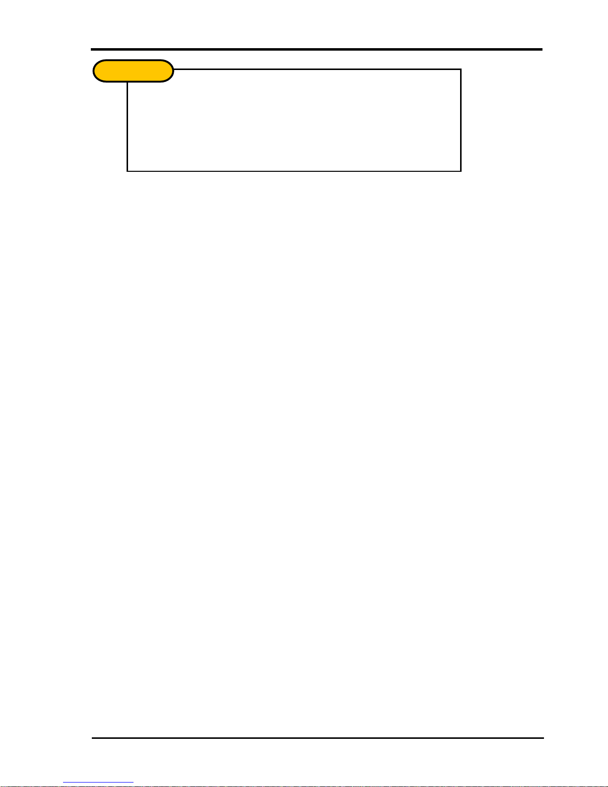
4. Secure the sail by attaching the tip webbing to the end of the leading edge, using
the clevis pin and safety ring supplied. Insert the pin through the webbing and into
the bottom hole at an angle. Straighten the clevis pin while sliding the webbing
towards the leading edge as shown in Picture 3. Ensure the tip webbing is not
twisted and is on the bottom of the leading edge.
Picture 3
Insert the sail pin
Into the end of the
leading edge.
5. Repeat 1-4 to install the left back section. Your Litesport will now be ready for
standard assembly. Before each flight, carefully inspect all tubing, nuts, and bolts, to
ensure no damage has occurred during transportation.
The outer sprog must exit the sail from the long cord wise zipper. The zipper
must be opened when the glider is in standard break down form with the
sprog folding towards the wing tip.
IMP
O
RTANT
!
LITESPORT OWNERS MANUAL
10 Version 1.01
With standard uprights, the uprights will naturally toe-in as shown in Picture 4.
Hold the base bar and the upright, twisting the upright so the connection lines up.
ASSEMBLY PROCEDURES
1. Place the glider on the ground, zipper facing up. Open the bag, undo the ties, and
remove the A-frame bottom padding and battens.
2. Assembly the A-Frame.
Picture 4
Standard uprights
and basebar
assembly.
3. Roll the glider over so that it is standing on the control frame.
Picture 5
Standard uprights
and basebar
assembly.
4. Remove the glider bag and any remaining ties and padding.
N
O
TE
!
LITESPORT OWNERS MANUAL
Version 1.01 11
After initial assembly it is suggested that the nose batten be left in but pulled
out slightly and left beside the nose plate for pack-up. During setup, check
that the nose batten sits over the lug on the keel securely.
N
O
TE
!
5. Insert the ring of the lower front wires into the Bailey Block, making sure that the
spring is firmly closed and the wires are not twisted.
Picture 6
Attaching the front wires to the Bailey Block.
6. Insert the nose batten. The batten may need some “feeding” through the Sail by
pulling the sail forward to remove any wrinkles as the batten slides into its pocket.
Picture 7
Insert the nose
batten.
Check that the bottom wires are not twisted or kinked and the hardware is
properly aligned.
N
O
TE
!
LITESPORT OWNERS MANUAL
12 Version 1.01
7. Carefully spread each wing, making sure that you do not raise them above the level
of the keel. Ensure that the king post rises straight up. This prevents the twisting of
the keel mount channel bracket.
Picture 8
Spread the wings carefully.
8. To tension the crossbar, pull the cord coming out of the keel pocket. Check that the
cable and rope are not twisted and that the shackle is secured within the Bailey
Block. Attach the king post rear wire behind the shackle, in the Bailey Block. In
strong winds the glider can be difficult to tension. Have a helper gently raise and
pull forward one wing.
Picture 9
Tension the Glider.
Check bottom wires are not twisted or kinked.
N
O
TE
!
DO NOT USE EXCESSIVE FORCE WHEN TENSIONING THE GLIDER.
If excess force is encountered check:
!The side wires are not twisted or kinked
!The cross bar retainer wire is not caught on the nose plate assembly
!The pull back wire or VG pulleys are not caught in the hang loop assembly
WARNIN
G
LITESPORT OWNERS MANUAL
Version 1.01 13
9. The Litesport is equipped with a removable keel aft section. The glider can be left
resting on it, facilitating the fitment of the washout strut and battens. If desired, the
glider may now be raised onto its keel to complete the assembly. This also assists
with keeping the sail clean by keeping the tips off the ground.
Picture 10
Raising the glider onto the keel can make
assembly easier and keeps the sail clean.
10. Gently insert battens 1-6, moving from the centre of the wing towards the mid span.
Use light force when inserting the battens, as this will greatly extend the longevity of
the batten pockets. Red tipped battens are for the left wing, green for the right, and
blue for the under surface.
11. Open the zipper at the tip of the sail. Slide the fibreglass rod through the end of the
sail and into the end of the leading edge. Ensure that the rod is pushed hard against
its stop.
Picture 11
Insert the glass
wing tip
The glider may fall to one side if pushed or blown by the wind - this may result in
wing tip damage. It is recommended that you only use in flat level ground and in
nil wind. Use with care!
WARNIN
G
!

LITESPORT OWNERS MANUAL
14 Version 1.01
12. Fit the aluminium cup of the tip lever to the end of the tip rod and tension tip by
rotating the flat end of the tip lever inboard. For extra leverage, place your thumb
through the loop that is attached to the end of the tip lever. Make sure the tip lever is
locked against the tip rod. Close the zipper.
Picture 12
Fit the aluminium cup over the end of the glass tip
13. Insert the remaining battens, 7-10.
14. Secure each batten by inserting the tip into the trailing edge fold, then rotating the
cam downwards until it locks in place. The battens have been adjusted in the
factory, but may need to be readjusted upon initial assembly. The batten tips simply
screw into the end of the batten, therefore the batten tension can be adjusted by
either screwing the tip in or out.
Picture 13
Fit the batten tips
into the fold of
the trailing edge
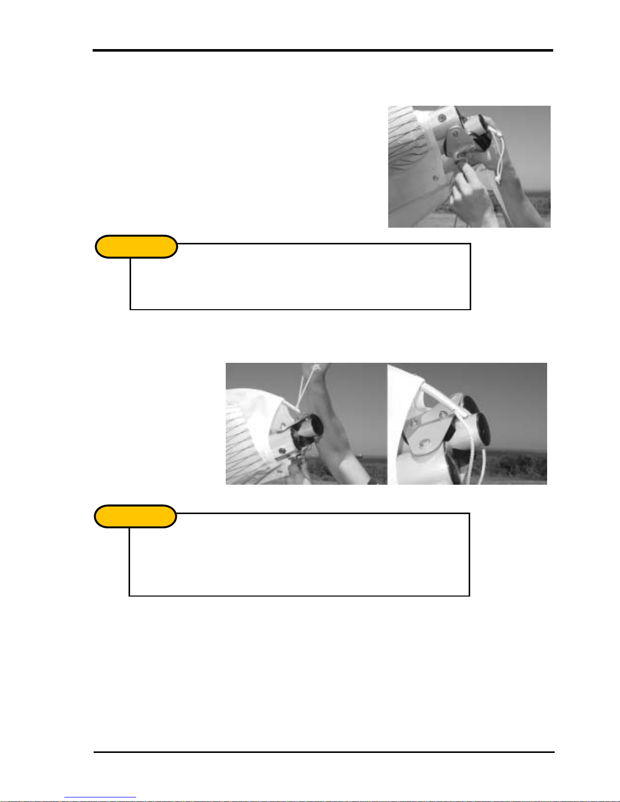
15. Secure the outer wire braced dive strut by rotating it into the sail below the webbing
loop. The action of closing the cord wise zipper creates the loop necessary to hold
the strut in place.
16. Remove the control bar pad and rotate the hangloop ‘dingle-dangle’ such that it is
perpendicular to the keel and the hang loop is not tangled or twisted.
Make sure the tip lever is consistent on both sides. The tip lever should either
be above or below the tip rod when locked in place.
N
O
TE
!
Do not forget this step as it is necessary for stability.
IMP
O
RTANT
!

LITESPORT OWNERS MANUAL
Version 1.01 15
17. Insert the under surface battens through the small holes in the under surface. Once
fully inserted, pull each batten back slightly to secure it within the pocket.
18. Fit the nose fairing using the attached Velcro patches.
Picture 14
Insert the mylar tab on the nose fairing under the leading
edge.
Picture 15
Pull the top rear of the nose fairing towards the rear of the
sail. Securing it in place by the Velcro.
Picture 16
Attach the lower tabs of the nose fairing to the Velcro
on the undersurface.

LITESPORT OWNERS MANUAL
16 Version 1.01
PRE-FLIGHT CHECK
As with most high performance hang gliders, much of the hardware and structure is
enclosed within the sail to improve the aerodynamics of the wing. This means that it is
necessary to inspect the important structural components by looking inside the sail. It is
important to develop a consistent pre-flight routine that incorporates all the necessary
checks. If a distraction interrupts the routine, the pre-flight should be re-started to
ensure that nothing has been missed.
1. As you should have already attached your harness to the glider, check that it is set
up correctly. Ensure that your parachute is mounted correctly and that the bridle
runs cleanly to the carabineer. If your harness height from the base bar needs
adjustment, it is best to acquire the correct length hang loop from your Moyes agent.
2. Move up to the suspension system and verify that the ‘dingle-dangle’ is rotated
perpendicular to the keel and is free from the nose batten pocket. Check the hang
loop and backup.
3. Open the under surface zipper and inspect the cross bar limiting wire. Pull the VG
on and off to confirm that the system is operating smoothly.
4. Inspect the interior of each wing, looking at the back of the leading edges, the cross
bar, and the cross bar junctions.
5. Check the apex of the control frame, ensuring all nuts are secure and thread is
showing beyond the nut. Check that the upper upright end pins are secure.
6. Sight along the keel and move to the nose section where all nuts and bolts should
be checked. Test the nose catch and ensure that the keel batten is located
correctly. Re-attach the nose fairing.
7. Sight along each leading edge to confirm a similar degree of leading edge deflection
(curve). Uneven curves will indicate a bent or damaged tube. While sighting along
the leading edges, check each wing for dive stick symmetry, i.e. equal twist for the
left and right wing.
Check that all internal Velcro’s are attached and are of equal length. If one
side is disconnected or too loose, it may cause a significant turn.
IMP
O
RTANT
!
LITESPORT OWNERS MANUAL
Version 1.01 17
8. Move out along the wing, looking and feeling for any damage. Open the zippers
where the side wires enter the sail and check that the bottom wires are not kinked,
twisted, or damaged. Check the cross bar/leading edge junction bolts and nuts and
verify that the ball joints are not bent. Close the inspection port zippers.
9. Open the long cord wise zippers at the sprog locations and check the entire length
of each dive strut. Check that the wires are not kinked or twisted and that the ball
joints are not bent. Close the zippers.
10. Continue out to the wing tip and make sure the tip levers are properly installed and
that the zippers are closed.
11. Check all the battens as you move along the trailing edge and be sure that the tips
are secure inside the trailing edge pocket.
12. At the keel, check the top VG rope and the cross bar restraining wire. Check that
the rear wires are properly secured by the Bailey Block bolt.
13. Moving across to the other wing, repeat the process as you work your way back to
the nose of the glider. Carefully check the front bottom wires and nose catch before
inspecting the base of the control bar. Check the bottom side wires for broken
strands between the thimble and inner Nico, and just outboard of the outer Nico.
14. Ensure that the control frame assembly bolt passes through the base bar and the
corner knuckle. Check the lower upright end pins.
15. Check that the rigging, nuts, and bolts are in good condition and that the VG rope is
threaded through the jam cleat.
16. Before launching, perform a hang check, ensuring that your legs are through the leg
loops, the harness zippers are working, and that all buckles and clips, etc., are
closed and working.
It is easiest to inspect for tube damage when wings are slightly opened with
no battens in the sail. The entire length of the leading edge tubes can be
easily seen at this stage of the set up procedure through the under surface
zippers and centre zip. It is recommended to check for dents or bends at this
stage of set up before each flight.
N
O
TE
!

LITESPORT OWNERS MANUAL
18 Version 1.01
DE-RIGGING THE LITESPORT
Disassembly of the Litesport is almost a reversal of the set-up procedure. However,
to avoid unnecessary damage a few important points must be remembered.
1. If desired, the Litesport can be disassembled on its keel.
Picture 17
Removing the keel assists with assembly and
disassembly of the glider.
2. Remove the dive sticks from their pockets, and fold towards the outer wing.
3. Remove the nose cone, unload the nose batten, and remove all top battens and all
the under surface battens.
4. Rotate the dingle-dangle so that it is parallel to the keel and attach the protective
padding.
Picture 18
Fit the Dingle Dangle Protector.
5. De-tension and remove the fibreglass tip.
6. Fold the sail tips. There are a number of ways to fold the sail tips. Two such ways
are shown below.
The glider may fall to one side if pushed or blown by the wind. This may result in
wing tip damage. It is recommended that you only use it on flat level ground and
in nil wind. Use with care!
WARNIN
G
!
This manual suits for next models
1
Table of contents
Other moyes Aircraft manuals


