moyes LITESPEED User manual

Moyes Delta Gliders Pty. Ltd.
Version 1.01
LITESPEED
owners manual


LITESPEED OWNERS MANUAL
Version 1.01 1
CONTENTS
Amendments...........................................................................2
Introduction .............................................................................3
Description of Design................................................................4
Specifications ..........................................................................5
Operating Limitations ................................................................6
Disclaimer...............................................................................7
Getting Started ........................................................................8
Assembly Procedures .............................................................11
Pre-Flight Check....................................................................16
De-Rigging the Litespeed.........................................................18
Flying the Moyes Litespeed......................................................22
Tuning Hints..........................................................................26
Performance Tuning...............................................................28
Glider Care...........................................................................30
Maintenance Schedule............................................................32
Sail Removal.........................................................................33
List of Fasteners & Airframe Bolts..............................................34
AN Bolt Index ........................................................................34
Checking The Litespeed Stability System.................................... 35
Purchase Record...................................................................37
Maintenance Log....................................................................37

LITESPEED OWNERS MANUAL
Version 1.01 2
AMENDMENTS
Version
Date
Changes
1.00
24/12
/2002
Conv erted Ow ners Manual to new format.
1.01 28/7/2003 1. Updated all assembly drawings.
2. Corrected page 9 paragraph 4 –referring to the positioning of the
sail w ebbing.

LITESPEED OWNERS MANUAL
Version 1.01 3
Moyes Delta Gliders Pty. Ltd.
1144 Botany Road, Botany NSW 2019 Australia T: +61 (0)2 9316-6466 F: +61 (0)2 9316-8488 E: moyes@moyes.com.au
INTRODUCTION
Thank y ou for choosing the Moy es Litespeed. You hav e chosen w isely.
The Litespeed incorporates the latest high performance hang gliding
design technology.
Since 1967, Moy es Delta Gliders has striv ed to be on the cutting edge of
dev eloping hang gliders of the highest calibre. A family ow ned business
operating under homespun values, w e aim to prov ide a comprehensiv e
international ne tw ork to serv ice all pilots. Even further, w e work with some of
the best pilots in the w orld to ensure that our gliders are stringently made and
tested in order to improve their performance, handling, and safety .
We w ish you the very best fly ing,
The Moyes Team

LITESPEED OWNERS MANUAL
Version 1.01 4
DESCRIPTION OF DESIGN
The Moy es Litespeed is a glider designed by elite competition pilots for competition and
enjoy able high performance cross country fly ing. The Litespeed utilises a similar plan
form as its predecessors the Xtralite and CSX, and has improv ed other facets of the
glider to prov ide better performance, safety and handling.
The Litespeed features a 7075 aluminium airframe which allows minimum w eight w ith
excellent flex characteristics. The leading edge features a step dow n taper design w ith
rev ised sleeving and tube diameters to produce a lighter w eight outer leading edge w ith
improv ed flex distribution across the length. The w eight reduction prov ides considerable
reduction of inertia and thus roll pressures are minimal.
The elliptical fibre glass w ing tip has been a feature of Moy es high performance gliders
since the early 80’s. The fibre glass tip creates a washout distribution allow ing better
turning coordination than conv entional designs. With the full tight VG setting, the fibre
glass tip allows for a tighter mainsail and a more desirable w ashout distribution.
The Litespeed features a rev ised sail design w hich allow s for minimum tw ist w ithout
losing pitch stability . The double surface has been increased to 92% w hich prov ides
better w ashout control under positiv e load and allows the enclosed stability system to be
mounted further rearward for better support. The leading edge tension has been markedly
increased to minimise airfoil distortion at high speeds. Many design steps have been
taken to produce a low minimum fly ing speed and allow easy control at these speeds.
The pitch stability sy stem utilises cable braced inner and outer aluminium sprogs
prov iding support for battens 7 to 11 v ia tw o transversal battens. The inner sprog
features a unique compensator sy stem operating from the geometrical change of the
X-bar to leading edge angle. This allow s for the inner sprog to rise 80mm w hen the VG
is released. The stability system w as designed w ith max imum strength and stiffness in
mind, and demonstrates excellent structural integrity under any flight load.
The Litespeed sail has a total of 8 internal cloth ribs. These internal ribs restrict the
under surface from ‘blow ing out’w hich prev ents pilot induced oscillations. The internal
ribs are cut to a specific airfoil, w hich produces the desired under surface camber for low
drag high speed gliding.
The Litespeed features a spar constructed entirely of pre-impregnated carbon fibre cloth.
The pre-impregnated carbon prov ides maximum consistency in production. The spar
utilises combinations of biax ial fibre and unidirectional fibre to produce load absorbing
flex ibility and maximum impact resistance.

LITESPEED OWNERS MANUAL
Version 1.01 5
SPECIFICATIONS
Model Size Litespeed 3 Litespeed 4 Litespeed 5
Area 12.6sq m
136 sq ft
13.6sq m
146 sq ft
14.5sq m
156 sq ft
Span 9.6 m
31.5 ft
10.0 m
32.8 ft
10.4 m
34.1 ft
Nose Angle 130 to 132 deg 130 to 132 deg 130 to 132 deg
Aspect Ratio 7.2 7.4 7.5
Glider Weight 31.9 kg
70.4 lb
33.6 kg
74 lb
34.5 kg
76 lb
Hook-In-Weight 55-95kg
120-210 lb
68-110kg
150-240 lb
75-120kg
165-265 lb
Packed-Length 4845mm
15’11”
4950mm
16’3”
5150mm
16’11”
Short-Packed Length 4200mm
13’9”
4330mm
14’2”
4500mm
14’9”
C of G Front of Keel 1310mm
51.57”
1363mm
53.66”
1380mm
54.3”
Number of Battens:
Mainsail
Undersurface
21
6
23
6
23
6
VNE 53mph
85kph
53mph
85kph
53mph
85kph
VA 46mph
74kph
46mph
74kph
46mph
74kph
Trim Speed 21mph
34kph
21mph
34kph
21mph
34kph
Stall Speed 16mph
26kph
16mph
26kph
16mph
26kph
Max Speed 77mph
124kph
77mph
124kph
77mph
124kph
Best Glide Speed 28mph
45kph
28mph
45kph
28mph
45kph
Best Glide Angle 15:1 15:1 15:1
Glide Angle 10:1 43mph
69kph
46mph
75kph
45mph
73kph

LITESPEED OWNERS MANUAL
Version 1.01 6
OPERATING LIMITATIONS
Your Moy es Litespeed is a sophisticated state of the ar t high performance hang glider.
If maintained correctly it w ill giv e y ou years of safe enjoy able soaring. How ev er, it is
important that y ou display a healthy respect for all aspects of av iation and that y ou
especially understand the increased risks of fly ing in dangerous conditions or in a
manner that ex ceeds the glider’s operating limitations.
·Flight operation should be limited to non-aerobatic manoeuv res w here the pitch
angle doesn’t exceed 30 degrees up and dow n to the horizon and bank angles don’t
exceed 60 degrees
·The Moyes Litespeed has been designed for foot launched soaring flight and should
not be flow n by more than one person at a time
·It should not be flow n backwards or inverted
·The recommended minimum pilot skill level is Adv anced (Hang 4)
·The Moyes Litespeed should not be flow n w ith auxiliary pow er
·The Moyes Litespeed should not be flow n in excess of the placarded VNE or VA
·VNE (speed nev er to exceed): 53 mph / 84.8 kph
·VA (max imum rough air manoeuvring speed): 46 mph / 73.6 kph
·Stall speed w ith max imum pilot w eight: Less than 25 mph / 40 kph
·Max imum speed with minimum pilot w eight: Less than 55 mph / 80 kph
The Moyes Litespeed will resist spinning and w ill recov er quickly if control pressures are
relax ed. Recovery from a stalled turn can be achiev ed w ithout ex treme height loss or
w ithout ex treme attitude change if the angle of attack is reduced. Recov ery from such an
incipient spin w ill be achiev ed within half a turn if the angle of attack is low ered to a
normal fly ing angle.
The Moy es Litespeed has been tested and certified to the USHGMA and DHV
standards. These standards require ultimate load tests at:
·Max imum lift angle of attack at a speed of 65 mph / 104 kph
·Negativ e 30 degrees angle of attack at a speed of 46 mph / 73.6 kph
·Negativ e 150 degrees angle of attack at a speed of 32 mph / 51.2 kph
·Pitching moment tests at 20/32, 37/59 and 54/86 mph/kph respectiv ely, to display
the gliders inherent positiv e pitch stability through a broad range of angles of attack
The Moyes Litespeed is capable of easily fly ing at speeds greater than the VA and VNE.
We recommend y ou use an accurate airspeed indicator and familiarise y ourself w ith
control bar positions at these speeds and normal fly ing speeds.

LITESPEED OWNERS MANUAL
Version 1.01 7
DISCLAIMER
The ow ner and operator must understand that due to the inheren t risk inv olv ed in fly ing
such a unique vehicle, no w arranty is made or implied of any kind against accidents,
bodily injury or death. Operations such as aerobatic manoeuv res or erratic pilot
technique may ultimately produce equipment failure, and are specifically excluded from
the w arranty.
This glider is not cov ered by product liability insurance, nor has it been designed,
manufactured or tested to any state or federal gov ernment airw orthiness standards
or regulations.
LITESPEED OWNERS MANUAL
Version 1.01 8
GETTING STARTED
Your new Moy es Litespeed may have been shipped to y ou in the 4.5 metre breakdow n
form. If so, y ou can assemble your glider to its full length by follow ing the assembly
procedures. All references to ‘top’& ‘bottom’and ‘left’and ‘right’are referred to w ith the
glider in fly ing mode.
Please check your packing list.
·Glider
·2 x Back section leading edges: note that the back sections are different betw een
left and right
·1 x Batten Set: Right=Green/Left=Red/Blue=Undersurface
·1 x Speed Bar
·2 x Tip Bags
·3 x Padding Pieces: A-Frame top & bottom, Keel sleev e
·1 x Batten Pattern
·1 x Snack Pack with ow ner’s manual and Batten Profile
Assembly from 4.5m Breakdown Form
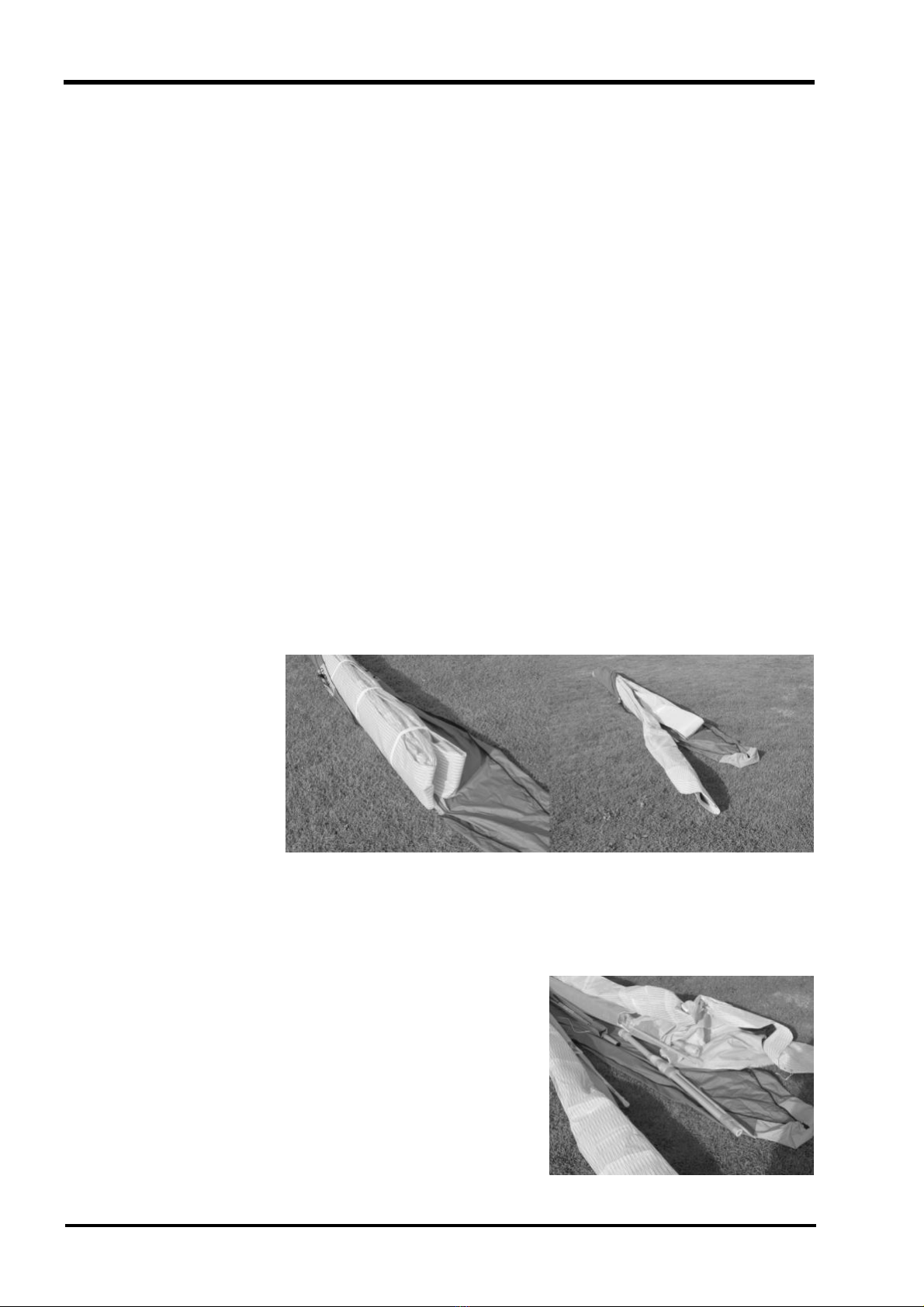
1. Open the glider bag and roll the glider onto its undersurface.
Undo the straps and ex tend the sail.
Picture 1
Lay the glider on
its undersurface
and unfold the sail.
2. Ex pose the leading edge/cross bar junction through the inspection zip. Remov e the
bubble w rap and tape from the leading edge/cross bar junction and the end of the
middle sleeve.
Picture 2
Remove packing materials from leading edge end.
LITESPEED OWNERS MANUAL
Version 1.01 9
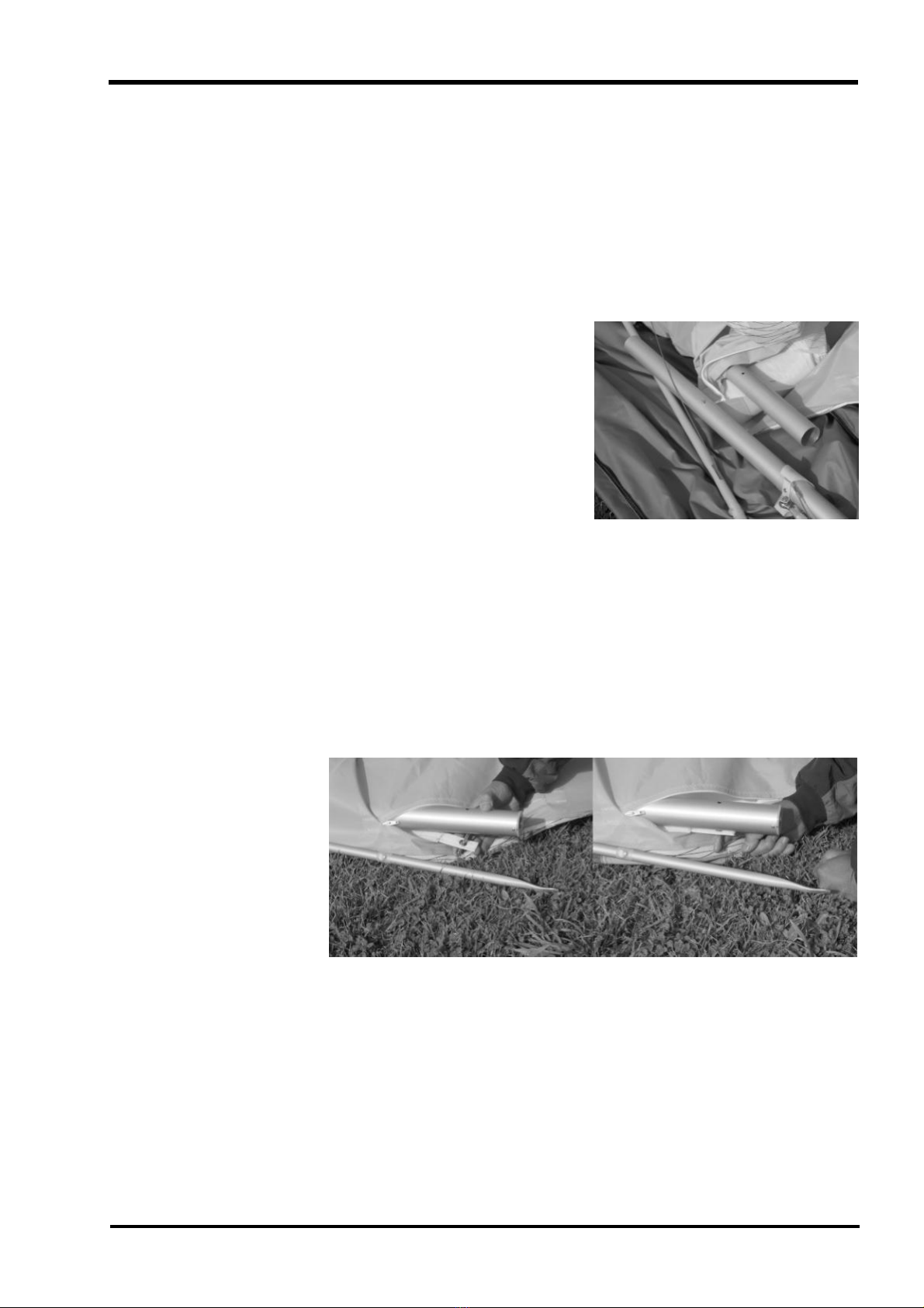
3. Insert the right hand back section of leading edge. The right hand back section
differs from the left in the mounting of the outer sprog. You can check this by
picturing that the cable must be on the top side of the leading edge and the sprog
must fold inboard. Push the back section into the mid sleev e w hile depressing the
push button pin. Continue to push the back section in until it reaches its stop, then
rotate the back section until the mid sleev e location holes align w ith the push
button pin. Closely check that the push button pin has fully released and that the
back section is secure against rotation forces.
Picture 3
Insert the back
ends of the
leading edge.
4. Secure the sail by attaching to the tip w ebbing using the clevis pin and ring supplied.
Insert the pin through the w ebbing and into the bottom hole at an angle. Straighten
the clev is pin w hile sliding the w ebbing tow ards the leading edge as show n in
Picture 4. Ensure the tip w ebbing is not tw isted and is on the bottom of the leadin g
edge.
Picture 4
Insert sail pin into end of leading edge.

LITESPEED OWNERS MANUAL
Version 1.01 10
5. Repeat steps 1-4 to install the left hand back section of leading edge.
Your Litespeed w ill now be ready for the standard assembly. Before flight, make
a thorough inspection of all tubing and nu ts and bolts to ensure no damage has
occurred during transportation. (refer to section on pre-flight check).
Picture 5
Assembled glider
showing dive sticks
extruding from under
surface zippers.
The inner and outer sprogs must exit the sail from the large cord w ise zippers.
The zippers must be opened w hen the glider is in standard break dow n form
w ith both sprogs folding tow ard the wing tip outside the sail.
IMPORTANT
!
LITESPEED OWNERS MANUAL
Version 1.01 11
ASSEMBLY PROCEDURES
1. Place the glider on the ground, zipper up. Open the bag, undo ties, remove A-frame
bottom padding and battens.
2. Assembly the A-Frame.
Picture 6
Standard uprights and
base bar assembly.
Roll the glider over so that
it is standing on the
control frame.
3. Roll the glider over so that it is standing on the control frame.
Picture 7
Roll the glider onto the
A-frame and attach the
front wire to the Bailey Block.
Take special care with the w ires, the Litespeed features 1x 19 cable w hich can
easily be kinked unless special care is taken.
NOTE
!
With standard uprights, the uprights will naturally toe-in as show n in
Picture 6. Hold the base bar and the upright, tw isting the upright so the
connection lines up.
NOTE
!

LITESPEED OWNERS MANUAL
Version 1.01 12
After initial assembly it is suggested that the nose batten be left in but pulled
out slightly and left beside the nose plate for pack-up. Check that the nose
batten sits ov er the lug on the keel securely.
NOTE
!
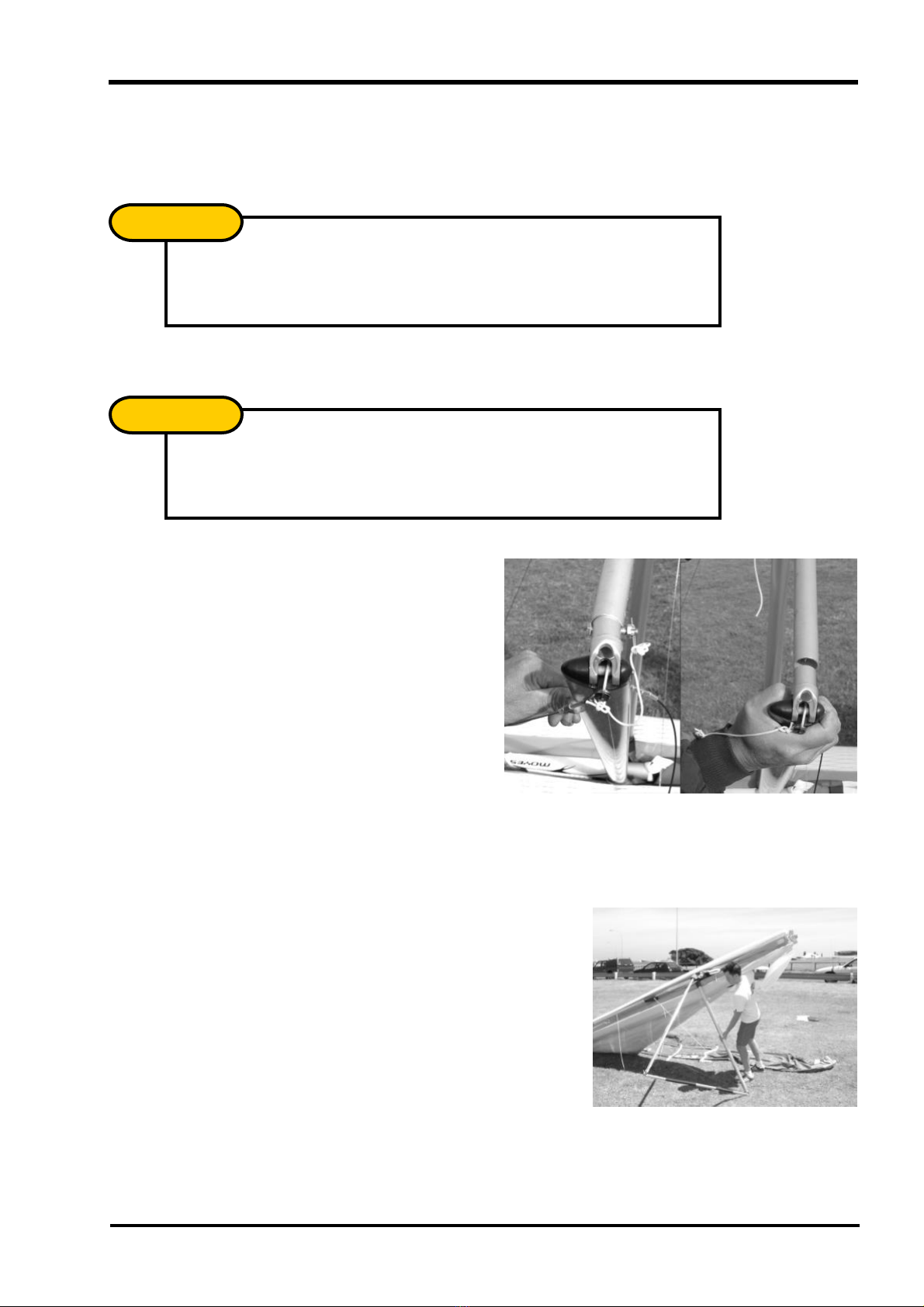
4. Insert the ring of the low er front w ires in the Bailey Block making sure that the spring
is firmly locked and the w ires untw isted.
Picture 8
Attaching the front wires to the Baileys Block.
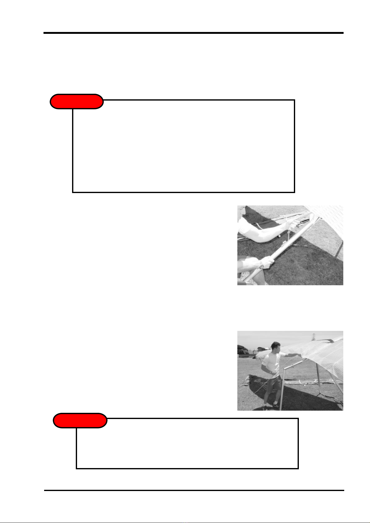
5. Insert the nose batten. The batten may need some “feeding”through the Sail by
pulling the sail forw ard to remove any wrinkles as the batten slides into its pocket.
Picture 9
Insert nose batten.
6. Carefully spread eachw ing making sure that y ou do not raise them above the keel.
Picture 10
Spread the wings.
Check bottom w ires are not tw isted or kinked.
NOTE
!
LITESPEED OWNERS MANUAL
Version 1.01 13
DO NOT USE EXCESSIVE FORCE WHEN TENSIONING THE GLIDER.
If ex cess force is encountered check:
üThe sidew ires are not tw isted or kinked
üThe cross bar retainer wire is not caught on the nose plate assembly
üThe floating cross bar centring wire is not caught on a cross bar
assembly junction
üThe pull back w ire or VG pulleys are not caught in the hang loop assembly
7. To tension the crossbar, pull the cord coming out of the keel aft of the sail.
Check that the cable and rope are not tw isted and tha t the spring lock is firmly
locked. In strong w inds the glider can be particularly difficult to tension. Hav e a
helper gently raise and pull one w ing, this reduces the pressure on the centre
section and allows it to slide more freely .
Picture 11
Tension the glider.
8. The Litespeed is equipped w ith a remov able keel aft section. The glider can be left
resting on it, facilitating the fitment of the w ashout struts, and battens. If desired, the
glider may now be raised onto its keel to complete the assembly. This also assists
w ith keeping the sail clean by keeping the tips off the ground.
Picture 12
Raising the glider onto the keel can make assembly
easier and keeps the sail clean.
WARNING
!
The glider may fall to one side if pushed or blow n by the wind - this may result in
w ing tip damage. It is recommended that y ou only use in flat lev el ground and in
nil w ind. Use with care!
WARNING
!

LITESPEED OWNERS MANUAL
Version 1.01 14
9. Insert battens gently from the root tow ards the mid span, battens 1-6 only for the
Litespeed 4 & 5, battens 1-5 only for the Litespeed 3. Use only gentle pressure
w hen inserting the battens, this w ill greatly ex tend the longev ity of the ba tten
pockets. Red tipped numbered battens are for the left w ing, green for the right, and
blue the under surface.
Picture 13
Insert battens #1 to # 6
10. Open zipper at sail tip to allow access to inside of sail. Slide fibre glass rod through
end of sail and locate in the end of the leading edge. Ensure that the fibre glass rod
is pushed hard against its stop.
Picture 14
Inserting tip and fitting aluminium cap.
11. Fit aluminium cup of the tip lev er to the end of the tip rod and tension tip by rotating
the flat end of the tip lev er inboard. For ex tra lev erage, place your thumb through the
loop that is attached to the end of the tip lev er. Make sure the tip lev er is locked
against the tip rod. Close the zipper.
Picture 15
Tension the fibre glass wing tip.
Make sure the tip lev er is consistent on both sides. The tip lev er should either
be abov e or below the tip rod when locked in place.
NOTE
!

LITESPEED OWNERS MANUAL
Version 1.01 15
12. Insert the remaining mainsail battens, 7 to 11 on the Litespeed 4 & 5 and 6 to 10 on
the Litespeed 3.
13. The battens hav e been adjusted in the factory, but may need to be readjusted upon
initial assembly. The batten tips simply screw into the end of the batten, therefore
the batten tension can be adjusted by either screwing the tip in or out.
The outer batten on each w ing should be fitted w ith additional tension. Continue to
make minor adjustments to the outer batten tension until any w rinkles have been
remov ed from the upper surface.
Picture 16
Adjust the batten end so that it slightly
extends past the trailing edge.
14. Locate the inner and ou ter w ire braced div e struts by placing them inside the sail,
below the w ebbing loop. Note that the action of closing the cord-w ise zipper creates
the loop necessary to hold the strut in place.
15. Insert the under surface battens (blue) into their respectiv e pockets.
16. Fit the nose fairing using the Velcro to keep a clean trim finish.
Picture 17
Fitting the nose nappy.
Do not forget this step as it is necessary for stability.
IMPORTANT
!
LITESPEED OWNERS MANUAL
Version 1.01 16
PRE-FLIGHT CHECK
As w ith most high performance hang gliders, much of the hardw are and structure is well
enclosed to giv e a streamlined finish to the w ing. This means that y ou must look inside
the sail to check many of the important structural components. You should develop a
consistent routine that incorporates all the necessary checks. If y ou are distracted during
the routine, y ou should start again to ensure nothing has been missed.
1. As y ou should have already attached y our harness to the glider, check that it is set
up correctly . Ensure that y our parachute is well maintained and stowed appropriately
and that the bridle runs cleanly to the carabineer w hich is attached v ertically to the
hang loops. If y our harness height from base bar needs adjustment, it is best to
acquire the correct length loop from y our Moy es dealer.
2. Mov e up to the suspension system and verify that the dingle-dangle is rotated
perpendicular to the keel and is free from the nose batten pocket. Check hang loop
and backup.
3. Open the under surface zip and inspect the cross-bar retainer w ire. Pull the VG on
and off a few times to check that the crossbars are moving freely and the VG system
is operating smoothly and is tied firmly to the clip. Inspect the interior of each w ing,
looking at the back side of the leading edges, the crossbar, and the crossbar
junctions. Check that the cross bar centring w ire is free. This wire is partly loose in
VG full off and should become tight w hen VG is 3/4 on.
4.
5. Check the apex of the control frame ensuring all nu ts are secure and thread is
show ing beyond the nut on the bolt end.
6. Sight along keel and mov e to the nose section, checking all nuts and bolts.
Test nose catch and ensure keel batten is located correctly . Re-attach nose fairing.
7. Sight along each leading edge to confirm a similar amount of leading edge
deflection (curv e). Unev en curves will indicate a bent or damaged leading edge.
While sighting dow n the leading edges check each wing for div e stick symmetry , ie.
equal tw ist for left and right w ing.
Check that all internal Velcro’s are attached and are of equal length. If one
side is disconnected or too loose, it may cause a significant turn.
IMPORTANT
!
It is easiest to inspect for tube damage w hen w ings are slightly opened w ith
no battens in the sail. The entire length of the leading edge tubes can be
easily seen at this stage of the set up procedure through the under surface
zippers and centre zip. It is recommended to check for dents or bends at this
stage of set up before each flight.
NOTE
!

LITESPEED OWNERS MANUAL
Version 1.01 17
8. Mov e out along the w ing looking and feeling for any damage. Open the zip w here
the side w ires enter the sail and check that bottom w ires are not kinked, tw isted or
damaged. Check the cross-bar/leading edge junction bolts and nuts and check that
the ball joint is not bent. Close zip on inspection port.
9. Open the long cord-w ise zippers at sprog location and check both the front and rear
of each div e strut. Check that the w ires are not kinked or tw isted and check that the
ball joint thread is not bent. Close zip.
10. Continue out to w ing tip and make sure the tip lev ers are properly installed and that
the zipper is closed.
11. Check all battens as y ou mov e along the trailing edg e and be sure that the spring
tips are secure inside of the trailing edge pocket.
12. At the keel, check the top VG rope and the cross-bar restaining w ire. Check that
rear w ires are properly secured by the Bailey Block bolt.
13. Mov ing across to the other w ing, repeat the process as y ou work your w ay back to
the nose of the glider. Carefully check the front bottom w ires and nose catch before
inspecting the base of the control bar. Check bottom side w ires for fray ed strands
betw een thimble and inner nico, and just outboard of the outer nico.
14. Ensure that the control frame assembly bolt passes through the base bar and the
corner knuckle.
15. Check the rigging, nuts, and bolts are in good order and that the VG rope is
threaded through the jam cleat and is secure.
16. Re-check harness, hang loops, and carabineer.
17. When finally preparing to fly , do a proper hang check ensuring that legs are through
leg loops, that harness zippers w ork, and that all buckles or clips etc. are closed and
w orking. Look again at your hangloops and carabineer(s ).
LITESPEED OWNERS MANUAL
Version 1.01 18
DE-RIGGING THE LITESPEED
Disassembly of the Litespeed is virtually an ex act reversal of the set-up procedure,
how ever, a few important points must be remembered to av oid unnecessary damage.
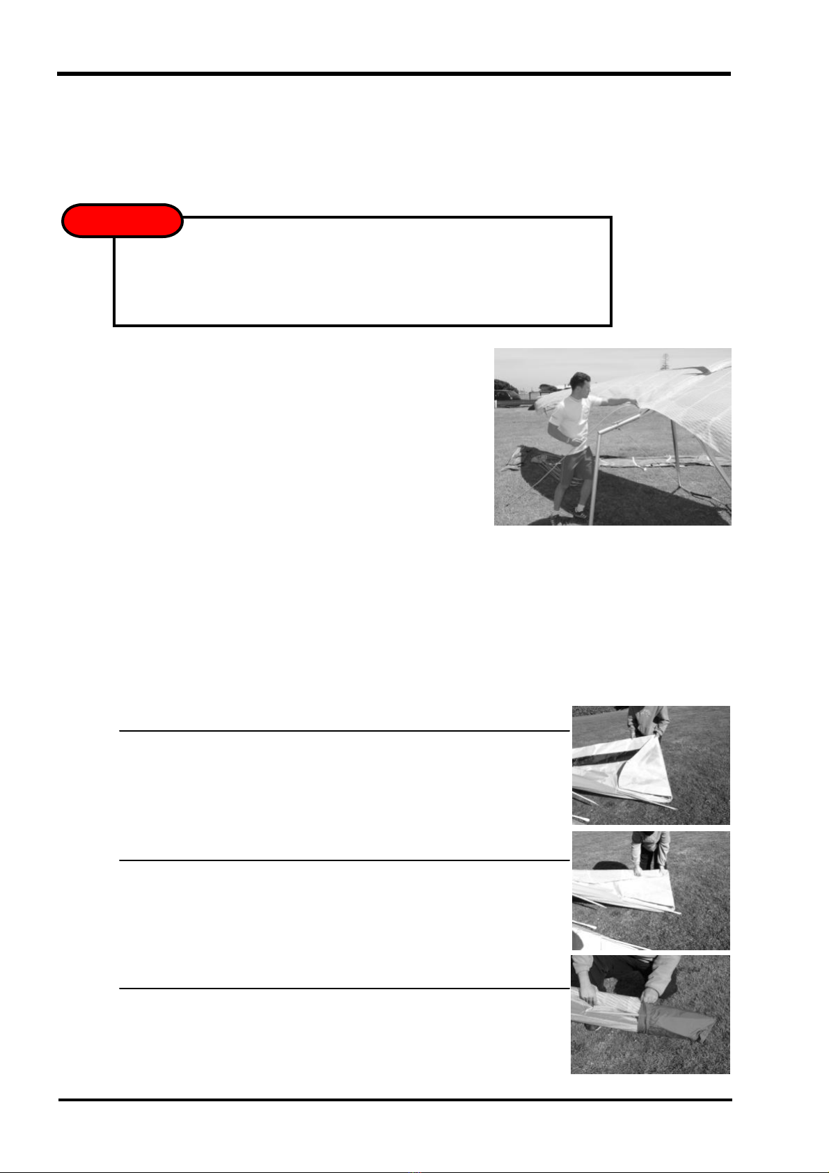
1. If desired, the Litespeed can be disassembled on its keel.
Picture 18
Removing the keel assists with assembly
and disassembly of the glider
2. Remov e all battens starting from the tips, all the under surface battens, and the
glass tips. Place all battens in the batten bag.
3. Fold the sail tips
There are a number of w ays to fold the sail tips. Tw o such ways are shown below.
Folding the Sail Tips - M ETHOD 1
·Fold the leading edge back onto itself.
·Roll the sail up from the trailing edge tow ards the leading edge.
·Fit the sail and the outer div e strut into the boot.
The glider may fall to one side if pushed or blow n by the wind. This may result in
w ing tip damage. It is recommended that y ou only use it on flat lev el ground and
in nil w ind. Usew ith care!
WARNING
!
Other manuals for LITESPEED
1
This manual suits for next models
3
Table of contents
Other moyes Aircraft manuals


