MPA Mini Series Instruction manual

ADJUSTABLE
MULTISPINDLE
HEADS
MANUAL ON USE
AND MAINTENANCE
TOOLS TO SHAPE THE WORLD
MADE IN
ITALY
COMUNITÀ
EUROPEA

UT1811 - 1010 - UK01
Page 2/32
ADJUSTABLE MULTISPINDLE HEADS
Page 2/32
Dear Customer,
We thank you for having chosen MPA and we hope that it fully satisfies your expectations,
guaranteeing a high quality production.
We kindly request you to read the instructions provided in this manual before starting to use
the product, as they provide important information on how to use and service the product in
absolute safety.
This manual also provides the technical features of the product, (also visible on the website:
www.m-p-a.it).
All rights reserved; this manual can be reprinted or reproduced only prior to formal written
authorisation by MPA srl.
Yours faithfully
MPA srl
Introduction

UT1811 - 1010 - UK01
Page 3/32
ADJUSTABLE MULTISPINDLE HEADS
Page 3/32
Manufacturer’s declaration
EEC MACHINE DIRECTIVE
MANUFACTURER’S DECLARATION
MPA srl
Via Pizzoli, 3 - Bargellino Cà Bianca
40012 Calderara di Reno (Bo) Italy
in the Person of the Legal Representative
declares that the adjustable multispindle heads
are compliant with the provisions of the
Machinery Directive 2006/42/EC
and forbids the start-up
before the machine in which the special series head
has to be fitted in is declared compliant with
Machinery Directive it self.
Signature of issuer
Marco Ceneri
EUROPEAN
COMMUNITY

UT1811 - 1010 - UK01
Page 4/32
ADJUSTABLE MULTISPINDLE HEADS
General warranty conditions
Page 4/32
General warranty conditions
Proper use and maintenance of the head will ensure that it stays in good working order.
Any modification, tampering, or improper use relieves MPA from all liability for accidents or
damage to persons or things occurring during the use the head.
MPA guarantees this product against material and manufacturing defects for a period of 12
months, considering ordinary usage. The use of non-original spare parts or failure to follow
the instructions provided in this manual will void the warranty. MPA guarantees exclusively
the repair or replacement of parts found to be defective by its service centre. MPA remains at
your complete disposal for any clarification and to provide any technical support necessary
for achieving the best performance of the head.
MPA reserves the right to make any modifications to all parts that are believed to be necessary
to improve the quality of the product without prior notice.

UT1811 - 1010 - UK01
Page 5/32
ADJUSTABLE MULTISPINDLE HEADS
Index
INDEX
Introduction....................................................................................................................2
Manufacturer’s declaration.............................................................................................3
General warranty conditions..........................................................................................4
1 GENERAL NOTES........................................................................................................7
1-1 Purpose of the document......................................................................................7
1-2 Symbols ................................................................................................................7
1-3 Main information ...................................................................................................8
1-4 Standard references .............................................................................................8
1-5 Noise level ............................................................................................................8
1-6 Packaging .............................................................................................................8
1-7 Transport...............................................................................................................9
1-8 Storage .................................................................................................................9
1-9 Disposal ................................................................................................................9
2 IDENTIFICATION ........................................................................................................11
2-1 Manufacturers’ Data............................................................................................11
2-2 Head identification data ......................................................................................11
3 MAIN DESCRIPTION..................................................................................................13
3-1 Intended use .......................................................................................................13
3-2 Improper use.......................................................................................................13
4 SAFETY RULES .........................................................................................................15
5 TECHNICAL FEATURES............................................................................................17
6 MACHINE CONNECTION ..........................................................................................19
6-1 Heads suitable for installation to units and drilling/tapping machines.................19
6-2 Special applications ............................................................................................20
7 INSTALLATION...........................................................................................................21
7-1 Balancing ............................................................................................................22
8 ADJUSTMENT............................................................................................................23
9 ASSEMBLY TOOLS AND ADJUSTING......................................................................25
9-1 ER collet DIN 6499 shape B ...............................................................................25
9-2 Tools adjustment and clamping ..........................................................................26
10 MAINTENANCE..........................................................................................................27
10-1 Personnel in charge ............................................................................................27
10-2 Scheduled maintenance .....................................................................................27
11 AFTER-SALES SERVICE AND SPARE PARTS ........................................................29
11-1 Customers service..............................................................................................29
11-2 Spare parts service.............................................................................................29

UT1811 - 1010 - UK01
Page 6/32
ADJUSTABLE MULTISPINDLE HEADS
Index
UT1811 - 1010 - UK01
Page 7/32
ADJUSTABLE MULTISPINDLE HEADS
1 General notes
1 GENERAL NOTES
1-1 Purpose of the document
The information in this manual has been provided to highlight the operations necessary for
the end user to correctly use and service the MPA heads. Information concerning installation,
adjustment and maintenance relating to the head you have purchased can be found in this
document.
Special attention has been given to questions matters involving the safety and safeguard of
the operators’ security, together with the safeguard and respect of the work area.
Before using the multispindle head, read carefully this manual and, in case of doubts, contact
the MPA After-sales technical service.
1-2 Symbols
In order to direct the readers’ attention on particularly important points in this manual, the
following graphs have been used:
DANGER Indicates an operation that must be carried out scrupulously in that it may
expose the operator to serious injuries.
IMPORTANT Indicates an operation that may cause damages to the adjustable head,
or simply recall the attention of the reader on certain particularly important
operations.
ADJUSTMENT Indicates adjusting operations. The operations marked with this symbol must
be carried out by technically qualified staff and with adequate mechanical
knowledge.

UT1811 - 1010 - UK01
Page 8/32
ADJUSTABLE MULTISPINDLE HEADS
1 General notes
1-3 Main information
To obtain maximum product yield in time, we recommend complying with the following
notes:
• Ensure to have correctly installed the multispindle head to the machine.
While choosing the connection to the tool machine, verify compatibility with the
declared performances.
The MPA head can be fitted to a tool machine equipped with regulatory accident-
prevention protections and in compliance with Machinery Directive 2006/42/EC.
• Absolutely avoid any improper use of the equipment and work with care and attention.
• Carry out regularly all routine maintenance interventions (see chap. 10).
• Use only original MPA spare parts (see chap. 11).
1-4 Standard references
The MPA head you have purchased is compliant with Machinery Directive 2006/42/EC (ex
98/37/EC).
1-5 Noise level
The MPA head complies with current Standards with regard to noise levels.
The manufacturer of the machine on which the head is fitted must provide the data
concerning the noise levels in the relative manual.
1-6 Packaging
The multispindle head you have purchased is supplied packed in cardboard boxes and
protected with shock-resistant protections.
IMPORTANT Upon receipt, check that the supply corresponds to the order specifications and
that no damages have occourred during the transport. In case of anomalies,
do not use the head and contact the manufacturer immediately.
Packaging must be disposed of in compliance with the local waste disposal Standards.

UT1811 - 1010 - UK01
Page 9/32
ADJUSTABLE MULTISPINDLE HEADS
1 General notes
1-7 Transport
During transport, keep in mind that you are handling a precision tool requiring adequate
caution. When carrying out the operation, observe the safety Standards in force with regard
to safety at work.
DANGER Do not disassemble, transport or re-assemble the head with tools fitted in
the spindles, as the sharp cutting parts could cause injuries.
For models with a weight above 10 kg, use a suitable hoisting mean for the operation.
1-8 Storage
In case you don’t use the head for a long time, it is a good rule to clean the head and to
protect it against salty, damp or chemically aggressive environments.
IMPORTANT
For inactivity periods of more than 6 months,before start-up, we recommend
to replace the lubricant inside the head (see chap. 10).
1-9 Disposal
The MPA heads are manufactured using the following substance:
• aluminium;
• steel;
• cast iron;
• lubricants.
IMPORTANT The head must be disposed of per type of substance, in strict compliance with
the legal regulations with regard to recycling and management of waste in
force in the country where the head is used.
In particular, exhaust lubricants must not be thrown outdoors but must
be handed over to specialised and authorised waste collection centres.

UT1811 - 1010 - UK01
Page 10/32
ADJUSTABLE MULTISPINDLE HEADS
1 General notes
UT1811 - 1010 - UK01
Page 11/32
ADJUSTABLE MULTISPINDLE HEADS
2 Identification
2 IDENTIFICATION
2-1 Manufacturers’ Data
MPA srl
Via Pizzoli, 3 Bargellino Cà-Bianca
40012 Calderara di Reno (Bo) Italy
VAT Number 00522081207
Tax Code 00739970374
+39 (051) 727073 +39 (051) 727730
[email protected] www.m-p-a.it
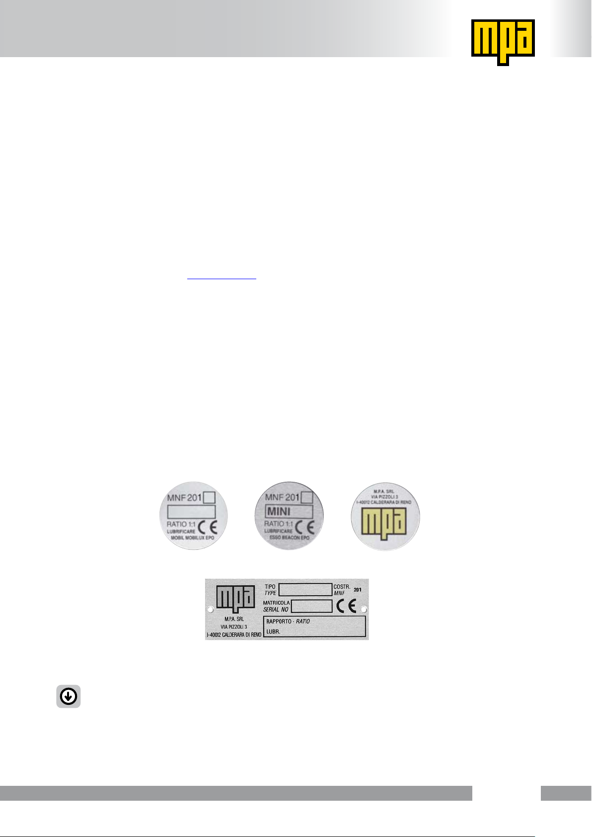
2-2 Head identification data
An aluminium identification nameplate is fitted on each MPA head indicating the main features
of the product. Fig. 1 illustrates example of identification nameplates displaying the data that
should be written on it.
As each model of MPA head is different in shape and size, the position and the shape of the
identification nameplate will vary depending on the model. It will could be of adhesive type
or riveted on one of the external surfaces.
Fig. 1
IMPORTANT It is forbidden to remove or tamper with the identification nameplate.

UT1811 - 1010 - UK01
Page 12/32
ADJUSTABLE MULTISPINDLE HEADS
2 Identification

UT1811 - 1010 - UK01
Page 13/32
ADJUSTABLE MULTISPINDLE HEADS
3 Main description
3 MAIN DESCRIPTION
The adjustable multispindle head you have purchased is composed as follows:
Fig. 2
ADJUSTABLE
SPINDLE
FASTENING SCREW
HEAD MAIN
BODY
ADJUSTABLE
SPINDLE UNIT
ADJUSTABLE
SPINDLE UNIT
VERSION WITH
ER COLLET
DIN 6499 shape B
VERSION WITH
SPINDLE
DIN 55058
3-1 Intended use
• The MPA heads have been designed and manufactured to drill, tap, chamfer and mill
(for 900 series), metal, plastic and wood materials. Any other use is to be considered
improper and relieves MPA from all liabilities.
3-2 Improper use
• The MPA heads are not suitable for tapping by means of interpolation.
Any different use to those indicated in point 3-1 of this manual, is to be considered improper
and, therefore, unauthorised, and relieves MPA from every liability for damages to persons
or things.

UT1811 - 1010 - UK01
Page 14/32
ADJUSTABLE MULTISPINDLE HEADS
3 Main description

UT1811 - 1010 - UK01
Page 15/32
ADJUSTABLE MULTISPINDLE HEADS
4 Safety rules
4 SAFETY RULES
• Before starting the tool machine, make sure that the head is correctly connected to the
machine and, consequently, that there is no risk of it releasing and falling off.
• Wear always industrial safety gloves when handling. Be sure that no cutting tools are
in the spindles. Don’t power up the head while carrying out service. Disassemble the
multispindle head, as the sharp parts may cut or injure the personnel.
• Don’t touch the head when it is moving. Any adjustments and interventions must be carried
out when the machine is inactive and in absolute safe conditions for the operator.
• The operating machine on which the MPA head is fitted, must be manufactured in
compliance with current safety Standards. All operator safety guards must be correctly fitted
and efficient and approved according to Machinery Directive 2006/42/EC (ex 98/37/EC).
The design of these safety guards is under the sole responsibility of the Manufacturer of
the machine on which the head is fitted; safety parameters must be cheched exclusively
by the factory manager where the head is used.
• Suitable clothing for workshop jobs must always be worn when using the MPA head.
It is therefore forbidden to wear ties, necklaces and any other non-adhering clothes or
accessories that may create a hazard.
The safety at work Standard in force must be complied with.
• During cleaning operations, especially when compressed air is being used, proceed with
caution and wear safety goggles or other suitable means of protection.
• The maximum rotation speed or the maximum spindle torque must not be exceeded (see
data published on the official website www.m-p-a.it).
Keep always transmission and rotation direction ratio under control; the values are shown
both on the nameplate and on the attached technical drawing.
• The use manual must always be kept handly where the head is being used. You also
must comply with the precautions in this manual, the general and local Standards in force
regarding accident prevention, and environmental protection.
DANGER If tools involving consistent rotating cams are used, operate at rotation speeds
such to prevent the centrifugal force created by the cams from compromising the
integrity of the spindle.
MPA engineering department is always at your complete disposal for any
advice on ideal operating conditions.

UT1811 - 1010 - UK01
Page 16/32
ADJUSTABLE MULTISPINDLE HEADS
4 Safety rules
• The forward movement speed of the tool must be adjusted so that no excessive axial
force is put on the tool, which could cause it to collapse with the consequent hazardous
cast-off of chips of material.
• Check the conditions and state signs of wear on the tool.
• Any anomalies on the head may cause serious damages and reduce significantly the life-
time and precision of the head. When in doubt, always contact MPA.
• The normal temperature of the head while it is working must not tendentiously exceed
60°C. Only during the first 100 hours of use the temperature can increase its maximum
value by about 25%.

UT1811 - 1010 - UK01
Page 17/32
ADJUSTABLE MULTISPINDLE HEADS
5 Technical features
5 TECHNICAL FEATURES
Sizes and technical features are available on the official website www.m-p-a.it.

UT1811 - 1010 - UK01
Page 18/32
ADJUSTABLE MULTISPINDLE HEADS
5 Technical features

UT1811 - 1010 - UK01
Page 19/32
ADJUSTABLE MULTISPINDLE HEADS
6 Machine connection
6 MACHINE CONNECTION
6-1 Heads suitable for installation to units and drilling/tapping
machines
• The power transmission works by means of driver and joint, depending on the type of
connection of the machine spindle.
Fig. 3 shows the different connection systems between the machine and the adjustable
multispindle head.
Fig. 3
CONNECTION
COUPLING
FLANGE
JOINT FOR
ISO SPINDLES
DRIVER FOR
SPINDLES DIN 55058
DRIVER
DIN 238
DRIVER
MORSE TAPER
JOINT
DRIVER FOR
SPINDLES
WITH COLLET
ADJUSTABLE
MULTI SPINDLE
HEAD

UT1811 - 1010 - UK01
Page 20/32
ADJUSTABLE MULTISPINDLE HEADS
6 Machine connection
6-2 Special applications
For other special connection, contact MPA Technical Department.
This manual suits for next models
15
Table of contents


