RIVENUTDRILL - User Manual • 5
EN
FR
PL
IT
9. Press the trigger until blind rivet is fastened.
10.When rivet stem breaks, release the trigger.
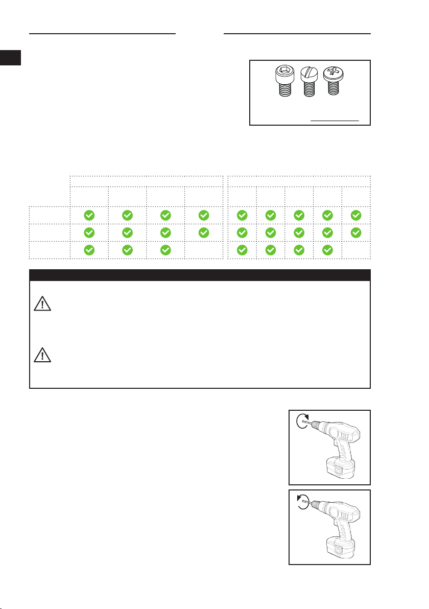
11.Switch power drill to rotate in counterclockwise direction.
12.Grip and hold the drill attachment firmly and then press trigger of the power drill.
13.When <click, click> sound is heard, release the trigger.
14.Point the power drill in downward direction and the rivet stem should fall out.
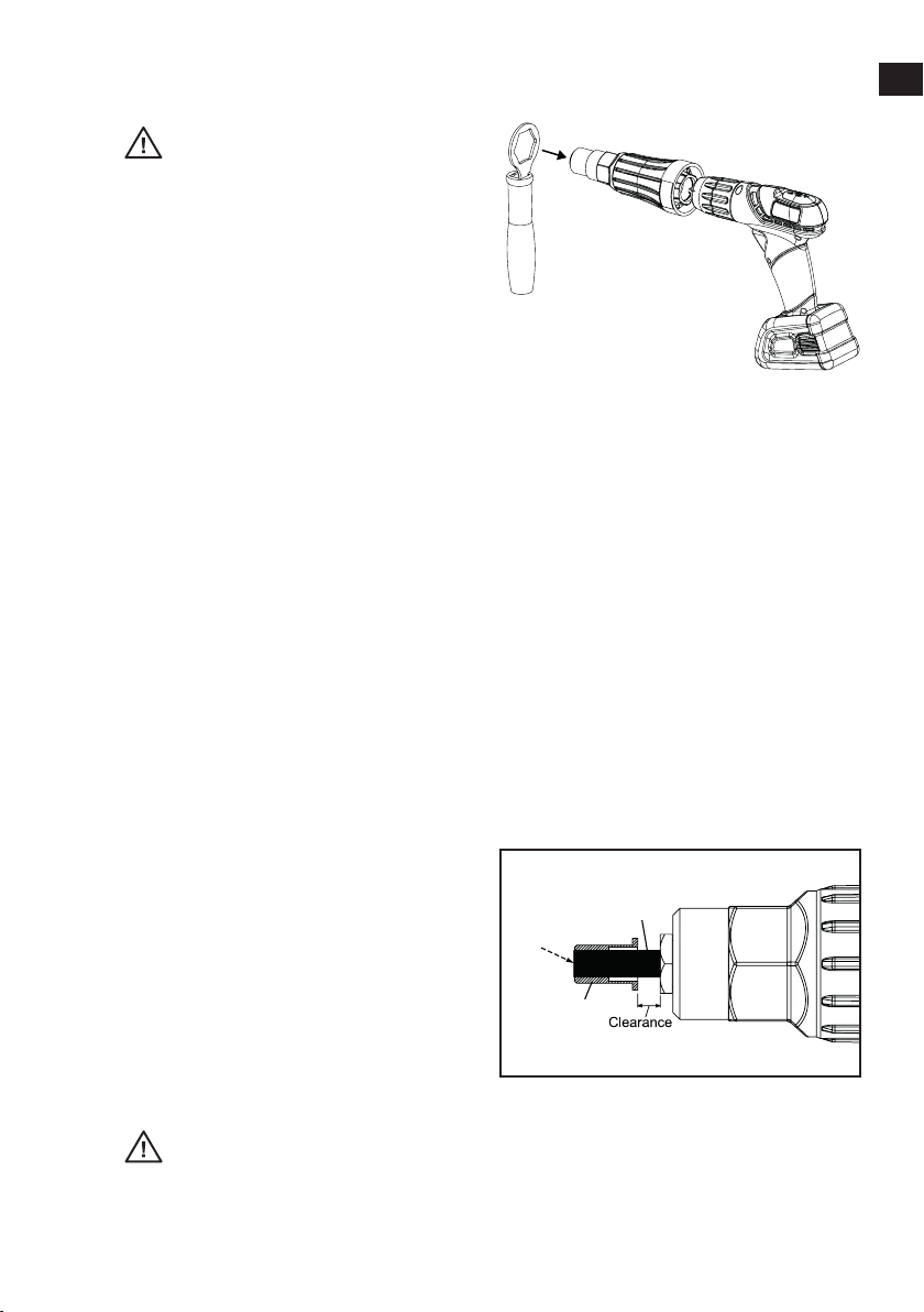
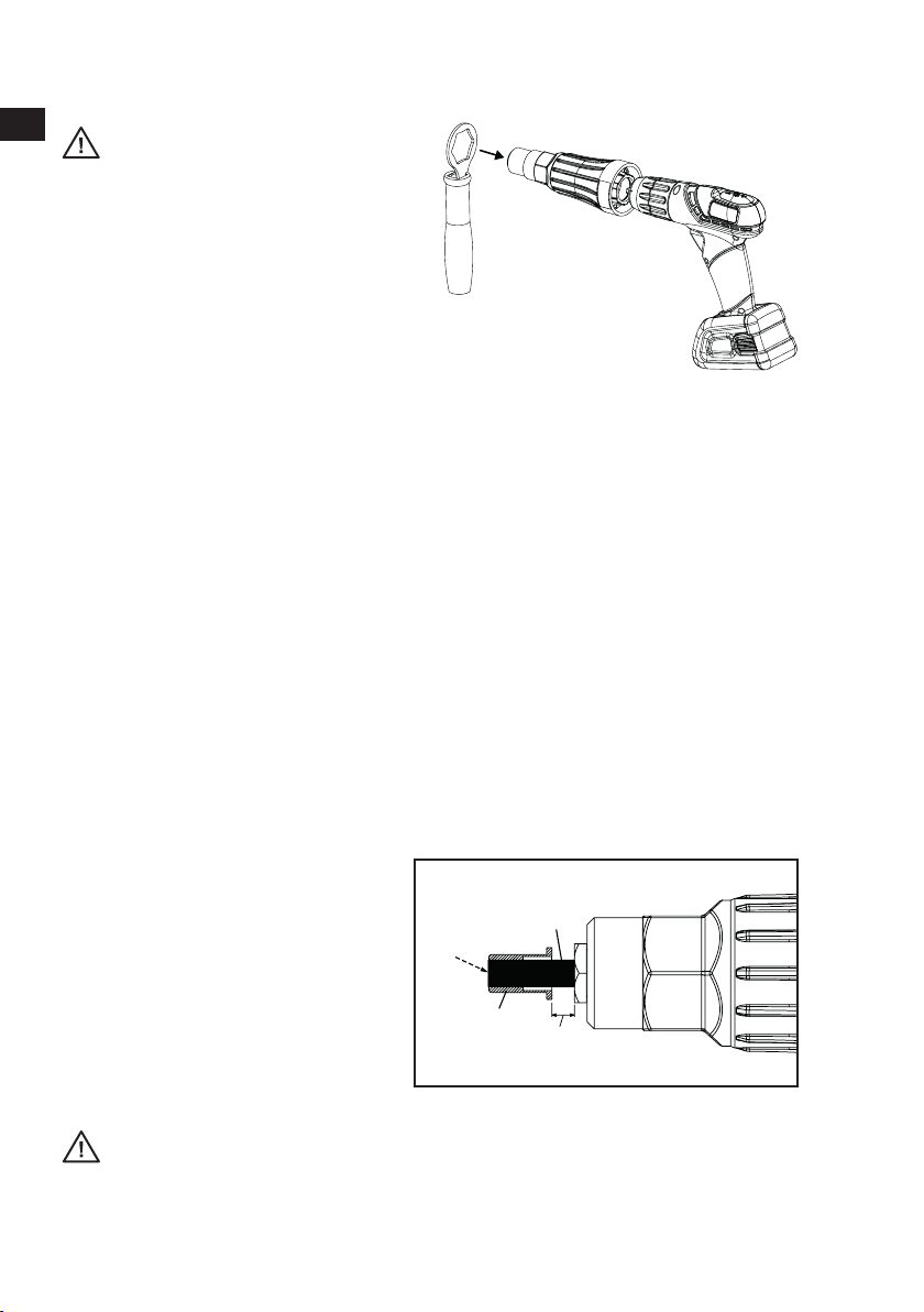
CAUTION
If the blind rivet to be used is
difficult to fasten, the counter-
rotational force will be stronger.
It is recommended to install the
Extension Handle [FIGURE 7].
And it is highly recommended to
start the power drill slowly.
FIGURE 7
7. Switch power drill to rotate in the clockwise direction.
8. Grip and hold the drill attachment firmly and then press the trigger of power drill slowly.
OPERATING INSTRUCTION: RIVET NUTS
1. Install the drill attachment to power drill.
2. Grip and hold the drill attachment firmly.
3. Switch power drill to rotate in counterclockwise direction and then press the trigger of power drill.
4. When <click, click> sound is heard, release the trigger. Then, release grip on (not holding)
the drill attachment. Mandrel should be protruding out of the drill attachment.
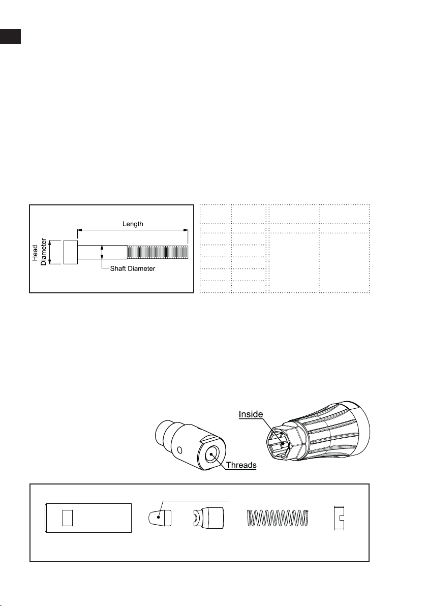
5. Switch power drill to rotate in the clockwise direction.
6. Without holding the drill attachment, press the trigger of power drill. The drill attachment
should be spinning freely. Take rivet nut and gently insert it into the Mandrel to let it screw
onto the Mandrel.
7. Release the trigger of power drill when the tip of rivet nut reaches tip of the Mandrel [Figure 8].
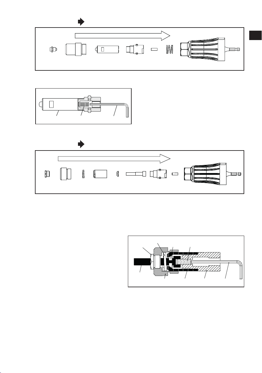
NOTE
if not using the included Mandrel or the
recommended Mandrel length, or if the
rivet nut to be used is shorter or longer
than typical rivet nuts, please leave a
clearance of 4mm – 8mm between the
end of rivet nut and the Anvil [Figure 8]
to allow the Drive Mechanism to engage
sufficiently prior to compressing rivet nut.
Not leaving enough clearance could lead
to early failure of the Drive Mechanism.
Mandrel
Rivet
Nut
Tip of
Mandrel
FIGURE 8
8. Grip and hold the drill attachment firmly and then press trigger of the power drill slowly.
CAUTION
If the rivet nut to be used is difficult to fasten, the counter-rotational force will be
stronger. It is recommended to install the Extension Handle [FIGURE 7].
And it is highly recommended to start the power drill slowly