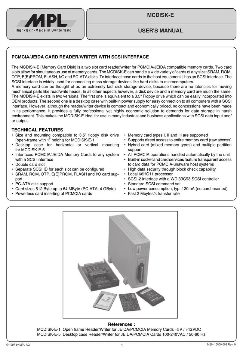
MPL MS-MCDISK-D Series User manual

© 1994 by MPL AG 1
MS-MCDISK-D Rev. B
USER'S MANUAL
High-Tech Made in Switzerland
MEH-10000-005 Rev. B
PCMCIA/JEIDA CARD READER/WRITER WITH SCSI INTERFACE
The MCDISK-D (Memory Card Disk) is a card reader/writer for PCMCIA/JEIDA compatible memory cards. MCDISK-D can
handle a wide variety of cards of any size: SRAM, ROM, OTP, E(E)PROM, FLASH and PC-ATA disks (mechanical/silicon) as
well as user specific I/O cards. To interface those cards to the host equipment MCDISK-D has an SCSI interface. The SCSI
interface is widely used for connecting mass storage devices like hard disks to microcomputers.
MCDISK-D comes in a compact desktop case. One MCDISK-D model offers a double card slot which allows for simultaneous
use of two memory cards. Memory cards and disks up to Type IV (14.2 mm thickness) can be used.
However, although the reader/writer device is economically priced, no concessions have been made in its performance. It
provides a fully professional yet highly economic solution to individual demands for data transfer and storage. This makes the
MCDISK-D ideal for use in many industrial, business and home applications with SCSI data input and/or output.
TECHNICAL FEATURES
• Desktop case with compact dimensions: 158x199x41 mm
• Interfaces PCMCIA/JEIDA Memory Cards to any system
with an SCSI interface
• Double card slot version available
• Separate SCSI ID for dual-slot versions can be configured
• SRAM, ROM, OTP, E(E)PROM, FLASH, I/O card and PC-
ATA disk support
• Card sizes 512 Byte up to 64 MByte (PC-ATA: 4 GByte)
• Memory card types I, II, III and IV are supported
• Supports direct access to entire memory card (raw access)
• Built-in socket- and card services feature transparent ac-
cess to card data for PCMCIA-unaware host systems
• High data security through block check capability
• Local 68HC11 processor
• SCSI interface with 33C93 SCSI controller
• Standard SCSI command set
• Two SCSI-2 connectors allow for SCSI bus chaining
• Switchable active SCSI termination
• UL listed
• FCC Class B compliance
• Low power consumption, typ. 150 mA (no card inserted)
• Needs external power unit, 9VAC/600mA min.
References :
MS-MCDISK-D-1 Rev. B: PCMCIA/JEIDA Reader/Writer, double PCMCIA/JEIDA (type I…IV) card slot
MS-MCDISK-D-2 Rev. B: PCMCIA/JEIDA Reader/Writer, single PCMCIA/JEIDA (type I…IV) card slot
MS-MCDISK-D-3 Rev. B: PCMCIA/JEIDA Reader/Writer, single PCMCIA/JEIDA (type I/II slot) card slot (ON REQUEST)

2
High-Tech Made in Switzerland
MS-MCDISK-D Rev. B
TABLE OF CONTENTS
INTRODUCTION ................................................................................................................................................................... 3
I. ABOUT THIS MANUAL ........................................................................................................................................... 3
II. SAFETY PRECAUTIONS AND HANDLING........................................................................................................... 3
III. RADIO AND TELEVISION INTERFERENCE........................................................................................................ 3
IV. EQUIPMENT SAFETY .......................................................................................................................................... 3
1. SPECIFICATIONS AND COMPATIBILITY ........................................................................................................................ 4
1.1 SPECIFICATIONS ................................................................................................................................................ 4
1.2 COMPATIBILITY .................................................................................................................................................. 4
1.3. PRODUCTION VERSIONS OF MCDISK-D ........................................................................................................ 4
2. SETTING UP ..................................................................................................................................................................... 5
2.1 SET-UP OVERVIEW ............................................................................................................................................ 5
2.2 REAR PANEL VIEW ............................................................................................................................................. 5
2.3 SCSI ID ................................................................................................................................................................. 5
2.4 DUAL SCSI ID FEATURE (MCDISK-D-1 ONLY) ................................................................................................. 6
2.5 TERMINATION ..................................................................................................................................................... 7
2.5.1 SCSI BUS TERMINATION ..................................................................................................................... 7
2.5.2 TERMINATOR POWER (TERMPWR) ................................................................................................... 7
2.6. PARITY ................................................................................................................................................................ 7
3. SCSI BUS AND POWER CONNECTION .......................................................................................................................... 8
3.1 SCSI BUS CONNECTION .................................................................................................................................... 8
3.2 POWER CONNECTION ....................................................................................................................................... 8
3.2.1 AC POWER UNIT .................................................................................................................................. 8
3.2.2 CONNECTING THE POWER UNIT ....................................................................................................... 9
3.2.3 ELECTRONIC FUSE .............................................................................................................................. 9
4. OPERATION .................................................................................................................................................................... 10
4.1 PCMCIA CARD TYPES ...................................................................................................................................... 10
4.2 CARD POWER CONSUMPTION ....................................................................................................................... 10
4.3 CARD HANDLING .............................................................................................................................................. 11
4.3.1 INSERTING A CARD ........................................................................................................................... 11
4.3.2 EJECTING A CARD ............................................................................................................................. 11
4.4 LED INDICATORS.............................................................................................................................................. 12
4.4.1 BASIC INDICATIONS .......................................................................................................................... 12
4.4.2 ERROR SIGNALLING .......................................................................................................................... 12
4.5 DRIVER SOFTWARE ......................................................................................................................................... 13
4.6 BATTERY REPLACEMENT ............................................................................................................................... 13
5. PHYSICAL DIMENSIONS ............................................................................................................................................... 13
DISCLAIMER ....................................................................................................................................................................... 16

3
High-Tech Made in Switzerland
MS-MCDISK-D Rev. B
INTRODUCTION
I. ABOUT THIS MANUAL
This manual assists the installation procedure by providing all
the information necessary to handle and configure the
MCDISK-D reader/writer as well as connect it to a host
system.
The MCDISK-D reader/writer is designed to work with most
host systems which are fitted with an SCSI interface. It is a
simple procedure to set up the unit, nevertheless, before
attempting any installation, please read through all applicable
sections of this manual and follow the instructions herein.
For those involved in writing drivers or special applications
that directly interface to the MCDISK-D, a Technical Refer-
ence Manual provides information required to drive the
MCDISK-D on the SCSI command level. Related closely to
this product are three more publications that supply informa-
tion about PCMCIA and SCSI interface as well as application
and card usage with the MCDISK.
• MCDISK Technical Reference Manual (supplied by MPL
AG or your local MCDISK supplier)
• MCDISK Application Note (supplied by MPL AG or your
local MCDISK supplier)
• PCMCIA PC Card Standard (July 1993, Release 2.1)
• ANSI SCSI-2 Standard (X3.131-199x, Revision 10h)
II. SAFETY PRECAUTIONS AND HANDLING
For personal safety and safe operation of the MCDISK-D,
follow all safety procedures described here and in other
sections of the manual.
WARNING: Electrical equipment may be hazard-
ous if misused.
• Handle the unit carefully, i.e. dropping or mishandling the
read/write unit can cause damage to internal assemblies.
• Keep the unit away from all sources of liquids, such as
coffee cups, drinking glasses, washing facilities etc.
• Do not expose the unit to moisture (damp, wet weather
etc.).
• For the purpose of heat dissipation, allow adequate venti-
lation to the unit by not covering it with paper or other
material.
• Use the unit always in the temperature range from
5 °C…40°C.
• Use only a power supply as defined in section 3.2.1.
• Keep this manual available for reference.
WARNING: There are no user-serviceable compo-
nents inside the MCDISK-D!
For your protection and that of your MCDISK-D disconnect the
power input immediately if any of the following conditions
exists:
• Something has been spilt onto the case.
• The unit has been damaged in any way, e.g. through
dropping.
• The unit has been exposed to excess moisture or rain.
• You suspect that the unit requires servicing or repair.
• The power input cable has been damaged.
WARNING: To disconnect power, pull the power
connector from the back of the unit (ensure that you
pull the connector, not the cord!). For this reason,
always ensure that the power input connector is
easily accessible!
III. RADIO AND TELEVISION INTERFERENCE
This equipment has been tested and found to comply with the
limits for a Class B digital device, pursuant to Part 15 of the
FCC rules. These limits are designed to provide reasonable
protection against harmful interference in a residential instal-
lation. This equipment generates, uses and can radiate radio
frequency energy and, if not installed and used in accordance
with the instructions, may cause harmful interference to radio
communications.However, there isnoguarantee that interfer-
ence will not occur in a particular installation. If this equipment
does cause harmful interference to radio or television recep-
tion, which can be determined by turning the equipment off
andon, the user isencouragedtotry to correct theinterference
by one or more of the following measures:
• Reorient or relocate the receiving antenna.
• Increase the separation between the equipment and re-
ceiver.
• Connect the equipment into an outlet on a circuit different
from that which the receiver is connected.
• Consult the dealer or an experienced radio/TV technician
for help.
Shielded cables and I/O cords must be used for this equip-
ment to comply with the relevant FCC regulations.
Changes or modifications not expressly approved in writing by
MPL AG may void the user's authority to operate this equip-
ment.
IV. EQUIPMENT SAFETY
Great care is taken by MPL that all it's products are thoroughly
and rigorously tested before leaving the factory to ensure that
they are fully operational and conform to specification. How-
ever, no matter how reliable a product, there is always the
remote possibility that a defect may occur. The occurrence of
a defect on this device may, under certain conditions, cause
a defect to occur in adjoining and/or connected equipment. It
is the users responsibility to ensure that adequate protection
for such equipment is incorporated when installing this device.
MPL accepts no responsibility whatsoever for such kind of
defects, however caused.

4
High-Tech Made in Switzerland
MS-MCDISK-D Rev. B
1. SPECIFICATIONS AND COMPATIBILITY
This chapter summarises the unit specifications, provides a
reference regarding compatibility to host systems and a table
of the various MCDISK-D models.
1.1 SPECIFICATIONS
Three MCDISK-D models are available (see table 1.3), iden-
tified by an extension: D-1, D-2 or D-3. In the table below,
model differences are indicated by this extension in parenthe-
sis.
Performance:
Transfer rate 2.5 MByte/sec
Average throughput
with SRAM card 0.9 MByte/sec
Latency 0 ms
Interfaces:
SCSI standard SCSI-2
SCSI bus connectors High density 50-pin/female
SCSI bus configuration 8-bit/single-ended
PCMCIA standard Release 2.1
PCMCIA card slots 2 (D-1)
1 (D-2, D-3)
PCMCIA card types Type I - IV (D-1, D-2)
Type I / II (D-3)
Power Requirements (without card):
9 VAC (+/- 5%) 150 mA
Requires external power unit , see section 3.2
Memory Card Current Consumption:
One card 450mA max.
Total two cards 700mA max.
Total peak 800mA, 1.5sec
Operating Environment:
Temperature 5°C ... 40°C
Relative humidity
(non-condensing) 10% ... 90%
Physical:
Height 41 mm (1.6")
Width 158 mm (6.2")
Length 199 mm (7.85")
Weight 0.60 kg (1.32 lbs)
1.2 COMPATIBILITY
MCDISK-D operates with various system platforms using
standard driver software. Some host systems do not fully
support MCDISK-D and require special driver software. MPL
AG provides a "MCDISK Application Note" where two major
subjects are reflected:
•The actual status of software and hardware support for
different host systems, including a description of the cat-
egories of use (file system, binary image transfer, SCSI
level access).
•A list of MCDISK-compatible PCMCIA cards and ATA-
disks, tested by MPL AG or MCDISK users.
1.3. PRODUCTION VERSIONS OF MCDISK-D
MCDISK- D-1 D-2 D-32
SCSI-2
connectors 2 2 2
PCMCIA
connectors 2 1 1
Read SRAM SRAM SRAM
ROM ROM ROM
FLASH FLASH FLASH
EEPROM EEPROM EEPROM
OTP OTP OTP
ATA-Disks ATA-Disks
Write SRAM SRAM SRAM
FLASH FLASH EEPROM1
EEPROM1EEPROM1
OTP1OTP1
ATA-Disks ATA-Disks
I/O access yes yes yes
Card types I, II, III, IV I, II, III, IV I, II
Table 1.3: MCDISK-D models
1Depends on card used
2This model is on request only. No support for +12V FLASH
cards

5
High-Tech Made in Switzerland
MS-MCDISK-D Rev. B
2.2 REAR PANEL VIEW
SCSI ID switch (push wheel), termination/parity switch, SCSI
connectors and AC power plug are located on the rear panel
of MCDISK-D (all models). Part descriptions in this and the
next chapter relate to these rear panel items.
Fig. 2.2: Rear panel MCDISK-D
2.3 SCSI ID
Each device on the SCSI bus must have a unique SCSI ID
number. The numbers range from 0 .. 7 which allows for a
maximum of eight SCSI devices on the bus. Before setting the
SCSI ID for MCDISK-D, an ID must be chosen that is not yet
used by other SCSI devices. Most host computer systems
already use SCSI ID 0 for the internal SCSI hard disk drive. In
principle, SCSI ID 7 is used by the host computer itself. Check
the documentation of the host computer and the attached
peripheral SCSI devices to verify the available SCSI ID
numbers.
On the MCDISK-D, the desired SCSI ID number can be
adjusted by simply pressing the push wheels +/-buttons. SCSI
ID 7 cannot be selected (host computer's own ID).
WARNING: Ensure that each SCSI device has a
unique SCSI ID number. If not, serious corruption of
data and/or failure of the host computer may result!
2. SETTING UP
This chapter (and the next one) provides all the information
required to configure the MCDISK-D reader/writer. It de-
scribes the setting of the SCSI ID, the SCSI termination
characteristics and the connection of the SCSI bus cable and
the AC power unit.
If you have any doubts on configuration, contact your
MCDISK-D supplier or an authorised dealer of your host
computer.
WARNING: Before you commence, review and
observe the safety precautions described at the
beginning of this manual to avoid personal injury or
damage to equipment.
2.1 SET-UP OVERVIEW
Set-up of MCDISK-D is a step by step procedure:
1. Remove the MCDISK-D from its cover.
2. Set the unit’s SCSI ID.
3. Terminate the SCSI bus if required. Match the SCSI parity
configuration.
4. Connect the SCSI bus cable to the unit (see chapter 3)
5. Connect the external AC power unit (see chapter 3).
6. Before starting to work with MCDISK-D, make sure that
adequate ventilation to the unit is guaranteed.
12
ON
5
+
_
SCSI ID
Pushwheel
Config. Switches:
ParityTermination
AC power plug
SCSI-2 High Density Connectors

6
High-Tech Made in Switzerland
MS-MCDISK-D Rev. B
2.4 DUAL SCSI ID FEATURE (MCDISK-D-1 ONLY)
The Dual SCSI ID feature allows to use a separate SCSI ID for
each slot on the double-slot MCDISK-D-1. This allows stand-
ard driver software (without SCSI LUN support) to be used to
access both slots. In Dual SCSI ID mode, the MCDISK-D-1
appears like two separate SCSI devices on the bus, and can
thus be handled by the host drivers as if two single-slot
MCDISKs were connected.
The Dual SCSI ID feature is disabled by default and can only
be enabled for units with firmware version V3.3 or newer. To
enable this feature, an internal jumper must be set as follows:
1. Make sure you have firmware V3.3 in your MCDISK unit. If
not, DO NOT TRY to set the jumper. Dual SCSI ID feature
will not work!
2. Use a suitable screwdriver to gently slide the four gray
plastic tabs on the top cover of the MCDISK-D-1 case
outwards.
3. Use a suitable Philips screwdriver to open the four screws.
4. Remove the top half of the MCDISK case gently. Be careful
to lift only the case, and leave the front and rear metal panel
inserted in the bottom half of the case.
5. Insert (or remove, if you want to disable the Dual SCSI ID
feature) a jumper at the position indicated by Figure 2.4
6. Make sure that you have set the right jumper.
7. Replace the top half of the case. Note that it only fits
correctly one way around.
8. Replace the screws
9. Slide the gray plastic cover tabs back until they snap in
place.
With the Dual SCSI ID feature enabled, the MCDISK-D-1 uses
two SCSI IDs on the bus: To access the lower slot, the SCSI
ID configured as described in paragraph 2.3 is used. To
access the upper slot, a second SCSI ID which is one number
higher than the SCSI ID configured is available.
The Dual SCSI ID feature is disabled when the SCSI ID is set
to 6.
For example:
•If the SCSI ID is configured as 3 and Dual SCSI ID feature
is enabled, the MCDISK-D-1 appears under SCSI ID 3 and
4 on the bus.
•If the SCSI ID is configured as 6, even if Dual SCSI ID
feature is enabled, the MCDISK-D-1 appears only under
SCSI ID 6 (as SCSI ID 7 is reserved for the host computer).
This can be used to disable the Dual SCSI ID feature
without opening the case again.
Note: The Dual SCSI ID feature works only if SCSI timeout
are strictly held as defined in the SCSI-II standard.
Some host adaptors have features like “Fast SCSI
scan”that violate the SCSI timeout periods, because
this is not relevant for many SCSI devices (including
the MCDISK with Dual SCSI ID feature disabled). If
you have SCSI problems, try disabling those “Fast
SCSI scan”features.
Note: Please refer to the MCDISK TECHNICAL REFER-
ENCE MANUAL for details about the Dual SCSI ID
feature.
J21 Pin 1-6 enables the Dual SCSI Feature
Fig. 2.4.: Dual SCSI Feature jumper J21

7
High-Tech Made in Switzerland
MS-MCDISK-D Rev. B
MCDISK
(not terminated)
Host computer
Internal SCSI device
(terminated)
External SCSI device
(terminated)
External SCSI device
(not terminated)
2.5 TERMINATION
2.5.1 SCSI BUS TERMINATION
Both ends of the SCSI bus cable must be terminated. Gener-
ally, one end is already terminated at the host computer. The
other end must be terminated by the last SCSI device on the
SCSI bus.
WARNING: Ensure that no more than two devices
on the SCSI bus are terminated. Otherwise serious
corruption of data and/or damage to the SCSI bus
devices may result!
When the MCDISK-D is the last device on the SCSI bus, it
must be terminated by setting the termination configuration
switch to the ON position (Switch No. 2). In all other cases, this
switch must be set to the OFF position!
The figure below shows an SCSI chain configuration where
the MCDISK-D is in a middle position (and therefore not
terminated).
Fig. 2.5.1: SCSI bus configuration
2.5.2 TERMINATOR POWER (TERMPWR)
Generally, the host computer is the only device on the SCSI
bus required to provide TERMPWR for the bus. Since the
MCDISK-D is a peripheral SCSI device, power for the termi-
nator networks must be supplied from the SCSI bus cable
(TERMPWR line).
The MCDISK-D contains internal components to provide
switchable Active Termination of the SCSI bus. Compared to
Passive Termination, Active Termination is far less sensitive
to TERMPWR voltage variations, which, amongst other
things, increases data security.
Figure 2.5.2 shows the terminator circuit as used on the
MCDISK-D:
Fig. 2.5.2: Active termination
Voltage
regulator
2.85V Output
110Ω
110Ω
110Ω
110Ω
18 SCSI - bus lines
TERMPWR
4.00 É5.5 V Termination
power switch
2.6. PARITY
The SCSI parity configuration of the MCDISK-D should match
that of the host computer. Check the host computer documen-
tation to verify its setting. On delivery, the MCDISK-D’s parity
is disabled (Switch No. 1 to OFF) which should be correct for
most system integrations. The parity can be enabled by
setting the parity configuration switch to the ON position.

8
High-Tech Made in Switzerland
MS-MCDISK-D Rev. B
3. SCSI BUS AND POWER CONNECTION
This paragraph provides directions for connecting the SCSI
bus cable and the power unit to the MCDISK-D.
WARNING: Before you begin, review and observe
the safety precautions described at the beginning of
this manual to avoid personal injury or damage to
equipment.
3.1 SCSI BUS CONNECTION
Two SCSI bus connectors are located at the rear of the unit.
Inside the MCDISK-D, the connectors are pin-for-pin con-
nected together and therefore allow for a simple SCSI bus
chaining.
The connectors are of the “high-density”type as described in
the SCSI-2 standard. Therefore, the MCDISK-D accepts
cables only where one cable end has a connector of the
following type: D-Sub high-density, 50-pin male (also called
DB50M mini).
Generally, the cable is not included with the MCDISK-D as the
connector at the other end of the cable is fully dependant on
the type of connector fitted on your host system or nearest
peripheral in the SCSI chain. The most commonly used
connectors for connecting to the host system are:
•Centronics 50-pin male, standard (various SCSI hosts/
peripherals)
•Centronics 50-pin male, high-density / mini (newer SCSI
hosts/peripherals)
•D-Sub 50-pin male, high-density / mini (like MCDISK-D)
•D-Sub 25-pin male, standard (all Macintosh models)
To obtain the right cable for your needs, contact your local
MCDISK dealer or an authorised dealer of your host compu-
ter.
When connecting the SCSI bus cable(s) to the MCDISK-D,
carefully align the connectors to avoid bending or damaging
the connector pins.
WARNING: The total SCSI cable length must not
exceed 6 meters (20 feet). Shielded cables and I/O
cords must be used for this equipment to comply
with the relevant FCC regulations.
3.2 POWER CONNECTION
3.2.1 AC POWER UNIT
The MCDISK-D requires an external direct plug-in AC trans-
former unit.
The input rating of this unit must correspond to the rating of
your local mains supply (e.g. 120VAC/60 Hz for USA;
230VAC/50 Hz for Europe).
The output rating of the power unit is defined by the input rating
of the MCDISK-D and must be 9VAC / 1000mA (minimum
600mA). In each case, the power unit output must be specified
to be within 9VAC ±5% at 600mA.
NOTE: This product is intended to be supplied by a
Listed Direct Plug-In Transformer Unit marked
"Class2" with output rated9V AC, minimum600 mA.
WARNING:Only a power unit with the above speci-
fications must be used. The use of any other type of
power unit may seriously damage your MCDISK!
The use of an incorrect power unit with your
MCDISK will render the warranty void!
The physical dimensions of the power connector needed for
the MCDISK-D are shown below.
Fig. 3.2.1: Physical dimensions of the power connector
The power unit is not included with the MCDISK-D due to the
wide variety of power supply ratings and AC mains connector
pin types. A power unit can be obtained from your local
MCDISK supplier or a local electronics distribution outlet.
5.5mm
2.1mm
9.5É12mm
max.
9.5mm

9
High-Tech Made in Switzerland
MS-MCDISK-D Rev. B
3.2.2 CONNECTING THE POWER UNIT
Connect the input side of your direct plug-in transformer unit
to an AC outlet. Since there is no power switch on any models
of the MCDISK-D, power is applied by inserting the power
connector of the AC power unit (output side) into the AC power
plug on the rear of the MCDISK-D.
The green LED on the front panel will light indicating that
power is applied to the MCDISK-D. The red LED will also light
indicating that there is no PCMCIA card inserted in the unit.
If the unit fails to switch on (i.e. the green LED doesn’t light)
then immediately remove the power cord! The cause could be
an internal malfunction. Refer to the next section.
3.2.3 ELECTRONIC FUSE
The MCDISK-D is protected by an electronic fuse. The fuse
protects the MCDISK-D in case of malfunction by disconnect-
ing the power input from the internal circuit. If this happens, the
green power LED will go off and will stay off as long as the fault
condition is present.
If you suspect that the fuse has opened, unplug the power
cord. Once the power source is disconnected the fuse will
connect the power input to the internal circuit again (electronic
fuse!). Wait for one minute. Then plug in the power cord again
while watching for the green power LED. If the LED just blinks
once or does not light at all, immediately unplug the power
cord and check through the procedures in the “Setting Up”
section.
If, after repeating these procedures the MCDISK-D still fails to
operate then remove the power cord and contact your local
MCDISK supplier.
The fuse does NOT need to be replaced following operation.
WARNING: There are no user serviceable parts
inside the MCDISK-D!

10
High-Tech Made in Switzerland
MS-MCDISK-D Rev. B
4. OPERATION
This chapter provides information about the use of the
PCMCIA cards and the LED indicators.
The illustration below identifies the items visible on the front
panel of the three MCDISK-D models (D-1, D-2 and D-3).
Fig. 4.1 Front panel of MCDISK-D-1
Fig. 4.2 Front panel of MCDISK-D-2
Fig. 4.3 Front panel of MCDISK-D-3
4.1 PCMCIA CARD TYPES
The MCDISK-D models have been designed to accept up to
four different PCMCIA card types:
•Type I: Thickness 3.3 mm, no raised substrate area
•Type II: Thickness 5.0 mm, 48 mm wide raised substrate
area
•Type III: Thickness 10.5 mm, 51 mm wide raised
substrate area
•Type IV: Thickness 14.2 mm, 51 mm wide raised
substrate area
Dependant on the MCDISK-D model, the usable card types
are:
MCDISK-D-1:
The lower card slot accepts all four types of cards. Due to the
front panel cut-out, the upper card slot only accepts type I - III
cards.
Type I and II cards in the lower and type I - III cards in the upper
slot can be inserted simultaneously. Type IV cards must be
inserted in the lower slot, fully occupying the space of both
slots.
MCDISK-D-2:
This single slot model accepts type I - IV cards.
MCDISK-D-3:
Only type I and II cards can be used.
4.2 CARD POWER CONSUMPTION
For heat dissipation purpose the PCMCIA card current con-
sumption has to be considered.
The current consumption of a single card must never exceed
450mA. This corresponds to a maximum power consumption
of 2.25 W with 5V technology cards.
If two cards are used simultaneously, then the total current
consumption must never exceed 700mA (e.g. 450mA for the
first card, 250mA for the second card).
The total peak current must not exceed 800mA for a maximum
period of 1.5sec, independent of one or two cards being used.
When providing power for the
WARNING: Never exceed the current ratings indi-
cated above. If exceeded, serious damage and/or
failure of the MCDISK-D may result! Note also the
specifications of your AC direct plug-in transformer
unit.
Power Status InUse
CDISK
Power Status InUse
CDISK
Power Status InUse
CDISK

11
High-Tech Made in Switzerland
MS-MCDISK-D Rev. B
4.3.2 EJECTING A CARD
To remove a card from the card slot, there is a card eject
button.
The double slot model has two eject buttons. The eject button
at the left hand side of the card slots serves the upper card slot,
the eject button on the right hand side the lower card slot.
Arrows are printed on the eject buttons that point to the card
slot they serve.
To remove the PCMCIA card push the corresponding eject
button. The card is released from the connector inside and it
may now be pulled free.
CAUTION: Do NOT attempt to pull the card free
without first pressing the card eject button!
Do NOT attempt to remove the card when the yellow
LED is lit (see also next section)!
WARNING: Avoid the situation where foreign ob-
jects, dust, liquids etc. can enter the MCDISK-D
through the card slot opening. This can cause se-
vere damage.
4.3 CARD HANDLING
Follow the instructions as described in this section when
inserting and ejecting PCMCIA cards. Refer to Figures 4.1 -
4.3 to locate indicated items.
4.3.1 INSERTING A CARD
When inserting a card into one of the card slots of the
MCDISK-D, care must be taken to ensure that the card is
inserted correctly. Follow these steps to insert the card:
1. Orientate the memory card so that the printed surface (e.g.
with manufacturer name/logo) is up and the 68-pin connec-
tor points towards the MCDISK-D card slot. Note that some
cards have an arrow indicating direction of insertion.
2. Insert the card into the slot. It should slide easily into the slot
until approx. 15 mm remain exposed and the card comes
to a soft stop. At this point gentle pressure is required to
make the final connection between the memory card and
the card slot connector.
If the card comes to a sudden stop earlier than described
above, do not press any further! Key guides on the card and
in the card slot ensure that the card cannot be fully inserted
(does not reach the connector) when inserted the wrong
way! Remove the card, check orientation and try again.
3. Whenthecard is fully inserteda small portionof thecard will
remainexposed from the cardslot opening.The redLED on
the front of the MCDISK-D will go off indicating that the card
is present. If the red LED remains lit then the card has not
been inserted correctly or cannot be operated by the
MCDISK-D (e.g. bad card type).
WARNING: Do NOT use excessive force to over-
come any resistance when inserting the card. This
should not be necessary and will severely damage
both the card and the MCDISK-D.

12
High-Tech Made in Switzerland
MS-MCDISK-D Rev. B
4.4 LED INDICATORS
The MCDISK-D is equipped with three or four LED indicators.
Refer to Figures 4.1 - 4.3 for the location of the indicators.
4.4.1 BASIC INDICATIONS
The green (leftmost) LED is the power indicator. It is lit
whenever the unit has power applied to it.
The two yellow (rightmost) LEDs are the access/lock ("InUse")
indicators for the upper and lower slot (for single slot models:
only one yellow LED). They are illuminated temporarily when-
ever an access to a memory card in any of the slots takes
place. They are illuminated permanently if the card inserted in
this slot is mounted on the host computer as a SCSI bus
volume (the card is "locked" by the host computer).
CAUTION:
Don’t eject the PCMCIA card when the yellow
LED is lit!
The red (middle) LED is the status indicator. It is illuminated
when the MCDISK-D is not operable due to one of the
following reasons:
•There is no card inserted. If a card is inserted correctly, the
red LED will go off.
•There is a card inserted, but it cannot be accessed by the
MCDISK-D. Such errors can have various causes: the unit
is attempting to write to a write-protected or read-only card,
unknown I/O card, hardware error on a memory card, etc.
During start-up (power up or SCSI bus reset), the MCDISK-D
performs some internal self tests. When everything is okay,
the red and (both) yellow indicators will flash twice simultane-
ously to indicate proper start-up and proper SCSI connection.
4.4.2 ERROR SIGNALLING
In case of an error, the red and (both) yellow indicators will
show a diagnostic status:
•The red and (both) yellow indicators remain unlit: Ensure
that the unit is connected correctly to a powered SCSI bus.
Likewise the unit cannot start-up when the SCSI bus is not
or not correctly terminated (TERMPWR O.K.?). If the SCSI
bus is O.K. and the indicators still remain unlit, there may
be a hardware problem and the unit requires service.
•The red and (both) yellow indicators flash only once and
then remain unlit: The internal RAM test has failed. The unit
requires service.
•The error LED flashes repeatedly: There is an SCSI hard-
ware problem.
•The error LED double-flashes repeatedly: This indicates a
severe SCSI bus protocol error that prevents the MCDISK-
D from continuing SCSI operation. The MCDISK-D needs
to be reset to recover from this error. If the error is perma-
nent, check SCSI cabling, terminators and SCSI ID's.
•The error LED triple-flashes repeatedly: The ROM con-
tents are not O.K. The unit requires service.
•The LEDs show some other pattern than those listed
above: There is a serious hardware problem, and the unit
needs to be returned to your local MCDISK supplier for
repair.

13
High-Tech Made in Switzerland
MS-MCDISK-D Rev. B
5. PHYSICAL DIMENSIONS
The drawing below provides the physical dimensions of the
MCDISK-D.
157.5 mm
Material : ABS (UL 94HB)
Fig. 5: Physical Dimensions MCDISK-D
4.5 DRIVER SOFTWARE
If your MCDISK supplier has provided a driver software
package with your MCDISK-D, this must be loaded on the host
computer before commencing to work with the MCDISK-D.
Follow the instructions provided with the driver and/or the
procedures laid down for installing software on the host
computer provided in the host computer documentation.
4.6 BATTERY REPLACEMENT
The MCDISK-D may contain a lithium battery which is used to
ensure that certain essential operating information stored in
the MCDISK-D is not lost when the power input to the
MCDISK-D is removed. Under normal situations the battery
should not need replacing throughout the life span of the
MCDISK-D. However if the unit has been switched off or
stored for long periods the battery may become discharged.
The battery MUST only be replaced by qualified service
personnel of MPL or its authorised dealers and agents.
There are no user serviceable parts inside the MCDISK.
Opening the MCDISK-D will render the warranty void.
The battery inside the MCDISK-D is NOT rechargeable.
WARNING: Danger of explosion if battery is re-
charged or incorrectly replaced. Replacement only
to be undertaken by qualified service personnel.
Replace only with the same or equivalent type recommended
by the manufacturer. Dispose of used batteries in accordance
with the manufacturer’s instructions.

14
High-Tech Made in Switzerland
MS-MCDISK-D Rev. B
This page is intentionally left blank

15
High-Tech Made in Switzerland
MS-MCDISK-D Rev. B
This page is intentionally left blank

Printed in Switzerland
Our local distributor:
1294 16
High-Tech Made in Switzerland
MS-MCDISK-D Rev. B
COPYRIGHT AND REVISION HISTORY
Copyright © 1994 by MPL AG Elektronikunternehmen. All
Rights Reserved. Reproduction of this document in part or
whole, by any means is prohibited, without written permission
from MPL AG Elektronikunternehmen.
This manual reflects the revision B of the MCDISK-D and
firmware revision 3.3.
Publication Date : August 1995
DISCLAIMER
All implied warranties on the product and manuals, including
implied warranties of merchantability and fitness for a particu-
lar purpose, are limited in duration to twelve (12) months from
the date of the original retail purchase of this product.
MPL has fully tested the MCDISK and reviewed the documen-
tation. However, MPL makes no warranty or representation,
either expressed, or implied, with respect to this product, its
quality, performance, merchantability, or fitness for a particu-
lar purpose.
In no event will MPL be liable for direct, indirect, special,
incidental, or consequential damages resulting from any de-
fect in the product or its documentation, even if advised of the
possibility of such damages. In particular MPL shall have no
liability for any programs or data stored in or used with this
product, including the costs of recovering such programs or
data.
MPL AG reserves the right to make changes to any product
herein to improve reliability, function or design.
AUTHOR'S NOTE
Dear user of this product. It is my expressed wish that this
product is not to be used to apply any kind of violence to
anyone. Because there is no absolute criterium for violence,
I trust your subjective interpretation –if it’s honest for you, it’s
OK for me.
Disregarding my wish will not break the license agreement or
any other contracts. However, ignoring it would mean not
respecting the thoughts I had when putting my efforts into this
product.
L. Zeller, MPL AG
MCDISK is a trademark of MPL AG Elektronikunternehmen.
This manual suits for next models
3
Table of contents
Other MPL Card Reader manuals
Popular Card Reader manuals by other brands
Logic Controls
Logic Controls MR3000 Specifications

UTC Fire and Security
UTC Fire and Security interlogix AL-1191 Programming manual
Dazzle
Dazzle 6 In 1 Reader user manual

Salto
Salto WRD0B installation guide
Addonics Technologies
Addonics Technologies AEPDDESUWP-X specification
aqprox!
aqprox! DNIe user guide
