urmet domus 1068 User manual

DS1068-002B LBT20542
PROXIMITY READER
WITH SIMON URMET ADAPTER
LECTEUR DE PROXIMITÉ
AVEC ADAPTATEUR SIMON URMET
NÄHERUNGSLESEGERÄT
MIT ADAPTER SIMON URMET
Ref. 1068/435-/436
Through the following QR Code, it is possible to download the eventual new version of the booklet in
English, French and German language:
Mod.
1068
Réf. 1068/435-/436 Ref. 1068/435-/436
N. 1 Lecteur transpondeur N. 1 Transponder reader
N. 3 étiquettes adhésives zones N. 3 zone adhesive labels
N. 1 Adaptateur Simon Urmet nea N. 1 Simon Urmet nea adapter
Ref. 1068/435-/436
N. 1 Transponder-Lesegerät
N. 3 Aufklebeschilder Bereiche
N. 1 Adapter Simon Urmet nea
1068/435
http://qrcode.urmet.com/default.aspx?prodUrmet=141755&lingua=en
http://qrcode.urmet.com/default.aspx?prodUrmet=145607&lingua=en
1068/436

2 DS1068-002B
ENGLISH
GENERAL DESCRIPTION
The device is provided with:
4 indicator LEDs: 3 for system status and 1 for the alarm memory
2 alarm inputs
Available in the following colors:
1068/435: black front
1068/436: white front
The reader can be installed on Bticino Magic frames and on Bticino TT MATIX frames using the Bticino
adapter code A5374/1. The adapter is provided to allow installing the reader on Simon Urmet nea frames.
The reader may be inserted as point in the following wiring systems using optional adapter frames: Bticino
Living, Bticino Living Light / Bticino International / Gewiss Playbus / Vimar Idea / Vimar Plana (Ref.
1056/337), Bticino Axolute (Ref. 1033/036), Vimar Eikon (Ref. 1033/038). The reader is powered by the
bus, which connects it to the control panel and is configured by programming.
WARNING! This document provides only some essential product information.
Refer to 1067 and 1068 series control panel manuals for more detailed information.
The transponder readers can read transponder keys Ref. 1068/432.
The reader is provided with 4 LEDs for indicating system state and zones arming state.
OPERATION
GREEN LED
The following states are assumed:
Off:
The zones are off
On:
The zones are armed
Blinking:
Key not recognised
YELLOW LED
It assumes the following states:
On fixed:
Alarm stored or fault present
Blinking:
Presence of at least one open input in the system
Fast Blinking:
Key present

DS1068-002B 3
TOTAL ARMING AND DISARMING
Approach the key to approximately 1 cm from the proximity reader and move it away when the yellow LED
blinks. The 3 green LEDs indicate the state of the monitored zones: LED on corresponds to zone active. If
multiple zones are associated with a LED, the LED will blink when they are not all armed. The possibility of
activation of each zone depends on the programming of the reader and the key used.
PARTIAL ARMING
Approach the key to approximately 1 cm from the proximity reader, hold it in the position for at least 3
seconds and move it away when the green LEDs blink. The reader will show the various partial arming
combinations starting from the last one after a few instants. To confirm the choice hold the Key. The LEDs
indicate the armed zones.
NOTE: If you use a key is not acquired (key not recognized), the green LED will blink rapidly.
INSTALLATION
The reader can be installed on Bticino Magic frames using the adapter provided on Simon Urmet nea
frames. Optional adapter frames for other wiring systems are available.
NOTE: Multiple readers can be installed side by side providing their address number is sequential (reader
1, reader 2, etc.
CONNECTIONS
A 4-wire bus is used to connect to the control panel.
The total length of all bus stretches must not exceed 400 m.
Wires with cross-section area of 0.5 mm2or larger must comply with IEC 60332-1-2; wires with
crosssection area smaller than 0.5 mm2must comply with IEC 60332-2-2.
ALARM INPUTS
The device has two freely programmable alarm inputs.
The two inputs are provided closed with two different colour wires as standard.
The yellow wire identifies input 1, the green wire identifies input 2.
Connect the tamper of input 1 of the reader (yellow wire: cut the wire and
connect the two pieces to the tamper). TAMPER is the default factory setting.
Connect another device, if required, to input 2 (green wire: cut the wire and
connect the two pieces to the device).

4 DS1068-002B
For connections, interrupt the loop and use the same wires to connect to the detector.
Inputs may be programmed as NC, NO, single balance and double balance. Both inputs can manage fast
signals from seismic or roller blink sensors. Connection mode is NC type fixed in this case.
WARNING! “Double balance” is the only EN50131 compliant connection mode. Refer to the manuals of
1067 and 1068 series control units for further, more detailed information.
DEVICE ACQUISITION
The reader can be acquired by pressing the dedicate button.
For details on the acquisition procedure, refer to the control panel installation
manual.
To display the reader address, press the button and count the blink of the yellow
LED.
KEY CUSTOMISATION
Key customisation may be useful, for example, to associate a key with limited operation. The key can be
rapidly identified by inserting the coloured bulbs provided in the seats on the key.
TECHNICAL SPECIFICATIONS
Rated supply voltage (picked by the control panel through the communication bus)........................13.8 V⎓
Operating voltage min/max....................................................................................................9 V⎓÷ 15 V⎓
Rated current absorption at 13.8 V⎓:
LEDs OFF .....................................................................................................................................33 mA
All LEDs ON ..................................................................................................................................36 mA
Auxiliary inputs ...........................................................................................................................................2
Degree of protection of casing.....................................................................................................IP40 / IK02
Operating temperature............................................................................................................. -10°C ÷ 40°C
Dimensions (W x H x D) .....................................................................................................50 x 40 x 22 mm
Symbol
Description
⎓
Direct input voltage.
See the installation manual of the device.
EN50131

DS1068-002B 5
FRANÇAIS
DESCRIPTION GÉNÉRALE
Le dispositif est équipé de :
4 LED de signalisation : 3 pour l’état du système et 1 pour la mémoire d’alarme
2 entrées d'alarme
Disponible dans les couleurs suivantes :
1068/435: façade noir
1068/436: façade blanche
Le lecteur est compatible avec l’installation sur les cadres Bticino Magic et, au moyen de l’adaptateur
Bticino code A5374/1, sur les cadres Bticino TT MATIX. L’adaptateur fourni avec le produit permet d'installer
le lecteur sur les cadres Simon Urmet nea. Grâce aux cadres adaptateurs optionnels, le lecteur peut être
inséré en tant que connecteur à l’intérieur des lignes civiles suivantes : Bticino Living, Bticino Living Light /
Bticino International / Gewiss Playbus / Vimar Idea / Vimar Plana (Réf. 1056/337), Bticino Axolute (Réf.
1033/036), Vimar Eikon (Réf. 1033/038). Le lecteur est alimenté par le Bus qui le connecte à la centrale, et
il peut être configuré par la programmation.
ATTENTION ! Dans ce document ne sont reportées que quelques indications essentielles sur le produit.
Pour obtenir d’autres informations détaillées, consulter les manuels des centrales des séries
1067 et 1068.
Les lecteurs transpondeur sont des dispositifs en mesure de lire les clés à transpondeur Réf. 1068/432.
Le lecteur est équipé de 4 LED pour la signalisation de l'état de l'installation et de l'état d'activation des zones.
LED VERTES
Prennent les états suivants :
Éteintes :
Les zones sont désactivées
Allumées :
Les zones sont activées
Clignotantes :
Clés non reconnue
LED JAUNES
Prennent les états suivants :
Allumées fixes :
Alarme mémorisée ou panne présente
Clignotantes :
Présence d'au moins une entrée ouverte dans
l'installation
Clignotantes rapides:
Clé présente

6 DS1068-002B
FONCTIONNEMENT
M.E.S ET M.H.S. TOTALE
Rapprocher la clé de 1 cm environ du lecteur de proximité et l'éloigner quand la LED jaune clignote.
Les 3 LED vertes indiquent l'état des zones contrôlés : la LED allumée correspond à la zone activée. Si
plusieurs zones sont associées à une LED, lorsque ceux-ci ne sont pas tous activés, la LED clignote. La
possibilité d’activation de chaque zone est subordonnée de la programmation du lecteur et de la clé utilisée.
MISE EN SERVICE PARTIELLE
Rapprocher la clé de 1 cm environ du lecteur de proximité, la garder en position pendant au moins 3
secondes et l'éloigner quand les LED vertes clignotent. Après quelques instants, le lecteur présente les
possibles combinaisons de segmentation, à partir de la dernière effectuée. Pour confirmer le choix
approcher la clé : les LED des zones activées ils s’allument.
REMARQUE : Si on utilise une clé pas acquis (clé pas reconnue), les LED vert clignote rapidement.
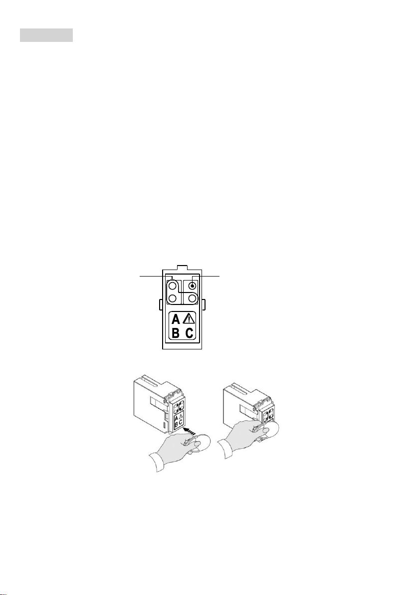
INSTALLATION
Le lecteur est compatible avec l’installation sur les cadres Bticino Magic et, au moyen de l’adaptateur
fourni, sur les cadres Simon Urmet nea. Des cadres adaptateurs optionnels pour d'autres lignes civiles
sont également disponibles.
REMARQUE : Il est possible de juxtaposer plusieurs lecteurs à condition que leur numéro d'adresse est
séquentiel (lecteur n. 1, lecteur n. 2, etc.).
RACCORDEMENTS
Le raccordement avec la centrale a lieu sur le BUS à 4 conducteurs.
La longueur totale de tous les segments BUS ne doit pas dépasser 400 m.
Les câbles utilisés doivent satisfaire la norme IEC 60332-1-2 si la section mesure au moins 0,5 mm2,
ou la norme IEC 60332-2-2 si la section mesure moins de 0,5 mm2.

DS1068-002B 7
ENTREES D'ALARME
Le dispositif présente 2 entrées d'alarme pouvant être programmées librement.
Les entrées sont fournies fermées de série avec deux conducteurs de couleur
différente. Le fil jaune identifie l’entrée 1, alors que le fil vert identifie l’entrée 2.
Relier le tamper à l’entrée 1 du lecteur (fil jaune : interrompre le fil, en le
coupant, et connecter les deux tronçons au tamper). L’entrée sort de l’usine déjà
programmée pour SABOTAGE.
Relier un autre dispositif éventuel à l'entrée 2 (fil vert : interrompre le fil, en le
coupant et connecter les deux tronçons au dispositif).
Pour les raccordements, interrompre le loop est utiliser les mêmes fils pour le raccordement au détecteur.
Les entrées peuvent être programmées en tant que NF, NO, Simple équilibrage et Double équilibrage. Les
deux entrées peuvent gérer les signaux rapides en provenance des détecteurs sismiques ou des volets ;
dans ce cas, le mode de raccordement est fixe de type NF.
ATTENTION ! La seule modalité de raccordement conforme à la norme EN50131 est celle à “Double
Equilibrage”. Pour plus d’informations, se reporter aux manuels des centrales des séries 1067 et 1068.
ACQUISITION DE DISPOSITIF
Activer le lecteur en appuyant sur le bouton.
Pour plus de détails sur la procédure d'acquisition, reportez-vous au manuel
d'installation de la centrale.
Pour voir le numéro du lecteur, appuyer
sur le bouton
et compter le numéro de
clignotement de la LED jaune.
PERSONNALISATION DES CLES
La personnalisation des clés peut être utile, par exemple, quand il faut associer une opérativité limitée à
une clé. En introduisant les boutons colorés (fournis avec le produit) dans les sièges prévus sur la clé, il est
possible de rapidement identifier la clé concernée.
EN50131

8 DS1068-002B
CARACTERISTIQUES TECHNIQUES
Tension nominale d’alimentation (prélevés de la centrale par bus de communication).....................13,8 V⎓
Tension de fonctionnement min/max .....................................................................................9 V⎓÷ 15 V⎓
Courant nominal absorbé à 13,8 V⎓:
LED éteintes..................................................................................................................................33 mA
LED toutes allumées......................................................................................................................36 mA
Entrées auxiliaires......................................................................................................................................2
Degré de protection du boîtier .....................................................................................................IP40 / IK02
Température de fonctionnement.............................................................................................. -10°C ÷ 40°C
Dimensions (L x H x P) ......................................................................................................50 x 40 x 22 mm
Symbole
Explication
⎓
Tension d’alimentation continue.
Se reporter au manuel d’installation du dispositif.

DS1068-002B 9
DEUTSCH
ALLGEMEINE BESCHREIBUNG
Das Gerät ist ausgerüstet mit:
4 Melde-LEDs: 3 für den Systemstatus und 1 für den Alarmspeicher
2 Alarm Eingänge
Erhältlich in den folgenden Farben:
1068/435: schwarze Fronttafel
1068/436: weiße Fronttafel
Das Lesegerät eignet sich für eine Installation auf den Rahmen Bticino Magic sowie mittels des Bticino-
Adapters Art.-Nr. A5374/1 auf den Rahmen Bticino TT MATIX. Der mitgelieferte Adapter ermöglicht das
Installieren des Lesegeräts auf den Rahmen Simon Urmet nea. Durch Kann das Lesegerät anhand der
optionalen Adapter Rahmen als Schalterdose in das Innere der folgenden zivil genutzten Linien eingesetzt
werden: Bticino Living, Bticino Living Light / Bticino International / Gewiss Playbus / Vimar Idea / Vimar
Plana (Ref. 1056/337), Bticino Axolute (Ref. 1033/036), Vimar Eikon (Ref. 1033/038). Das Lesegerät wird
über die Busverbindung zur Zentrale mit Strom versorgt und mittels Programmierung konfiguriert.
ACHTUNG! In diesem Dokument werden nur einige wesentliche Angaben zum Produkt wiedergegeben.
Für weitere und detaillierte Informationen beziehen sie sich auf die Anleitungen der Serien 1067 und
1068 zentralen.
Die Lesegeräte für Transponder sind Vorrichtungen zum Lesen der Transponderschlüssel Typ 1068/432.
Das Lesegerät ist mit 4 LEDs ausgestattet, die den Anlagenstatus und den Aktivierungsstatus der Bereiche
signalisieren.
GRÜNE LEDS
NehmendiefolgendenStatusan:
Ausgeschalte:
Die Bereiche sind deaktiviert
Eingschaltet:
Die Bereiche sind aktiviert
Blinklicht:
Schlüssel nicht erkannt
GELBE LED
Nimmt die folgenden Status an:
Mit Dauerlicht eingeschaltet:
Alarm gespeichert oder Defekt vorhanden
Blinklicht:
zumindest ein offener Eingang in der Anlage vorhanden
Schnelles Blinklicht:
Schlüssel vorhanden

10 DS1068-002B
FUNKTIONSWEISE
GESAMTAKTIVIERUNG UND GESAMTDEAKTIVIERUNG
Den Schlüssel bis auf etwa 1 cm an das Näherungslesegerät heranführen und diesen wieder wegbewegen,
wenn die gelbe LED blinkt. Die 3 grünen LEDs zeigen den Status der kontrollierten Bereiche an: eine
eingeschaltete LED entspricht einer aktivierten Bereiche. Wenn einer LED mehrere Bereiche zugeordnet sind,
blinkt diese LED, wenn nicht alle Bereiche aktiviert sind. Die Aktivierungsmöglichkeit einer jeden Bereich hängt
von der Programmierung des Lesegeräts und dem verwendeten Schlüssel ab.
TEILAKTIVIERUNG
Den Schlüssel bis auf etwa 1 cm an das Näherungslesegerät heranführen, mindestens 3 Sekunden lang in
dieser Position halten und diesen dann wieder wegbewegen, wenn die grünen LEDs blinken. Nach einigen
Sekunden gibt das Lesegerät die möglichen Kombinationen für eine Partialisierung, beginnend bei der
zuletzt durchgeführten, an. Zum Bestätigen der Auswahl den Schlüssel heranführen: die LEDs der
aktivierten Bereiche schalten sich ein.
HINWEIS: Wenn ein nicht erfasster Schlüssel (nicht erkannter Schlüssel) verwendet wird, blinken die
grünen LEDs schnell.
INSTALLATION
Das Lesegerät eignet sich für eine Installation auf den Rahmen Bticino Magic sowie mittels im Lieferumfang
enthaltenen Adapters auf den Rahmen Simon Urmet nea. Für andere zivil genutzte Linien sind optionale
Adapter für Rahmen erhältlich.
HINWEIS: Es können mehrere Lesegeräte nebeneinander angeordnet werden, sofern sie eine
sequentielle Adressennummer aufweisen (Lesegerät Nr. 1, Lesegerät Nr. 2, usw.)

DS1068-002B 11
VERBINDUNGEN
Die Verbindung zur Zentrale wird über einen 4-Leiter-BUS hergestellt.
Die Gesamtlänge aller BUS-Abschnitte darf nicht mehr als 400 m betragen.
Die verwendeten Kabel müssen bei einem Querschnitt von 0,5 mm2oder mehr der Norm IEC 60332-
1-2 entsprechen bzw. der Norm IEC 60332-2-2 bei einem Querschnitt von unter 0,5 mm2.
ALARMEINGÄNGE
Das Gerät weist 2 frei programmierbare Eingänge auf. Serienmäßig werden die
beiden Eingänge geschlossen mit zwei verschiedenfarbigen Leitern geliefert.
Der gelbe Draht identifiziert den Eingang 1, der grüne Draht den Eingang 2.
Den Sabotageschutz am Eingang 1 des Lesegeräts anschließen (gelber Draht:
den Draht unterbrechen, indem man ihn durchschneidet und die beiden
Endstücke mit dem Sabotageschutz verbinden). Beim Verlassen des Werks ist
der Eingang bereits auf MANIPULATION programmiert. Eine eventuelle weitere
Vorrichtung am Eingang 2 anschließen (grüner Draht: den Draht unterbrechen,
indem man ihn durchschneidet und die beiden Endstücke mit der Vorrichtung
verbinden).
Für die Anschlüsse den Regelkreis unterbrechen und die gleichen Drähte für den Anschluss an den Sensor
verwenden.
Die Eingänge können als NC, NO, einfachsymmetrischer oder doppelsymmetrischer Eingang programmiert
sein. Beide Eingänge können schnelle Signale steuern, die von den seismischen Sensoren oder Rollläden
eingehen; in diesem Fall ist NC als Verbindungsmodus fest vorgegeben.
ACHTUNG! Die einzige der Norm EN50131 entsprechende Verbindungsform ist jene mit
“doppelsymmetrischem Signal”. Für weitere und detaillierte Informationen beziehen sie sich auf die
Anleitungen der Serien 1067 und 1068 zentralen.
EN50131

12 DS1068-002B
ERFASSUNG DES GERÄTES
Das Lesegerät durch Drücken der entsprechenden Taste erfassen.
Für nähere Angaben zum Erfassungsvorgang wird auf das
Installationshandbuch der Zentrale verwiesen.
Um die Nummer des Lesegeräts anzuzeigen, die Taste drücken und die Anzahl
der Blinkaktionen der gelben LED zählen.
PERSONALISIERUNG DER SCHLÜSSEL
Die Personalisierung der Schlüssel kann beispielsweise dann von Nutzen sein, wenn man einem Schlüssel
eine begrenzte Funktionsfähigkeit zuweisen möchte. Durch Anbringen der im Lieferumfang enthaltenen
farbigen Kennzeichnungen in den auf dem Schlüssel vorgesehenen Sitzen kann dieser Schlüssel schnell
erkannt werden.
TECHNISCHE MERKMALE
Versorgungsnennspannung (über Kommunikationsbus aus der Zentrale kommend).......................13,8 V⎓
Betriebsspannung min/max ...................................................................................................9 V⎓÷ 15 V⎓
Bei 13,8 V⎓absorbierter Nennstrom:
LEDs ausgeschaltet.......................................................................................................................33 mA
Alle LEDs ausgeschaltet................................................................................................................36 mA
Hilfseingänge..............................................................................................................................................2
Gehäuseschutzart .......................................................................................................................IP40 / IK02
Betriebstemperatur.................................................................................................................. -10°C ÷ 40°C
Abmessungen (HxBxT).......................................................................................................50 x 40 x 22 mm
Symbol
Erklärung
⎓
Gleichstrom-Spannungsversorgung.
Siehe Installationsanleitung des Geräts.

DS1068-002B 13
ENGLISH
DIRECTIVE 2012/19/EU OF THE EUROPEAN PARLIAMENT AND OF THE COUNCIL of 4 July
2012 on waste electrical and electronic equipment (WEEE)
The symbol of the crossed-out wheeled bin on the product or on its packaging indicates that this
product must not be disposed of with your other household waste. Instead, it is your responsibility to
dispose of your waste
equipment by handing it over to a designated collection point for the recycling of waste electrical and
electronic equipment.
The separate collection and recycling of your waste equipment at the time of disposal will help to conserve
natural resources and ensure that it is recycled in a manner that protects human health and the
environment.
For more information about where you can drop off your waste equipment for recycling, please contact your
local city office, your household waste disposal service or the shop where you purchased the product.
FRANÇAIS
DIRECTIVE EUROPEENNE 2012/19/UE du 4 juillet 2012 relatif aux déchets d'équipements
électriques et électroniques (DEEE)
Le symbole de la poubelle sur roues barrée d'une croix présent sur le produit ou sur son
emballage indique que ce produit ne doit pas être éliminé avec vos autres déchets ménagers.
Au lieu de cela, il est de votre responsabilité de vous débarrasser de vos équipements usagés en les
remettant à un point de collecte spécialisé pour le recyclage des déchets des équipements électriques et
électroniques (DEEE). La collecte et le recyclage séparés de vos équipements usagés au moment de leur
mise au rebut aidera à conserver les ressources naturelles et à assurer qu'elles sont recyclées d'une
manière qui protège la santé humaine et l'environnement.
Pour plus d'informations sur les lieux de collecte où vous pouvez déposer vos équipements usagés pour le
recyclage, veuillez contacter votre revendeur, votre service local d'élimination des ordures ménagères.
DEUTSCH
RICHTLINIE 2012/19/EU DES EUROPÄISCHEN PARLAMENTS UND DES RATES VOM 4.
Juli 2012 über Elektro- und Elektronik-Altgeräte (WEEE)
Das Symbol der durchgestrichenen Abfalltonne auf Rädern auf dem Produkt oder dessen
Verpackung gibt an, dass das Produkt nicht zusammen mit dem Hausmüll entsorgt werden darf.
Es liegt daher in Ihrer Verantwortung, Ihre Altgeräte zu entsorgen, indem Sie diese bei einer geeigneten
Sammelstelle für das Recycling für Elektro- und Elektronik-Altgeräte abgeben.
Die getrennte Sammlung und das Recycling Ihrer Altgeräte bei der Entsorgung tragen zur Erhaltung
natürlicher Ressourcen bei und garantieren, dass diese auf gesundheits- und umweltverträgliche Weise
recycelt werden.
Weitere Informationen dazu, wo Sie Ihre Altgeräte zum Recycling abgeben können, erhalten Sie bei Ihrer
Gemeindeverwaltung, Ihrem Hausmüll-Entsorgungsdienst oder bei dem Händler, bei dem Sie das Produkt
gekauft haben.

14 DS1068-002B
ENGLISH
SIMPLIFIED EU DECLARATION OF CONFORMITY
Hereby, Urmet S.p.A. declares that the radio equipment type:
Proximity reader Ref. 1068/435 and Ref. 1068/436 are in compliance with Directive 2014/53/EU.
The full text of the EU declaration of conformity is available at the following internet address:
www.urmet.com
FRANÇAIS
DECLARATION UE DE CONFORMITE SIMPLIFIEE
Le soussigné, Urmet S.p.A., déclare que l’équipement radioélectrique du type
Lecteur de proximité Réf. 1068/435 et Réf. 1068/436 sont conformes à la directive 2014/53/UE.
Le texte complet de la déclaration UE de conformité est disponible à l'adresse internet suivante :
www.urmet.com
DEUTSCH
VEREINFACHTE EU-KONFORMITÄTSERKLÄRUNG
Hiermit erklärt Urmet S.p.A, dass die Funkanlagentypen
Näherungslesegerät Modell 1068/435 und Modell 1068/436 der Richtlinie 2014/53/EU entsprechen.
Der vollständige Text der EU-Konformitätserklärung ist unter der folgenden Internetadresse verfügbar:
www.urmet.com

DS1068-002B 15

16 DS1068-002B
LBT20542
DS1068-002B
Area tecnica
servizio clienti +39. 011.23.39.810
http://www.urmet.com
e-mail: info@urmet.com
MADE IN ITALY
URMET S.p.A.
10154 TORINO (ITALY)
VIA BOLOGNA 188/C
Telef. +39. 011.24.00.000 (RIC.AUT.)
Fax +39. 011.24.00.300 - 323
Other manuals for 1068
9
This manual suits for next models
2
Table of contents
Languages:
Other urmet domus Card Reader manuals
Popular Card Reader manuals by other brands

Kingston Technology
Kingston Technology MobileLite Wireless G3 user manual

Magtek
Magtek cDynamo Quick installation guide

Rosslare
Rosslare AYC-F60 Series Installation and programming manual

Deister electronic
Deister electronic RDL150 RS485 Wiring and installation instruction

VeriFone
VeriFone UX302 installation guide

Magtek
Magtek cDynamo Quick installation guide