MPL PIP4x User manual
PACKED INDUSTRIAL PC with 8th and 9th Generation INTEL CORE and XEON E
Processor amilies
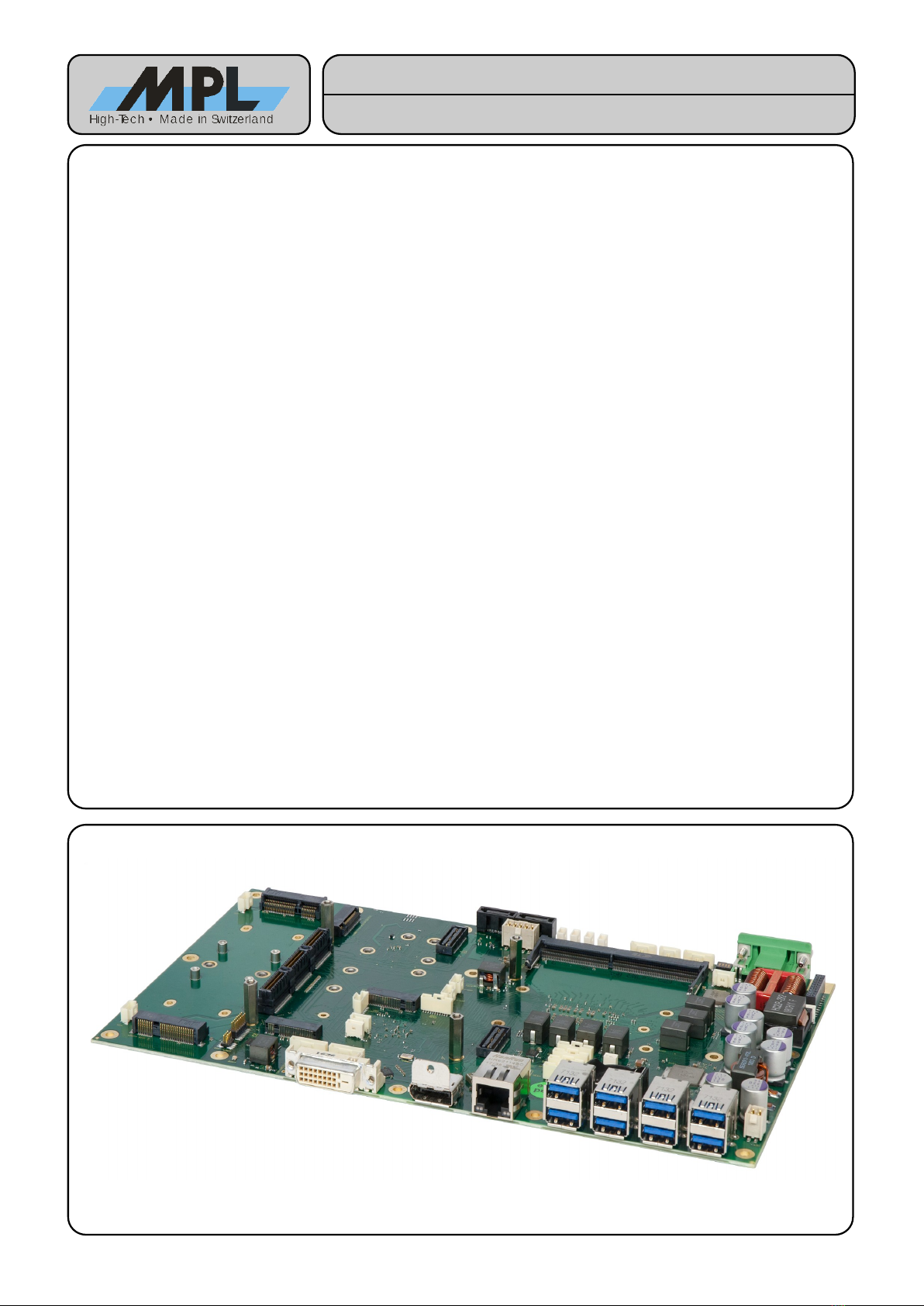
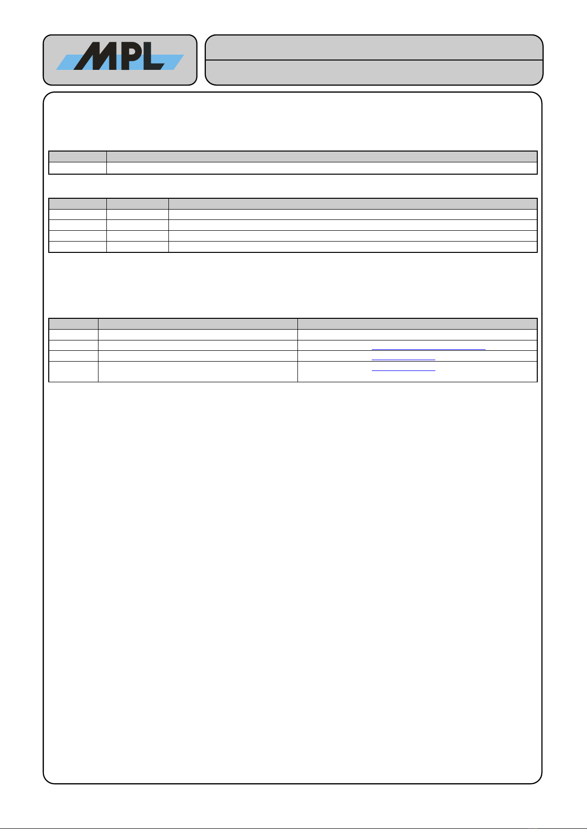
The PIP4x is a low power, high performance and rugged industrial embedded computer. It can be operated in
standard or even in harsh environment. The PIP4x has been designed for 24/7 operation and uses extended
lifec cle series processors. It can be used for an PC application where a complete solution is needed. The
Open-Frame variant is particularl suitable during the customer evaluation phase or for seamless integration
into customers project. The PIP4x offers up to 3 displa s simultaneousl , USB and legac I/O, NVMe mass
storage, PCI Express x16 (Gen3), ECC protected s stem memor , TPM 2.0 and Intel AMT support.
Furthermore, various extensions can be provided, such as MXM graphic cards, serial buses and even
customized circuits. The PIP4x has the option to be batter powered to prevent power failures in safet -relevant
environments or working as a mobile device.
eatures:
●8th and 9th Gen. Intel Coffee Lake H & HR SKU
●25W and 45W CPU (cTDP, Configurable TDP)
●Intel HD Graphics 630
●Up to 64 GB DDR4 ECC RAM
●CM246 Chipset
●TPM2.0
●iAMT12
●1x Gigabit Ethernet
●Displa port & DVI-D
●8x USB 3.1 Ports and 4x USB2.0 Header
●4x RS-232 or RS-485 Isolated (optional)
●PCIe/104
●m.2 Ke -A (PCIe / USB2.0)
●m.2 Ke -B (USB3.0 / SATA / PCIe / Dual SIM)
●m.2 Ke -M (NVMe x4 / SATA)
●2x mPCIe/mSATA (SIM Card Header)
●2x SATA Ports
●HW Watchdog
●Intel HD Audio, SD-Card, SPI and I2C Header
●PCIe and Displa Header (eDP)
●Load Dump and Reverse Polarit Protection
●Ignition and Power Button Input
2023 b MPL AG 1 MEH-1088-001 Rev. D
PIP4x
User Manual

TABLE O CONTENTS
1 INTRODUCTION............................................................................................................5
1.1 ABOUT THIS MANUAL........................................................................................................5
1.2 SA ETY PRECAUTIONS AND HANDLING.........................................................................5
1.3 ELECTROSTATIC DISCHARGE (ESD) PROTECTION.......................................................5
1.4 EQUIPMENT SA ETY..........................................................................................................5
1.5 MANUAL REVISIONS...........................................................................................................6
1.5.1 RELATED PRODUCTS.................................................................................................6
1.5.2 REVISION HISTORY....................................................................................................6
1.6 RELATED DOCUMENTATION.............................................................................................6
1.7 ORDERING IN ORMATION.................................................................................................7
1.7.1 Mainboards.................................................................................................................... 7
1.7.2 Housing Options............................................................................................................ 8
2 SPECI ICATION............................................................................................................9
2.1 ELECTRICAL........................................................................................................................ 9
2.1.1 Processor...................................................................................................................... 9
2.1.2 BIOS.............................................................................................................................. 9
2.1.3 Memor .......................................................................................................................... 9
2.1.4 Graphics........................................................................................................................ 9
2.1.5 Mass Storage................................................................................................................ 9
2.1.6 Intel AMT (onl supported b XEON and i7)..................................................................9
2.1.7 EC (Embedded Controller)............................................................................................9
2.1.8 Ethernet....................................................................................................................... 10
2.1.9 Indicators..................................................................................................................... 10
2.1.10 TPM 2.0..................................................................................................................... 10
2.1.11 Ignition and Power Button Signal...............................................................................10
2.1.12 Serial Ports (Optional Modules).................................................................................10
2.1.13 Interfaces................................................................................................................... 10
2.2 PHYSICAL.......................................................................................................................... 11
2.3 POWER............................................................................................................................... 12
2.3.1 POWER INPUT........................................................................................................... 12
2.3.2 Internal 12V Buck-Boost Converter (Peripheral Power, CPU, Chipset).......................12
2.3.3 POWER DISSIPATION............................................................................................... 12
2.4 ENVIRONMENTAL CONDITIONS...................................................................................... 12
3 HARDWARE RE ERENCE.........................................................................................13
3.1 PIP4x................................................................................................................................... 13
3.2 PIP4x-xHx (Header Version).............................................................................................15
3.3 PIP4xS (Short Version)......................................................................................................16
3.4 PIP4xS-xHx (Short Header Version)................................................................................18
3.5 Connector Description...................................................................................................... 19
3.5.1 Power Connector (J3).................................................................................................. 19
3.5.2 Alternative Power Connector (J1/J2 (horizontal/vertical))............................................19
3.5.3 12V Peripheral (J34).................................................................................................... 19
3.5.4 USB 3.1 (J17, J22, J85, J86).......................................................................................19
3.5.5 LAN (J28).................................................................................................................... 19
3.5.6 Other Interfaces........................................................................................................... 20
3.5.7 Serial1-4 LVTTL Connector (J23, J25, J29, J30).........................................................20
3.5.8 USB2.0 Header Connectors (J37, J31, J92, J39, *J19, *J21, *J24, *J26, *J86, *J87,
*J90, *J91)............................................................................................................................. 20
2023 b MPL AG 2 MEH-1088-001 Rev. D
High-Tech • Made in Switzerland
PIP4x
User Manual

3.5.9 High Definition Audio (J71)..........................................................................................21
3.5.10 SERLED MKII (J14)...................................................................................................21
3.5.11 EC GPIO (J63).......................................................................................................... 21
3.5.12 SATA Power Connector (J84)...................................................................................22
3.5.13 Mainboard Settings Jumper (S5)...............................................................................22
3.5.14 Alternative Power Input Connector / Smart Batter Interface (J11)...........................22
3.5.15 Power Button / Ignition# Signal Connector (J5).........................................................23
3.5.16 External RTC Backup Batter Connector (J6)...........................................................23
3.5.17 SD Card Header (J41)............................................................................................... 23
3.5.18 Chipset GPIO (J40)................................................................................................... 23
3.5.19 Chipset GSPI0 (J42)..................................................................................................24
3.5.20 Chipset UART2 Debug (J16).....................................................................................24
3.5.21 Embedded Controller UART Debug and Backlight Control(J15)...............................25
3.5.22 Chipset I2C0 (J43)..................................................................................................... 25
3.5.23 SIM Card Header (J7, J8, J9, J33)............................................................................25
3.5.24 LPC Header (J73)...................................................................................................... 25
3.5.25 BIOS SPI Programming Header (J76).......................................................................26
3.5.26 PCIe Hub (J57).......................................................................................................... 26
3.5.27 eDP Connector (J44)................................................................................................. 26
3.5.28 POWER LED............................................................................................................. 27
3.5.29 ACTIVITY LED.......................................................................................................... 27
3.5.30 LAN LED.................................................................................................................... 27
3.5.31 BOOT LED................................................................................................................ 27
3.5.32 FAN Connector (J10).................................................................................................27
4 THEORY O OPERATION...........................................................................................28
4.1 BLOCK DIAGRAM.............................................................................................................. 28
4.1.1 Power Input Protection Circuit.....................................................................................28
4.1.2 Power Up Behavior...................................................................................................... 28
4.2 Power States...................................................................................................................... 29
4.2.1 S0................................................................................................................................ 29
4.2.2 S4 Hibernate and S5 Soft Off / Standb ......................................................................29
4.2.3 DS5 Deep Sleep.......................................................................................................... 29
4.3 RTC Battery........................................................................................................................ 29
4.4 CPU AN............................................................................................................................. 29
5 SO TWARE.................................................................................................................30
5.1 BIOS.................................................................................................................................... 30
5.2 DEVICE AND I/O SUPPORT OR OSes............................................................................30
5.3 DEVICE DRIVERS.............................................................................................................. 30
6 COPYRIGHT................................................................................................................30
7 DISCLAIMER...............................................................................................................30
8 TRADEMARKS............................................................................................................30
9 SUPPORT....................................................................................................................30
9.1 AQs................................................................................................................................... 30
9.2 SERIAL NUMBER AND REVISION.................................................................................... 30
9.3 CONTACT MPL AG............................................................................................................ 30
2023 b MPL AG 3 MEH-1088-001 Rev. D
High-Tech • Made in Switzerland
PIP4x
User Manual

TABLE O IGURES
Figure 1: Power Connector (Phoenix Contact AG, PSC 1,5/3-M-PE)..................................................................18
Figure 2: Power Connector (Connector: Phoenix Contact AG, MC1,5/4GF-3,81)...............................................18
Figure 3: Samtec, IPL1-102-02-S-D..................................................................................................................... 18
Figure 4: Molex, 501331-1207............................................................................................................................. 19
Figure 5: Molex 501331-0407.............................................................................................................................. 19
Figure 6: Molex, 501331-1207............................................................................................................................. 20
Figure 7: Molex, 501331-0707............................................................................................................................. 20
Figure 8: Molex, 501331-1107............................................................................................................................. 20
Figure 9: Samtec, IPL1-105-02-S-D..................................................................................................................... 20
Figure 10: Jumper................................................................................................................................................ 21
Figure 11: Samtec SQW-110-01-L-D-VS-A......................................................................................................... 21
Figure 12: Molex 501331-0307............................................................................................................................ 21
Figure 13: Molex 501331-0307............................................................................................................................ 21
Figure 14: Molex, 501331-1307........................................................................................................................... 22
Figure 15: Molex, 501331-1107........................................................................................................................... 22
Figure 16: Molex, 501331-0607........................................................................................................................... 22
Figure 17: Molex, 501331-0707........................................................................................................................... 22
Figure 18: Molex, 501331-0707........................................................................................................................... 23
Figure 19: Molex, 501331-0507........................................................................................................................... 23
Figure 20: Molex, 501331-0607........................................................................................................................... 23
Figure 21: 1.27mm FTS-108-DV.......................................................................................................................... 23
Figure 22: 1.27mm FTS-104-DV.......................................................................................................................... 24
Figure 23: Samtec, QSE20.................................................................................................................................. 24
Figure 24: Samtec, QSE20.................................................................................................................................. 24
Figure 25: Molex, 501331-0507........................................................................................................................... 25
Figure 26: Block diagram..................................................................................................................................... 26
2023 b MPL AG 4 MEH-1088-001 Rev. D
High-Tech • Made in Switzerland
PIP4x
User Manual

1 INTRODUCTION
1.1 ABOUT THIS MANUAL
This manual and the appropriate PIP4x BIOS User Manual provides all the information necessar to handle and
configure the PIP4x.
This manual is written for advanced technical personnel responsible for integrating the PIP4x into their
s stems.
1.2 SA ETY PRECAUTIONS AND HANDLING
For personal safet and safe operation of the PIP4x, follow all safet procedures described here and in other
sections of the manual.
●Remove power from the s stem before installing (or removing) the PIP4x, to prevent the possibilit of
personal injur (electrical shock) and / or damage to the product.
●Handle the product carefull ; i.e. dropping or mishandling the PIP4x can cause damage to assemblies and
components.
●Do not expose the equipment to moisture.
1.3 ELECTROSTATIC DISCHARGE (ESD) PROTECTION
Various electrical components within the product are sensitive to static and electrostatic discharge (ESD). Do
not touch an electronic components unless ou are in a ESD safe environment.
1.4 EQUIPMENT SA ETY
Care is taken b MPL AG that all its products are tested before leaving the factor to ensure that the are full
operational and conform to specification. However, no matter how reliable a product, there is alwa s the
possibilit that a defect ma occur. The occurrence of a defect on this device ma , under certain conditions,
cause a defect to occur in adjoining and / or connected equipment. It is our responsibilit to protect such
equipment when installing this device. MPL disclaims all liability for damage on third party devices.
2023 b MPL AG 5 MEH-1088-001 Rev. D
High-Tech • Made in Switzerland
PIP4x
User Manual
1.5 MANUAL REVISIONS
1.5.1 RELATED PRODUCTS
Revision Related To
All •PIP4x famil products
1.5.2 REVISION HISTORY
Revision Date Description
A 2019-11-27 First release of this document.
B 2020-02-12 Fixed Pinout Description: 3.5.15 Power Button / Ignition# Signal Connector (J5)
C 2020-04-17 3.4 PIP4xS-xHx (Short Header Version) Diagramm (J170/J220)
D 2020-09-17 AWG16 wire, added PIP44RL power ponsumption
1.6 RELATED DOCUMENTATION
The following documents are related to this manual. For detailed Information about a specific PIP4x setting or
feature please refer to this additional manuals or data sheets.
Reference Description Available from
[1] PIP4x BIOS User Manual MPL AG: to be released
[2] SERIF-ISO User Manual MPL AG: http://www.mpl.ch/t6000.html
[3] PCI Express Base Specification 1.0a PCI-SIG: www.pcisig.com
[4] PCI Express Mini Card Electromechanical
Specification 1.2
PCI-SIG: www.pcisig.com
2023 b MPL AG 6 MEH-1088-001 Rev. D
High-Tech • Made in Switzerland
PIP4x
User Manual
1.7 ORDERING IN ORMATION
The table below gives an overview of the different PIP4x variants and its features. All versions are ROHS
compliant.
1.7.1 Mainboards
Product Name Product eatures
PIP41R
(264mm Board)
PIP41RS
(218mm Board, no
mPCIe/mSATA)
•Intel Processor G4930E
•35W CPU
•2 Cores
•6MB Cache
•Passmark ~2570
•ECC Support for S stem Memor DDR4
PIP44RL
(264mm Board)
PIP44RLS
(218mm Board, no
mPCIe/mSATA)
•Intel Processor i3-9100HL
•25W CPU
•4 Cores
•6MB Cache
•Passmark ~6354
•ECC Support for S stem Memor DDR4
PIP46
(264mm Board)
PIP46S
(218mm Board, no
mPCIe/mSATA)
•Intel Processor i7-8850HE
•45W CPU
•6 Cores
•9MB Cache
•Passmark ~12800
•Intel AMT Support (Active Management Technolog )
PIP46R
(264mm Board)
PIP46RS
(218mm Board, no
mPCIe/mSATA)
•Intel Processor i7-9850HE
•45W CPU
•6 Cores
•9MB Cache
•Passmark ~13200
•Intel AMT Support (Active Management Technolog )
PIP49R
(264mm Board)
PIP49RS
(218mm Board, no
mPCIe/mSATA)
•Intel Processor E-2276ME
•45W CPU
•6 Cores
•12MB Cache
•Passmark ~13700
•Intel AMT Support (Active Management Technolog )
•ECC Support for S stem Memor DDR4
PIP4x-x •Custom Assembl for series with 100 pieces and more
•Please contact MPL AG for further information
2023 b MPL AG 7 MEH-1088-001 Rev. D
High-Tech • Made in Switzerland
PIP4x
User Manual
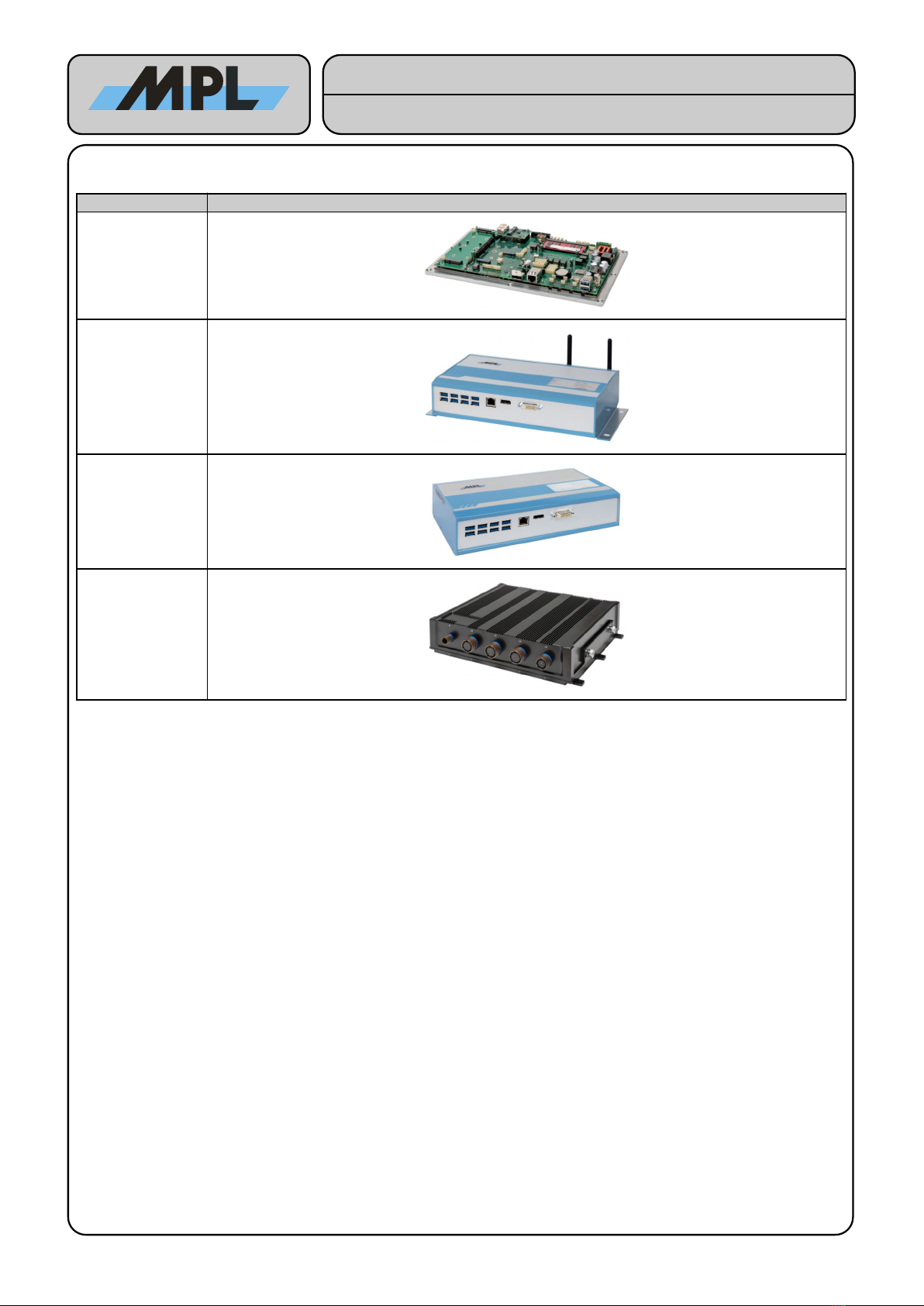
1.7.2 Housing Options
Housing Name Picture
Open rame
Standard
Standard
AN option with
venting openings
on the sides
MIL
2023 b MPL AG 8 MEH-1088-001 Rev. D
High-Tech • Made in Switzerland
PIP4x
User Manual

2 SPECI ICATION
This chapter provides an overview of the PIP4x product and its features
2.1 ELECTRICAL
2.1.1 Processor
•Intel Coffee Lake H and Coffee Lake H Refresh CPU
•Intel Long Life C cle Program (15Y)
•Up to 8 Cores
•Up to 5 GHz
•Up to 16MB Cache
•Up to 45W
•XEON, i9, i7, i5, i3, Pentium and Celeron Processors
•Intel Turbo Boost Technolog 2.0
•cTDP, Configurable TDP
2.1.2 BIOS
•Customizable b MPL
2.1.3 Memory
•2x SO-DIMM 260 DDR4
•Up to 2666 MT/s
•Up to 64GB (2x 32GB)
•ECC (onl supported b XEON and i3 Processors)
2.1.4 Graphics
•Intel HD Graphics 630 (XEON: Intel HD Graphics P630)
•Direct X12, OpenGL 4.6, OpenCL 2.6, Vulkan 1.1.103
•Hardware Video Decode Acceleration MPEG-2 (H.262), MPEG-4 AVC (H.264), JPEG/MJPEG, HEVC
(H.265), VC-1, VP8, VP9
2.1.5 Mass Storage
•2x SATA 6Gb/s (~600MB/s)
•2x mSATA 6Gb/s (~600MB/s)
•m.2 Ke -B SATA 6Gb/s (~600MB/s)
•m.2 Ke -M PCIe x4 (~3500 MB/s) / SATA 6Gb/s (~600MB/s)
2.1.6 Intel AMT (only supported by XEON and i7)
•Remote maintanance and administration over LAN-Interface
•Power ON/OFF
•Serial over LAN-Interface
•Remote Desktop (even in BIOS/UEFI)
•Firmware Update
•Remotel OS Installation
2.1.7 EC (Embedded Controller)
•Voltage and CPU Temperature Supervisor
•Smart Batter Support
•FAN Controller
•Eas in Field Firmware Updates
2023 b MPL AG 9 MEH-1088-001 Rev. D
High-Tech • Made in Switzerland
PIP4x
User Manual

2.1.8 Ethernet
•Intel i219-LM 1Gb/s Ethernet Connection on RJ45
•Optional 2-8 additional Intel i210 1Gb/s Ethernet Controller (9.5KB Jumbo Frame support)
2.1.9 Indicators
•Power LED
•Activit LED (HDD / mPCIe / m.2)
•LAN LED (Speed / Activit )
2.1.10 TPM 2.0
•Infineon SLB9670
•Certification CC EAL4+, FIPS 140-2 level 2
•As mmetric Cr ptograph ECC, ECC BN-256, ECC NIST P-256, ECC256, ECDH, RSA1024, RSA2048
•S mmetric Cr ptograph AES, HMAC, SHA-1, SHA-256
2.1.11 Ignition and Power Button Signal
•Combined Signal, one Pin
•Power Button Signal (active if pulled low)
•Ignition Signal (active if pushed high)
2.1.12 Serial Ports (Optional Modules)
•XR28V384 (V384) Quad Universal As nchronous Receiver and Transmitter (UART)
•Integrated Hardware Watchdog
•16550 UART compatible
•128 B te FIFO
•Up to 115.2 kBaud
•Automatic RS485 direction control (RS-485/RS-422)
•Up to 4 galvanic isolated SERIF-ISO Modules
•SERIF1-ISO (RS-232) TX, RX, RTS, CTS
•SERIF2-ISO (RS-485) RX+/- (RS-485)
2.1.13 Interfaces
•m.2 Ke -A (PCIe x1, USB2.0)
•2x mPCIe (PCIe x1, USB2.0)
•PCIe/104 (PEG x16, PCIe 4x, USB2.0)
•USB2.0
•SPI
•I2C
•PCIe 4x
•eDP
•DP
•SD-Card Header
•HD Audio Header
•12V Header
•SerLED MKII Header
•Smart Batter Header
2023 b MPL AG 10 MEH-1088-001 Rev. D
High-Tech • Made in Switzerland
PIP4x
User Manual
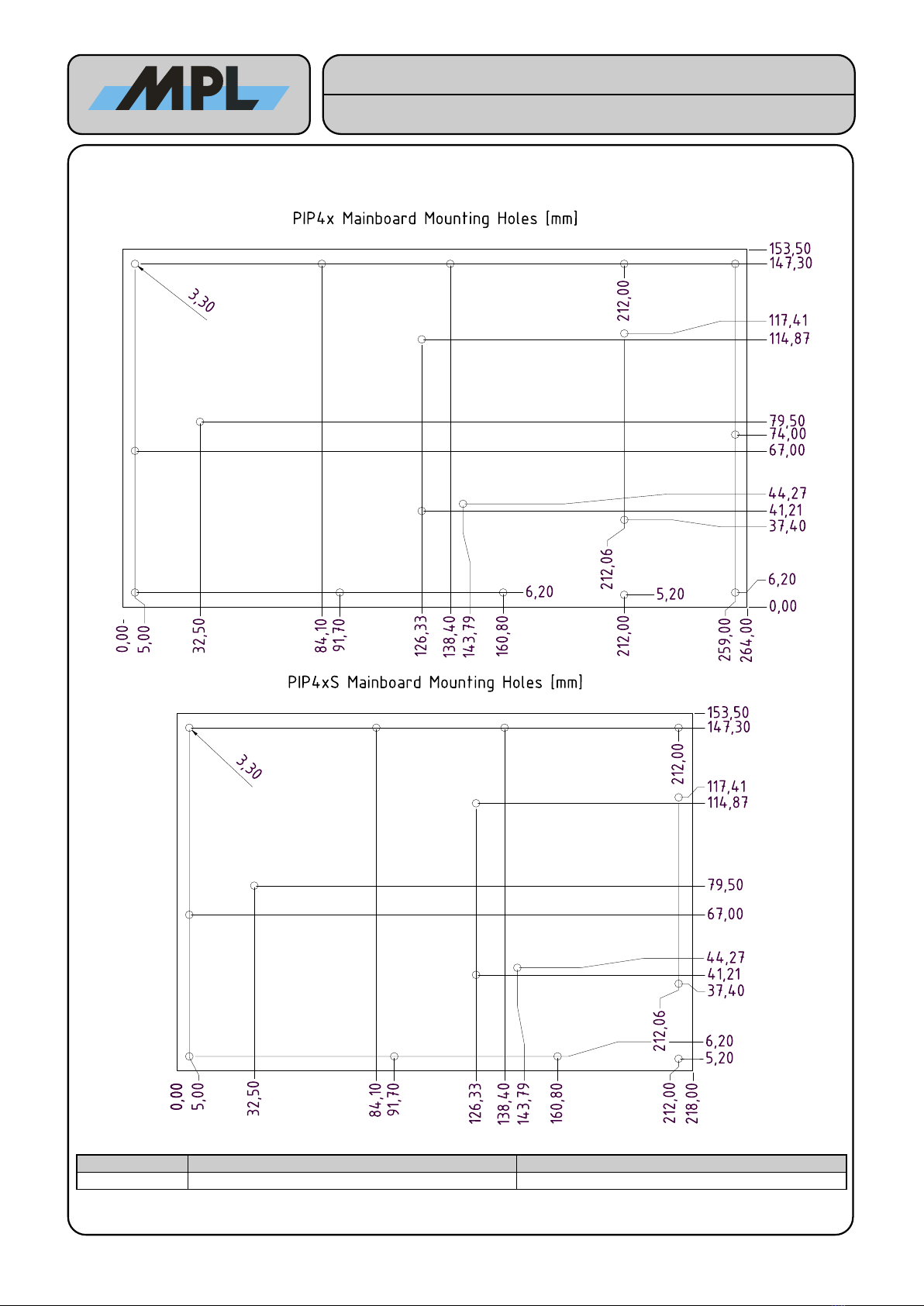
2.2 PHYSICAL
PIP4x Mainboard PIP4xS Mainboard
Weight [g] 360 + 100(Copper Heat Spreader) ~320 + 100(Copper Heat Spreader)
2023 b MPL AG 11 MEH-1088-001 Rev. D
High-Tech • Made in Switzerland
PIP4x
User Manual

2.3 POWER
2.3.1 POWER INPUT
Item Specifications
Input Voltage •10-36 V
Inrush Current The inrush current depends on parameters that are not onl PIP4x specific, like:
•Power suppl internal resistance
•Power suppl voltage rise time and voltage value
•Power cable impedance
Power Up Current •Up to 10A@12V, 5A@24V
Protection Circuits •ESD
•Reverse Polarit
•Over Voltage (60V stead state, IEC 801-4 Level 5)
•Surge, Burst
Recommended
Power Suppl
•24VDC/10A (PIP49R/46R)
•12VDC/10A (PIP41/PIP44R)
When Turbo is enabled, the power transients can be very high. A standard equipped 45W TDP
processor system requires at least 100W of power. Recommended power supply for 45W TDP
processor systems is 24VDC/10A and a 12VDC/10A for 25W TDP systems.
2.3.2 Internal 12V Buck-Boost Converter (Peripheral Power, CPU, Chipset)
The information given below refers to the power which ma be obtained from the connector 12V Peripheral
(J34). The CPU consumption is alread considered. Please note that ever connected
peripheral(PCIe/m.2/USB/PCIe) will decrease the power budget available on 12V Peripheral (J34).
Supply
Voltage [V]
Maximum Allowed Peripheral Power
Consumption @12V [W] for PIP4x 45W CPU
Maximum Allowed Peripheral Power
Consumption @12V [W] for PIP4xL 25W CPU
10 30 50
12 46 66
16 70 90
24 70 90
36 70 90
48 30 30
2.3.3 POWER DISSIPATION
The power consumption changes according to the CPU, memor , graphics and interfaces usage. Please find
some reference values in the table below:
Power State PIP41 PIP44R PIP46R PIP49R
DS5 power state (power save) <0.5 W <0.5 W <0.5 W <0.5 W
S5 power state (standb ) 0.5 W 0.5 W 0.5 W 0.5 W
Ubuntu 18.04 LTS, 8GB DDR4, idle 5 W 5 W 5 W 5 W
Ubuntu 18.04 LTS, 8GB DDR4, stress all CPU 100% avg. 35 W 25 W 45 W 45 W
Ubuntu 18.04 LTS, 8GB DDR4, stress all CPU 100% max. 30s 40 W 30 W 100 W 100 W
2.4 ENVIRONMENTAL CONDITIONS
Item Specifications
Storage Temperature -55 °C to +85 °C
Operating Temperature -20 °C to +60 °C (performance depends on thermal conduction and air flow)
-40 °C to +85 °C (optional screening) (performance depends on thermal conduction)
Adaptive power budget architecture limits processor performance due to maximum internal
processor temperature to protect the device from damage
Shock and Vibration TBD
Relative Humidit 5%-95% non-condensing
2023 b MPL AG 12 MEH-1088-001 Rev. D
High-Tech • Made in Switzerland
PIP4x
User Manual

3 HARDWARE RE ERENCE
3.1 PIP4x
2023 b MPL AG 13 MEH-1088-001 Rev. D
High-Tech • Made in Switzerland
PIP4x
User Manual
J38
J8
J7
J35
J73
J45
J32
J80
J41
J12
J42
J71
J16
J36
J43
J13
J40
J9/J33
J57
J81/82
J84
J44
J65
J28
J31/37/39/92
J76
J23/25/29/30
J17/22/85/86
BAT
J6
J34
J5
J11
J3
J14
J63
S5
J15
BOOT LED

2023 b MPL AG 14 MEH-1088-001 Rev. D
High-Tech • Made in Switzerland
PIP4x
User Manual
Activit LED
J66
J10
LAN LED
Power LED

3.2 PIP4x-xHx (Header Version)
2023 b MPL AG 15 MEH-1088-001 Rev. D
High-Tech • Made in Switzerland
PIP4x
User Manual
J38
J8
J7
J35
J73
J45
J32
J80
J41
J42
J71
J16
J36
J43
J13
J40
J9/J33
J57
J81/82
J84
J44
J65
J28
J31/37/39/92
J76
J23/25/29/30
J19/J21/J24/J26/J86/J87/J90/J91
BAT
J6
J34
J5
J11
J2
J14
J63
S5
J15
BOOT LED
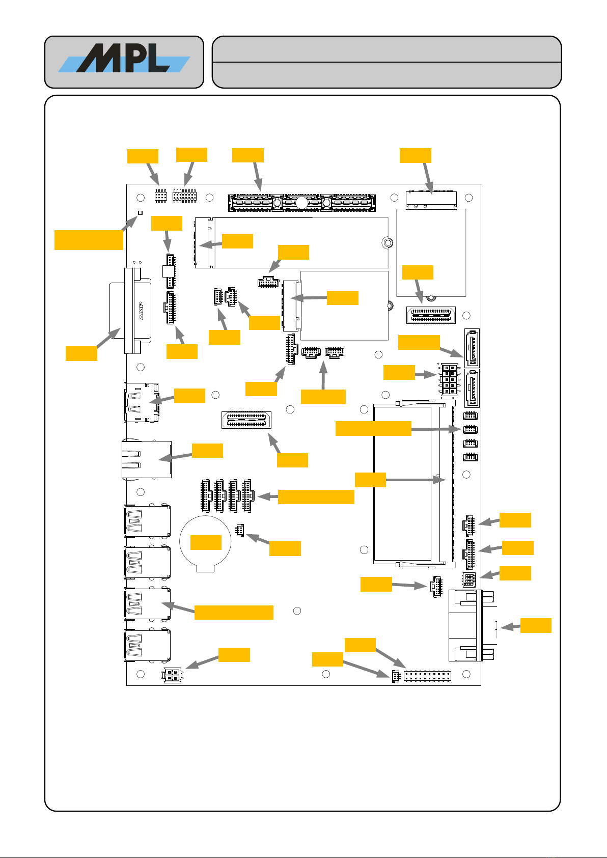
3.3 PIP4xS (Short Version)
2023 b MPL AG 16 MEH-1088-001 Rev. D
High-Tech • Made in Switzerland
PIP4x
User Manual
J73
J45
J32
J80
J41
J42
J71
J16
J36
J43
J13
J40
J9/J33
J57
J81/82
J84
J44
J65
J28
J31/37/39/92
J76
J23/25/29/30
BAT
J6
J34
J5
J11
J14
J63
S5
J15
BOOT LED
J17/22/85/86
J12
J3

2023 b MPL AG 17 MEH-1088-001 Rev. D
High-Tech • Made in Switzerland
PIP4x
User Manual
J66
J10
LAN LED
Power LED
Activit LED

3.4 PIP4xS-xHx (Short Header Version)
2023 b MPL AG 18 MEH-1088-001 Rev. D
High-Tech • Made in Switzerland
PIP4x
User Manual
J73
J45
J32
J80
J41
J42
J71
J16
J36
J43
J13
J40
J9/J33
J57
J81/82
J84
J44
J65
J28
J31/37/39/92
J76
J23/25/29/30
J19/J24/J86/J87/J90/J91
BAT
J6
J34
J5
J11
J2
J14
J63
S5
J15
BOOT LED
J170/J220
3.5 Connector Description
3.5.1 Power Connector (J3)
The power input connector counterpart is: Phoenix Contact AG, PSC 1,5/3-F with a SCT-D-SUB 9-KG case.
Pin
Signal
Description
Pin Assignment
1 VIN Input Voltage
1 3
igure 1: Power Connector (Phoenix Contact AG,
PSC 1,5/3-M-PE)
2
GND
Input Ground
3
PWR/IGN#
Power Button/Ignition# Input
Absolute Maximum Ratings
VIN to GND
+/- 50V
PWR/IGN# to GND
+/- 48V
Recommend Operating Conditions
VIN to GND
10-36V (25W TDP) / 20-36V (45W TDP)
PWR/IGN# to GND
0-36V
Please use AWG16 wire or comparable
PWR/IGN#: This pin is pulled to internal 3V3 (2mA current source). If pulled down a “power button” event is
emitted. When pulled down for more than 4 seconds a “power button overwrite” event is emitted which
immediatel removes the power from CPU. If pulled to a voltage which is higher than 4.8V a “ignition” situation
is detected. In ignition situation the PIP4x will power the CPU while the signal is pulled over 4.3V and initiate
power down sequence if the signal falls below this threshold b emitting power button events to the chipset.
3.5.2 Alternative Power Connector (J1/J2 (horizontal/vertical))
The counterpart for the 4-pin input connector is: Phoenix Contact AG, MC1,5/4STF-3,81.
Pin
Signal
Description
Pin Assignment
1 VIN Input Voltage
igure 2: Power Connector (Connector: Phoenix
Contact AG, MC1,5/4GF-3,81)
2 GND Power Connector Ground
3 GND Power Connector Ground
4 PWR/IGN# Power Button/Ignition# Input
Absolute Maximum Ratings
VIN to GND +/- 50V
PWR/IGN# to GND +/- 48V
Recommend Operating Conditions
VIN to GND 10-36V (25W TDP) / 20-36V (45W TDP)
PWR/IGN# to GND 0-36V
3.5.3 12V Peripheral (J34)
Shrouded 2.54 mm header with latch used to connect ignition-, power- and reset buttons.
Pin
Signal
Signal Description
Pin Assignment
1 12V 12V Power
31
42
2
12V
12V Power
3
GND
Ground
4
GND
Ground
3.5.4 USB 3.1 (J17, J22, J85, J86)
The PIP4x offers up to 8 USB 3.1 ports. Allowed current per port is up to 900mA. These connector ma be
replaced b USB2.0 headers J19, J21, J24, J26, J86, J87, J90, J91.
3.5.5 LAN (J28)
Name Description
Controller/PHY i219-LM
Supported speeds 1000/100/10Mbit
Wake On LAN es
Intel AMT/vPRO Onl available for XEON and i7 t pe processors: PIP49, PIP46
Static LED Orange: 1000Mbit Link, Green: 100Mbit Link
D namic LED Green blinking: Activit
2023 b MPL AG 19 MEH-1088-001 Rev. D
High-Tech • Made in Switzerland
PIP4x
User Manual
3.5.6 Other Interfaces
Number Name Description
J65/66 2x DDR4 SO-DIMM 2667MHz Dual Channel DDR4 RAM (top and bottom side slot) with ECC support
J36 m.2 Ke -A PCIe 2x1 / USB2.0, module size up to 3042
J32 m.2 Ke -B PCIe x1 / SATA / USB3.1 / USB2.0, module size up to 3042, Dual SIM Card Header
J80 m.2 Ke -M NVMe PCIe x4 / SATA, module size up to 2280
J35/38 2x mPCIe/mSATA Full-/Halfsize modules with USB2.0 support, SIM-Card Header on motherboard
J81/82 2x SATA Gen III
J45 PCIe/104 PEG x16, PCIe 4x1, USB2.0
J28 RJ45 1GBit/s Ethernet
J13 Displa port++ DP++ up to 4096x2160@60Hz(when both DDR4 RAM channels are used), Passive
DVI/HDMI Cable Converter Support
J12 DVI-D Digital Video Interface up to 1920x1200@60Hz. Analog video not supported
J17/22
J85/86
J170/220
J850/860
USB 3.1
3.5.7 Serial1-4 LVTTL Connector (J23, J25, J29, J30)
Shrouded 1.00 mm header with positive lock. This interface is intended for the SERIF-ISO isolated RS-232/-485
modules.
Pin
Signal
Signal Description
Pin Assignment
1 DCD Data Carrier Detect (3.3V)
igure 4: Molex, 501331-1207
2 DSR Data Set Read (3.3V)
3 RxD Receive Data (3.3V)
4 RTS Request To Send (3.3V)
5 TxD Transmit Data (3.3V)
6 CTS Clear To Send (3.3V)
7 DTR Data Terminal Read
8 RI Ring Indicator (3.3V)
9 GND GND
0 VCC 5.0V
11 SerConf0 RS232-Protocol: No connection
RS422/485-Protocol: 10kΩ PullDown
12 SerConf1 RS232-Protocol: 10kΩ PullDown
RS422/485-Protocol: No connection
WARNING:
Signal levels must not exceed 3.3V on these connectors!
3.5.8 USB2.0 Header Connectors (J37, J31, J92, J39, *J19, *J21, *J24, *J26, *J86, *J87, *J90, *J91)
Shrouded 1.00 mm header with friction lock. *These connectors are onl optionall assembled as replacement
for J17, J22, J85, J86
Pin
Signal
Signal Description
Pin Assignment
1 VCC USB Power
2
Data-
Negative data signal
3
Data+
Positive data signal
4
GND
Ground
2023 b MPL AG 20 MEH-1088-001 Rev. D
High-Tech • Made in Switzerland
PIP4x
User Manual
This manual suits for next models
1
Table of contents
Other MPL Industrial PC manuals


Popular Industrial PC manuals by other brands


Digital Electronics Corporation
Digital Electronics Corporation PL-3600T Series installation guide

Rockwell Automation
Rockwell Automation Allen-Bradley VersaView 5000 installation instructions

MiTAC
MiTAC MX1-10FEP Series user manual

Avalue Technology
Avalue Technology ERS-AT270-A2 Quick reference guide

FabiaTech
FabiaTech FX5635 user manual

Beckhoff
Beckhoff MIC3100 operating instructions


