MPL PIP8 User manual

PIP8
USERMANUAL
2005 byMPLAG 1MEH-10089-001 Rev. D
PACKEDINDUSTRIALPCWITHINTELPENTIUMIIIPROCESSOR
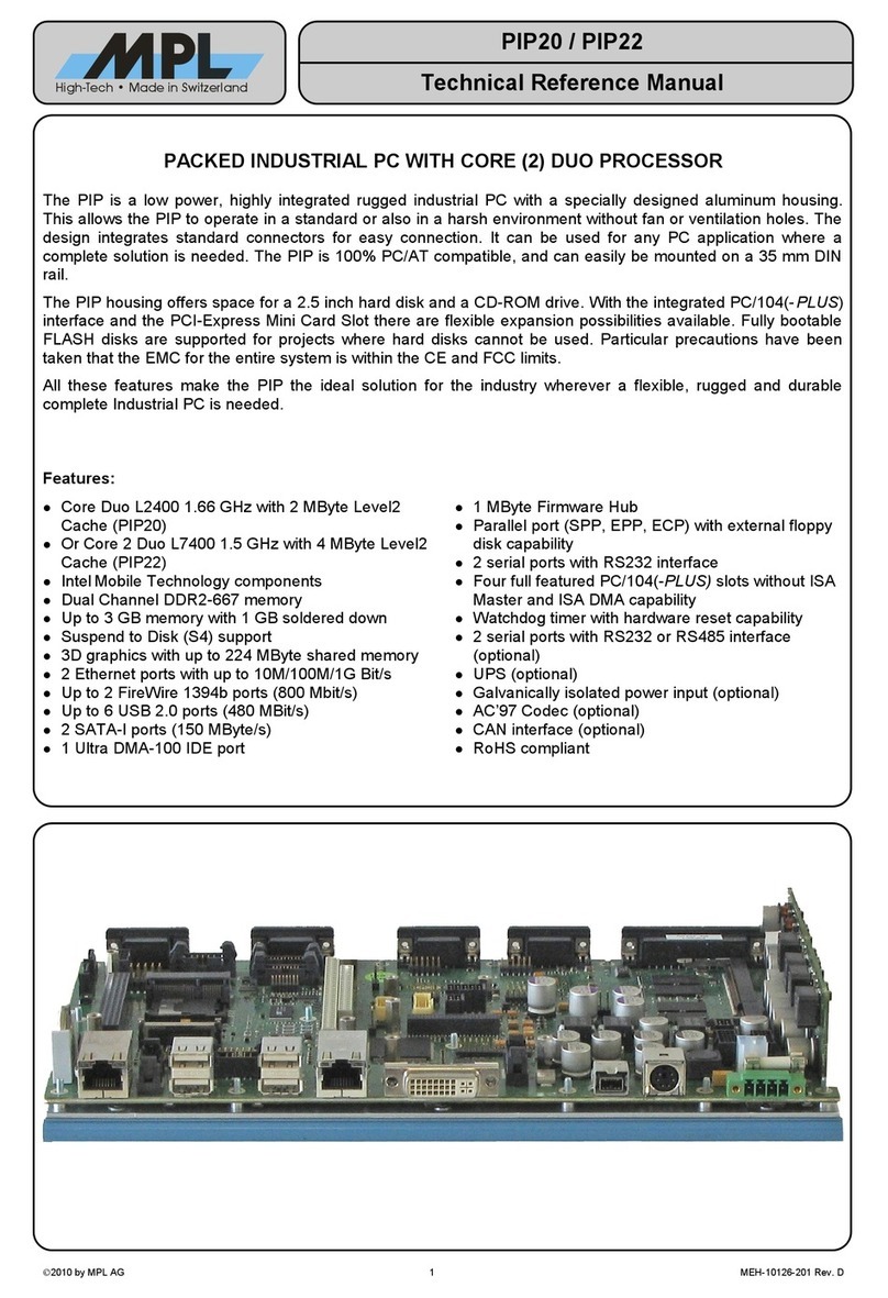
The PIP8isahighlyintegrated robustindustrialPCwithaspeciallydesigned high qualityaluminum
housing.Thisallowsthe systemtooperatewithoutfan orventilation holes.The design integratesstandard
connectorsforeasyconnection.It can be used foranyPCapplication whereacompletesolution isneeded.
The PIP8can be used inastandardorinarugged operating environment, is100% PC/ATcompatibleand
can easilybe mountedon a35mm DINrail.
The PIP8housing offersspacefora2.5inchharddiskand aslim-linefloppydiskdrive.Withthe integrated
PC/104 interfaceflexibleexpansion possibilitiesareavailable.FullybootableFLASHdisksaresupported for
projectswhereharddisksorfloppydiskscannotbe used.Particularprecautionshavebeen taken thatthe
EMCforthe entiresystembe withinthe CEand FCClimits.
Allthesefeaturesmakethe PIP8the ideal solution forthe industry whereveraflexible,rugged,and durable
completeIndustrial PCisneeded.
Features
•LowpowerPentium®III processor
•Processorspeed700 MHz
•Up to256 MbytesSDRAM
•Integrated SXGAgraphicscontroller
•CRT and panelsupport
•Integrated 10/100 Mbit/sEthernet controller
•Integrated SCSI-2Host Controller
•PC/104 and PC/104+interface
•BIOSsourcecode owned byMPL
•M-SystemsDiskOnChip®2000 Support
•Multipurposesocket
•Isolated CANbusinterface
•2USB ports
•Integrated 2.5inchHDD and FDD
•FourRS232 ports
•2isolated half duplexRS485 ports(optional)
•1isolated fullduplexRS422 port(optional)
•Integrated temperaturesensor
•Widesupplyvoltage range

PIP8
USERMANUAL
2005 byMPLAG 2
MEH-10089-001 Rev. D
TABLEOFCONTENTS
1. INTRODUCTION..................................................................................................................................7
1.1. ABOUTTHISMANUAL...................................................................................................................7
1.2. SAFETYPRECAUTIONSAND HANDLING.....................................................................................7
1.3. ELECTROSTATICDISCHARGE(ESD)PROTECTION...................................................................7
1.4. EQUIPMENTSAFETY.....................................................................................................................7
2. GENERALINFORMATIONANDSPECIFICATIONS.............................................................................8
2.1. SPECIFICATIONS...........................................................................................................................8
2.2. REVISIONCHANGES...................................................................................................................13
2.2.1. MECHANICALCHANGES....................................................................................................13
2.2.2. EXTERNALFLOPPYDISKPOWER.....................................................................................13
2.2.3. EXTENSIONREGISTERS....................................................................................................13
2.3. DIMENSIONS................................................................................................................................14
2.3.1. TOPVIEW............................................................................................................................14
2.3.2. BOTTOMVIEW....................................................................................................................15
2.3.3. SIDEVIEW1........................................................................................................................16
2.3.4. SIDEVIEW2........................................................................................................................17
2.3.5. SIDEVIEW3........................................................................................................................18
2.3.6. SIDEVIEW4........................................................................................................................18
3. PREPARATIONFORUSE.................................................................................................................19
3.1. OPENINGTHECASE...................................................................................................................19
3.2. PARTSLOCATION.......................................................................................................................20
3.3. SWITCH SETTINGS......................................................................................................................21
3.3.1. DIPSWITCH 1–DISPLAYSETTINGS.................................................................................21
3.3.2. DIPSWITCH 2–MISCELLANEOUSSETTINGS..................................................................22
3.3.3. DIPSWITCH 3–PERIPHERALSETTINGS..........................................................................22
3.3.4. TERMINATIONSWITCHRS485 PORT 3AND PORT4........................................................23
3.3.5. MPS SWITCH 1....................................................................................................................23
3.3.6. USB PORT 1SWITCH..........................................................................................................23
3.4. EXTERNALCONNECTORS..........................................................................................................24
3.4.1. PARALLELPORT CONNECTOR..........................................................................................24
3.4.2. SERIALPORT 1ANDSERIALPORT2CONNECTOR.........................................................25
3.4.3. SERIALPORT 3ANDSERIALPORT4CONNECTOR.........................................................25
3.4.4. CANCONNECTOR...............................................................................................................26
3.4.5. POWERCONNECTOR.........................................................................................................26
3.4.6. SCSI CONNECTOR..............................................................................................................27
3.4.7. LANCONNECTOR10/100BASETX......................................................................................27
3.4.8. KEYBOARD AND PS/2MOUSE CONNECTOR....................................................................28
3.4.9. USB CONNECTORS............................................................................................................28
3.4.10. VGACRT CONNECTOR......................................................................................................28
3.5. INTERNALCONNECTORS...........................................................................................................29
3.5.1. E-IDECONNECTORS..........................................................................................................29
3.5.1.1. STANDARD E-IDECONNECTOR....................................................................................29
3.5.1.2. CONNECTORFORINTERNALHDD................................................................................29
3.5.2. FDD CONNECTORFORINTERNALFDD............................................................................30
3.5.3. REMOTEMMIMODULECONNECTOR...............................................................................31
3.5.4. ZOOMEDVIDEOPORT CONNECTOR(OPTIONAL)...........................................................32
3.5.5. INTERNALPOWERCONNECTOR.......................................................................................33
3.5.6. SPEAKERCONNECTOR.....................................................................................................33
3.5.7. LEDCONNECTOR...............................................................................................................33
3.5.8. PC/104 INTERFACEPINNUMBERS....................................................................................34

PIP8
USERMANUAL
2005 byMPLAG 3
MEH-10089-001 Rev. D
3.5.9. PC/104+INTERFACE...........................................................................................................35
3.6. CABLEREQUIREMENTS.............................................................................................................35
3.7. MODULESOCKETS.....................................................................................................................36
3.7.1. SO-DIMM MEMORYMODULESOCKET..............................................................................36
3.7.1.1. ELECTRICALAND MECHANICALREQUIREMENTS.......................................................36
3.7.1.2. SUPPORTEDSO-DIMM MODULES.................................................................................36
3.7.1.3. MOUNTINGTHEMEMORYMODULE..............................................................................36
3.7.2. RS485 / RS422 INTERFACEMODULESOCKETS...............................................................37
3.7.3. MULTIPURPOSESOCKET...................................................................................................38
3.7.3.1. MOUNTINGTHEM-SYSTEMSDISKONCHIP®2000 MODULE........................................38
3.7.3.2. DISKONCHIP®2000 MODULESETUP.............................................................................38
3.7.3.3. MEMORYMODULES.......................................................................................................39
3.7.3.3.1. REQUIREDMODULEPROPERTIES..........................................................................39
3.7.3.3.2. MANUFACTURERSOFMEMORYCOMPONENTS....................................................39
3.7.3.3.3. MODULESETUP........................................................................................................40
3.7.3.3.3.1.FLASHTYPEPINOUT..........................................................................................40
3.7.3.3.3.2.EPROMTYPE PINOUT.........................................................................................40
3.7.3.3.3.3.SRAM TYPEPINOUT...........................................................................................40
3.8. REMOTEMMI(REMMI)MODULESOCKET.................................................................................41
3.9. ZV-PORTMODULE.......................................................................................................................42
4. OPERATION......................................................................................................................................43
4.1. BLOCKDIAGRAM.........................................................................................................................43
4.2. PC/ATFUNCTIONALITY...............................................................................................................44
4.3. STATUSINDICATORS..................................................................................................................44
4.3.1. POWERINDICATORLED....................................................................................................44
4.3.2. RESETINDICATORLED......................................................................................................44
4.3.3. HDD ACCESS INDICATORLED...........................................................................................44
4.3.4. SCSI ACCESS INDICATORLED..........................................................................................44
4.3.5. LANACTIVITYINDICATORLED..........................................................................................44
4.3.6. LAN100 INDICATORLED.....................................................................................................44
4.3.7. USER1, USER2 INDICATORLEDS......................................................................................44
4.4. HARDWAREWATCHDOG............................................................................................................45
4.4.1. PROGRAMMINGTHEWATCHDOGTIMER(WDT)..............................................................45
4.4.1.1. INDEXAND DATAPORTS...............................................................................................45
4.4.1.2. ENTERCONFIGURATIONMODE....................................................................................45
4.4.1.3. CONFIGURATIONREGISTERSSETUP..........................................................................45
4.4.1.4. RELOADEVENTSAND RESETSETUP...........................................................................45
4.4.1.5. TIME-OUT UNITSETUP...................................................................................................45
4.4.1.6. TIME-OUT VALUESETUP...............................................................................................45
4.4.1.7. EXIT CONFIGURATIONMODE........................................................................................45
4.4.2. WDTREGISTERS................................................................................................................46
4.4.2.1. WATCHDOGTIMEOUTUNIT REGISTER........................................................................46
4.4.2.2. WATCHDOGTIMEOUTREGISTER.................................................................................46
4.4.2.3. WATCHDOGCONFIGURATIONREGISTER....................................................................46
4.4.2.4. WATCHDOGCONTROLREGISTER................................................................................48
4.5. RS-485 / RS422 INTERFACES.....................................................................................................49
4.5.1. HALF-DUPLEXTRANSMITTERCONTROL..........................................................................49
4.5.2. FULL-DUPLEXMODE..........................................................................................................49
4.5.3. HIGHSPEEDMODE............................................................................................................49
4.6. CANINTERFACE..........................................................................................................................50
4.7. EXTENSIONREGISTERS.............................................................................................................51
4.7.1. UART3RESOURCEREGISTER..........................................................................................51
4.7.2. UART3CONTROLREGISTER.............................................................................................52
4.7.3. UART4RESOURCEREGISTER..........................................................................................53
4.7.4. UART4CONTROLREGISTER.............................................................................................54
4.7.5. CANRESOURCEREGISTER...............................................................................................55
4.7.6. CANCONTROLREGISTER.................................................................................................56

PIP8
USERMANUAL
2005 byMPLAG 4
MEH-10089-001 Rev. D
4.7.7. MULTIPURPOSESOCKETRESOURCEREGISTER...........................................................56
4.7.8. MULTIPURPOSESOCKETPAGEADDRESSREGISTER....................................................57
4.7.9. WATCHDOGCONTROLREGISTER....................................................................................57
4.7.10. USERLEDCONTROLREGISTER.......................................................................................58
4.7.11. STATUSREGISTER1..........................................................................................................58
4.7.12. STATUSREGISTER2..........................................................................................................60
4.7.13. FLOPPYDISK POWERREGISTER......................................................................................61
4.7.14. PIPIDREGISTER................................................................................................................61
4.7.15. PLD PARTIDREGISTER.....................................................................................................61
4.7.16. PLD CODEREVISIONREGISTER.......................................................................................61
4.8. EMCFEATURES...........................................................................................................................62
5. SOFTWARE.......................................................................................................................................63
5.1. BIOS.............................................................................................................................................63
5.2. DEVICEDRIVERS........................................................................................................................63
5.2.1. LINKS TOTHELATESTDRIVERS.......................................................................................63
5.2.2. OTHERLINKS......................................................................................................................63
6. SUPPORT INFORMATION.................................................................................................................64
6.1. MPLAG.........................................................................................................................................64
6.2. PRODUCTIONSERIALAND REVISIONNUMBER.......................................................................64
6.3. RELATEDDOCUMENTS..............................................................................................................64
6.4. DOCUMENTREVISIONHISTORY................................................................................................65

PIP8
USERMANUAL
2005 byMPLAG 5
MEH-10089-001 Rev. D
TABLES
Table1DIPSwitch1-Displaysettings......................................................................................................21
Table2DIPSwitch2-miscellaneoussettings............................................................................................22
Table3DIPSwitch3-peripheralsettings..................................................................................................22
Table4Termination switchRS485.............................................................................................................23
Table5Parallelportconnector...................................................................................................................24
Table6SerialPort 1and SerialPort2Connector.......................................................................................25
Table7SerialPort 3and SerialPort4Connector.......................................................................................25
Table8CANConnector.............................................................................................................................26
Table9PowerConnector...........................................................................................................................26
Table10 SCSI Connector..........................................................................................................................27
Table11 10/100BaseTXconnector............................................................................................................27
Table12 Keyboardand MouseConnector..................................................................................................28
Table13 USBConnector...........................................................................................................................28
Table14 VGAConnector...........................................................................................................................28
Table15 StandardE-IDEConnector..........................................................................................................29
Table16 ConnectorforInternal HDD..........................................................................................................29
Table17 ConnectorforInternal FDD..........................................................................................................30
Table18 RemoteMMI Connector...............................................................................................................31
Table19 Zoomed Video PortConnector.....................................................................................................32
Table20 Internal PowerConnector............................................................................................................33
Table21 SpeakerConnector......................................................................................................................33
Table22 LEDConnector............................................................................................................................33
Table24 PC/104 Connector.......................................................................................................................34
Table26 PC/104+Connector.....................................................................................................................35
Table27 Supported Memory Technologies(440BXChipset)......................................................................36
Table28 Supported SO-DIMMModules.....................................................................................................36
Table29 Watchdog Timeout Unit Register.................................................................................................46
Table30 Watchdog Timeout Register.........................................................................................................46
Table31 Watchdog Configuration Register................................................................................................46
Table32 Watchdog ControlRegister..........................................................................................................48
Table33 UART3ResourceRegister...........................................................................................................51
Table34 UART3ControlRegister..............................................................................................................52
Table35 UART4ResourceRegister...........................................................................................................53
Table36 UART4ControlRegister..............................................................................................................54
Table37 CANResourceRegister...............................................................................................................55
Table38 CANControl Register..................................................................................................................56
Table39 MultipurposeResourceRegister..................................................................................................56
Table40 MultipurposeSocket Page Address Register................................................................................57
Table41 Watchdog ControlRegister..........................................................................................................57
Table42 UserLEDControlRegister...........................................................................................................58
Table43 StatusRegister1.........................................................................................................................58
Table44 StatusRegister2.........................................................................................................................60
Table45 FloppyDiskPowerRegister.........................................................................................................61
Table46 PIPIDRegister............................................................................................................................61
Table47 PLD PartIDRegister...................................................................................................................61
Table48 PLD Code Revision Register.......................................................................................................61
Table49 ESDProtection............................................................................................................................62
Table50 DocumentRevisionHistory..........................................................................................................65

PIP8
USERMANUAL
2005 byMPLAG 6
MEH-10089-001 Rev. D
FIGURES
Figure1Top view.......................................................................................................................................14
Figure2Bottomview..................................................................................................................................15
Figure3Side view1...................................................................................................................................16
Figure4Side view2...................................................................................................................................17
Figure5Side view3...................................................................................................................................18
Figure6Side view4...................................................................................................................................18
Figure7Removing the casescrews...........................................................................................................19
Figure8Lifting up the cover.......................................................................................................................19
Figure9Partslocation...............................................................................................................................20
Figure10 MPSSwitch1.............................................................................................................................23
Figure11 UBS port1Switch......................................................................................................................23
Figure12 ExternalReset and PowerButton Switch....................................................................................26
Figure13 Mounting the MemoryModule....................................................................................................36
Figure14 Mounting the RS485 Modules.....................................................................................................37
Figure15 Mounting the M-SYSTEMDiskOnChip®2000 Module.................................................................38
Figure16 Mounting 32Pinand 28 Pindevices...........................................................................................39
Figure17 FLASHType Pinout....................................................................................................................40
Figure18 EPROMType Pinout..................................................................................................................40
Figure19 SRAM Type Pinout.....................................................................................................................40
Figure20 BlockDiagram............................................................................................................................43
Figure21 Label..........................................................................................................................................64

PIP8
USERMANUAL
2005 byMPLAG 7
MEH-10089-001 Rev. D
1.INTRODUCTION
1.1.ABOUTTHISMANUAL
Thismanual providesallthe information necessary tohandleand configurethe PIP8.
The manualiswritten fortechnicalpersonnelresponsibleforintegrating the PIP8intotheirsystems.
1.2.SAFETYPRECAUTIONSAND HANDLING
Forpersonalsafetyand safeoperation ofthe PIP8,followallsafetyproceduresdescribed hereand inother
sectionsofthe manual.
•Removepowerfromthe systembeforeinstalling (orremoving)the PIP8topreventthe possibilityof
personalinjury (electrical shock) and/ordamage tothe product.
•Handlethe productcarefully;i.e., dropping ormishandling the PIP8can causedamage toassembliesand
components.
•Do not exposethe equipmenttomoisture.
NOTE
Therearenouser-serviceablecomponentsonthePIP8
1.3.ELECTROSTATICDISCHARGE(ESD)PROTECTION
Variouselectricalcomponentswithinthe productaresensitivetostaticand electrostaticdischarge (ESD).
Even asmallstaticdischarge can be sufficienttodestroyordegrade acomponent'soperation!
Withan open housing, do nottouchanyelectroniccomponents. Handleortouchonlythe unit chassis.
1.4.EQUIPMENTSAFETY
Greatcareistaken byMPLthatallitsproductsarethoroughlyand rigorouslytested beforeleaving the
factory toensurethat theyarefullyoperational and conformtospecification.However, no matterhowreliable
aproduct, thereisalwaysthe remotepossibilitythatadefectmayoccur.The occurrenceofadefecton this
devicemay,undercertainconditions,causeadefecttooccurinadjoining and/orconnected equipment.Itis
yourresponsibilitytoprotectsuchequipmentwhen installing thisdevice.MPLacceptsno responsibility
whatsoeverforsuchdefects, howevercaused.

PIP8
USERMANUAL
2005 byMPLAG 8
MEH-10089-001 Rev. D
2.GENERALINFORMATIONAND SPECIFICATIONS
Thischapterprovidesan overviewofthe PIP8and itsfeatures.Itoutlinesthe electricaland physical
specificationsoftheproduct, itspowerrequirements, and alist ofrelated publications.
2.1.SPECIFICATIONS
ELECTRICAL
Processor
•Intel lowpowerembedded Pentium®III CPU„Coppermine“
•SupportsMMXTM technology
•64-bit databus
•16 kbyteinstruction code and 16 kbytewriteback datacacheson-die(L1-cache)
•256 kbyteECC protected cache (L2 -cache)on-die, operatesatfull corespeed
•Pipelined floating point unit(IEEE754)
•Enhanced branchprediction algorithm
•0.18 micron process technology
•Lowpowerconsumption
Chipset
•Intel 440BX
•100 MHzhost busspeed
•SupportsAGPup to2x
BIOSROM
•256 kbyteFLASHEEPROM
•EasyBIOSupdate
Memory
•Socketfora144 pinSO-DIMMmemory module(3.3V)
•SDRAM supported
•Up to256 Mbytes(1module),supportsup to128Mbit chipdensity
•64 bitdatabus
Multipurpose Socket
•SupportsM-SystemsDiskOnChip®2000
•SupportsdifferentSRAM/FLASH/EPROM,28 and 32 pinDILmemory devices
•Memorysizesup to512 kbytes
•Selectablememorywindows
RTC
•Backed withfieldchangeableonboardBattery
•Year2000 compliant
PC/104+interface:
•16 bitPC/104 interface(up to2slots)
•32 bitPC/104+interface(upto2slots)
•Optionalwithadditional extension up to3slots(contactMPLforfurtherinformation)

PIP8
USERMANUAL
2005 byMPLAG 9
MEH-10089-001 Rev. D
VGA
•Chips&Technology69000 GraphicsAccelerator
•Operatesat AGP1x
•64 bitgraphicsengine
•2Mbytevideo memory
•Resolutionsup to1280 x1024 (SXGA)
•Colorsup to16.7M
•Refresh-ratesup to85 Hz
•DPMS and DDC support
•StandardD-sub 15HD VGAconnector
•MPLREMMI (remoteMMI)moduleport, following interfacemodulesareavailable:
•18 Bitparalleldata
•PanelLinkTM
•FPD-Link(FlatPanel Link)
•MPLZVport(Zoomed Video)forvideo input
•FlexiblepanelsupportforSTNand TFTpanels, resolutionsup to1280 x1024
•Optional4Mbytevideo memory using Chips&Technology69030 GraphicsAccelerator
USB
•2USB 1.1portsforserialtransfersat 12 or1.5Mbit/s
•ESDprotected
Serial RS232 ports
•Fourserial RS232 ports
•16C550 compatible(16 byteFIFO)
•Transferratesup to115.2kbaud
•Allmodemsignalsareavailableon 3ports
•Availableon twostandardDB9and one DB25 connector
•Optionally2portscan be equipped withRS485/RS422 interfacemodules
•ESDprotected
RS485/RS422 interface modules (optional)
•Electricallyfullyisolated
•Half-duplex(2-wire)operation
•2modulescan be switched togetherfor1full-duplex(4-wire)port
•Selectabletransferratesup to921.6kbaud
•Availableon DB25 connector
•ESDprotected
Parallelport
•IEEE1284 compliant
•SPP,EPP1.7, EPP1.9,ECPmode support
•ConfigurableasLPT1,LPT2, LPT3
•Floppydiskon parallel port mode
•Availableon DB25 connector
•ESDprotected
IRDAport
•SupportsIrDA1.0/1.1/ ASK-IRmodes
•Half/full-duplexoperation
•Transferratesup to4Mbaud
•Availableon DB25 connector
•ESDprotected

PIP8
USERMANUAL
2005 byMPLAG 10
MEH-10089-001 Rev. D
E-IDEports
•2separateportsforup to4drives
•44 pinheader(internal), 2mm pitch,forinternal 2.5inchnotebookharddisk(primary IDE)
•40 pinheader(internal), 2.54 mm (0.1inch)pitchforserviceand installation purposes(secondary IDE)
•PIO mode 4and busmasterIDE,transfersup to14 Mbytes/s
•UltraDMA/33 mode, synchronousDMA mode transfersup to33Mbytes/s
•Activityindicatoroncasecover
Floppydisk
•Up to2.88 MbytesFDD supported
•26 pinflexcableconnectorused internallyforslimline floppydisk
•Signalscan alsobe routed toparallelportconnector(if externalfloppyisneeded)
CANbus
•Intel AN82527 CANcontroller
•SupportsCANspecification 2.0
•Optoisolated withexternalsupply9Vto28VDC, 100mAmaximum
•Powerinput reversepolarityprotected
•ISO/DIS11898, high speed (1Mbit/s)
•Input +output delay270 nsmaximum
•Availableon aDB-9connector(CiADS102-1)
•DevicedriversforDOS,Windows9x, and LINUXavailable
•ESDprotected
SCSI
•LSI Logic(Symbios)SYM53C810AfastSCSI-2host controller
•Full32 bitPCIbusmaster
•Bootable,integratedSCSIBIOSand configuration utility
•ASPI,SCAM, and fast SCSI-2compatible
•Up to7Mbytes/sasynchronousand 10 Mbytes/ssynchronoustransferrate
•Availableon a50 pinSCSI-2connector
•Hardwarechipdisablefunction
•Devicedriversforallmajoroperating systemsavailable
•Activityindicatoroncasecover
•ESDprotected
Ethernet
•Intel 82559ER-fast 10/100 Mbit/sEthernetcontroller
•Full32 bitPCIbusmaster
•IEEE 802.310BASET and 100BASETXcompatible
•IEEE 802.3u autonegotiation support
•IEEE 802.3x100BASETXflowcontrolsupport
•Hardwarechipdisablefunction
•Activityindicatorsforlinkdetection/network trafficand 100 Mbit/soperation
on casecoverand connector
•Devicedriversforallmajoroperating systemsavailable
•ESDprotected
Keyboard/ mouse
•Availableon 6pinmini DINconnectors(PS/2)
•ESDprotected
Speaker
•Availableon aninternal10 pinheader

PIP8
USERMANUAL
2005 byMPLAG 11
MEH-10089-001 Rev. D
Indicators
•PowerLED(yellow)
•Reset / powerfail LED(red)
•HDD activityLED(green)
•SCSI activityLED(green)
•LANactivityLED(green)
•LAN100 LED(green)
•2user-programmableLED’s(green)
Resetbutton,power button
•Reset button, protected against unintended actuation
•Connection foranexternal remotereset switch
•Connection foranexternal remotepowerbutton switch(ATXfunctionality)
Hardware watchdogtimer
•Programmabletimeout of 1to255 secondsor1to255 minutes
Temperature sensor
•Monitorsthe CPUtemperature

PIP8
USERMANUAL
2005 byMPLAG 12
MEH-10089-001 Rev. D
PHYSICAL/POWER
Housing
•Aluminum
•No ventilation holes
•Easilymountableon 35mm DINrail
Form factor
Length:270 mm (10.63 inch)
Width:162 mm (6.38 inch)
Height:62 mm (2.44 inch)standardversion
78 mm (3.07 inch)high version
Weight
Typicallyapproximately2.2kg(4.85 lb)
(Standardhousing version,equipped withinternal 2.5inchHDD and FDD)
Power supply
High-efficiency 4channelswitching regulatormodule
ATXbehavior(Soft off)
ESDprotected
Fuse
5x20 mm, 3.15 AT
Battery
LithiumCoinCell CR2032 (20.0x3.2mm)
3V/235 mAh
Fieldchangeable
InputPower Range
+8Vto+28 VDC
Power consumption
typical17W
ENVIRONMENT
Temperature range
0°Cto+60°C(+32°F to+140°F)withoutinternalHDDorFDD.
Extended temperaturerange available
Relative humidity
10% to90% noncondensing

PIP8
USERMANUAL
2005 byMPLAG 13
MEH-10089-001 Rev. D
2.2.REVISIONCHANGES
Forthe PIP8revision Corabove,someadditionalfeatureshasbeen implemented.Thereforitis
recommended tousethismanualforthe PIP8revision Corlaterrevisions.
Thissection showsthe differencesbetween thisand earlierrevisions.
2.2.1.MECHANICAL CHANGES
The speakerconnectorhasbeen turned around 180°.Refertothe mechanicaldrawingsatsection 3.2for
information.
2.2.2.EXTERNAL FLOPPYDISKPOWER
Anewfeatureisthe availablepowerpinatthe parallelport(pin25)tousewithan external parallel port
floppy.The powersetting can be selectedinthe BIOS.
2.2.3.EXTENSIONREGISTERS
The meaningsofthe following extension registershavechanged:
800h -UT3RES (referto4.7.1),802h –UT4RES (referto4.7.3),804h –CANRES(referto4.7.5),80Ch -
FDPR(referto4.7.13).
Softwarethat usesthe extension registersmust be checked and maybe modified.

PIP8
USERMANUAL
2005 byMPLAG 14
MEH-10089-001 Rev. D
2.3.DIMENSIONS
2.3.1.TOPVIEW
SIDE VIEW 3
SIDE VIEW 4
SIDE VIEW 1
SIDE VIEW 2
162,1
270,0
32.5
40.1
47.7
55.4
63.0
70.6
78.2
85.8
106.2
48.3
P R - + KEYB MOUSE SCSI VGA USB LAN
High-Tech Made in Switzerland
Power
Reset
HDD
SCSI
LAN
LAN100
User1
User2
Reset
PARALLEL SERIAL 1 SERIAL 2 SERIAL 3 + 4 CAN
Figure1Top view

PIP8
USERMANUAL
2005 byMPLAG 15
MEH-10089-001 Rev. D
2.3.2.BOTTOMVIEW
SIDE VIEW 3
SIDE VIEW 2
SIDE VIEW 1
SIDE VIEW 4
85,0
185,0
59,5
109,5
270,0
162,1
81,1
105,0
165,0
Figure2Bottomview
Note: All dimensionsaresubjecttochange.

PIP8
USERMANUAL
2005 byMPLAG 16
MEH-10089-001 Rev. D
2.3.3.SIDEVIEW1
62,0 SIDEVIEW4
BOTTOM VIEW
TOP VIEW
270.0
DSUB-25DSUB-9 DSUB-9 DSUB-9DSUB-25
85.0
185.0
24,3
29,9
33.4
40,9
48.4
82,3 x 15
82,3 x 15
8,5
21,2 73,3
103,4
106.9
165.4
168,9
221,0
251,1
17,7 64,7
81,8
106,8
122,5
147,5
165,3
212,3
229,6
254,6
SIDEVIEW3 (49,4)
(56,9)
(64,4)
(82,5), [120,0]
(45,9)
Figure3Sideview1
Note: Usenumbersinparenthesesforthehigh version (82.5mm)[120mm].Alldimensionsaresubject tochange.

PIP8
USERMANUAL
2005 byMPLAG 17
MEH-10089-001 Rev. D
2.3.4.SIDEVIEW2
SIDEVIEW4
TOP VIEW
BOTTOM VIEW
62.0
270.0
85.0
185.0
270.0
8,5
23,2
52,1
76,5
101,5
120,8
167,2
190,6
208,2
232,1
21,0
24,5
23,4
24,5
22,1
30,7
24,8
252,1
SIDEVIEW3
(82,5),[120,0]
Figure4Sideview2
Note: Usenumbersinparenthesesforthehigh version (82.5mm)[120mm].Alldimensionsaresubject tochange.

PIP8
USERMANUAL
2005 byMPLAG 18
MEH-10089-001 Rev. D
2.3.5.SIDEVIEW3
SIDE VIEW 2
BOTTOMVIEW
SIDE VIEW 1
109.5
59.5
162,1
62,0
46.4
33.4
43,0
67,7
110,9
144,9
17,2
94,4
4,6
57,4
8,5
(82,5), [120,0]
(77,9), [115,4]
TOPVIEW
Figure5Sideview3
2.3.6.SIDEVIEW4
TOPVIEW
SIDE VIEW 1
BOTTOMVIEW
SIDE VIEW 2
102.5
52.5
162,1
62,0
94,4
144,9
17,2
67,7
4,6
57,4
8,5
107,5
35,4
(82,5), [120,0]
(77,9), [115,4]
Figure6Sideview4
Note: Usenumbersinparenthesesforthehigh version (82.5mm)[120mm]. Alldimensionsaresubject tochange.

PIP8
USERMANUAL
2005 byMPLAG 19
MEH-10089-001 Rev. D
3.PREPARATIONFORUSE
3.1.OPENING THECASE
Removethe screwsfromthe casetop.
Figure7Removingthecasescrews
Liftup the coverslowly.Pleasebe carefulwiththe cables.
Figure8Liftingupthecover

PIP8
USERMANUAL
2005 byMPLAG 20
MEH-10089-001 Rev. D
3.2.PARTSLOCATION
1O
N
2
3
4
5
6
7
8
1O
N
2
3
4
5
6
7
8
1O
N
2
3
4
40
1
44
1
1
10
1
10
50
1
40
1
1
50
1 32
1 28 1 28
1
10
1
144
AB 1
DC
0
32
19
ABCD
1
30
1 26
Parallel Port
Connector Serial Port 1
Connector Serial Port 2
Connector Serial Port 3+4
Connector CAN Bus
Connector
10BaseT/100BaseTX
Connector
USB Port 1+2
Connector
VGA
Connector
SCSI
Connector
Mouse
Connector
Keyboard
Connector
Power
Connector Secondary IDE
Connector
Primary IDE
Connector
(internal HDD)
Serial Port 3
RS485 Module
Socket
Serial Port 4
RS485 Module
Socket
PC/104
Connector
PC/104
Connector
internal FDD
Connector
Termination
Switch RS485
Port 3+4
Multi Purpose
Socket
DIP Switch 1
USB Port 1
Switch
REMMI-T
Module
Connector
ZV Port
Module
Connector
MPS Switch 1
USB Port
Switch 1
MPL Use
Only
144 Pin
SO-DIMM
Memory Socket
LED Panel
Connector
Batterie
DIP Switch 2
Speaker
Connector
MPL Use Only
1O
N
2
3
4
5
6
7
8
DIP Switch 3
14
58
Figure9Partslocation
Table of contents
Other MPL Industrial PC manuals
Popular Industrial PC manuals by other brands
Allen-Bradley
Allen-Bradley 6181X-NPXPDC installation instructions
IEI Technology
IEI Technology ECW-281B-945GSE user manual
Chipsee
Chipsee PPC-A55-236 manual
Advantech
Advantech UNO-3483G Series user manual

Moxa Technologies
Moxa Technologies TC-6110 Series Quick installation guide

Janz Tec
Janz Tec emPC-CX+/C-1047UE Hardware manual
