Chapter2 SystemComponents
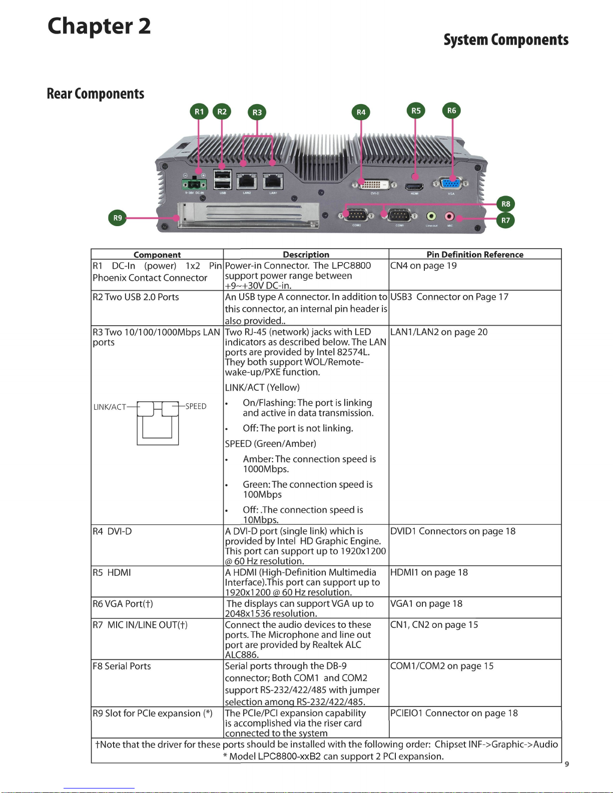
RearComponents
Component Description PinDefinitionReference
R1DC-ln(power)1x2Pin
PhoenixContactConnector Power-inConnector.TheLPC8800
supportpowerrangebetween
+9~+30VDC-in.
CN4onpage19
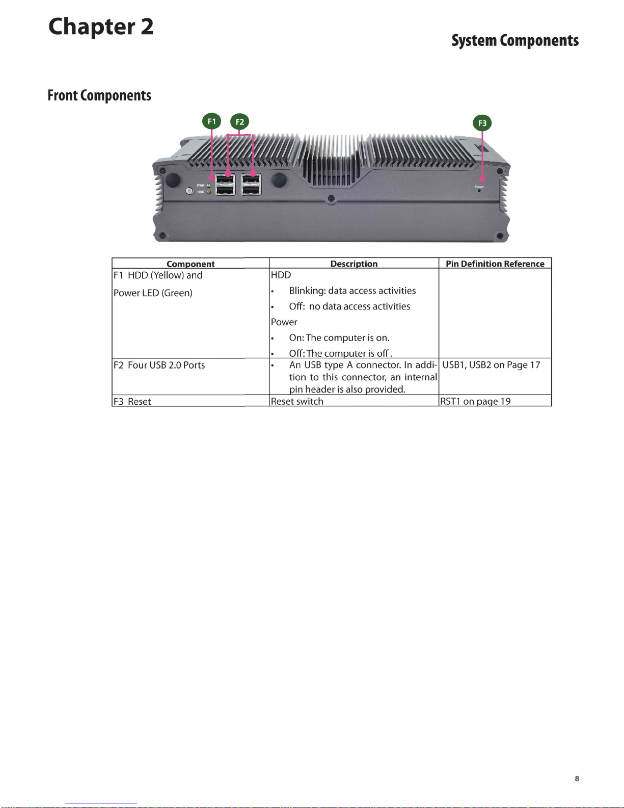
R2
TwoUSB2.0Ports AnUSBtypeA connector.Inadditionto
thisconnector,aninternalpinheaderis
alsoprovided..
USB3ConnectoronPage17
R3
Two10/100/1000MbpsLAN
ports TwoRJ-45(network)jackswithLED
indicatorsasdescribedbelow.TheLAN
portsareprovidedbyIntel82574L.
TheybothsupportWOL/Remote-
wake-up/PXEfunction.
LINK/ACT(Yellow)
On/Flashing:Theportislinking
andactiveindatatransmission.
Off:Theportisnotlinking.
SPEED(Green/Amber)
Amber:Theconnectionspeedis
1000Mbps.
Green:Theconnectionspeedis
100Mbps
Off:Theconnectionspeedis
10Mbps.
LAN1/LAN2onpage20
LINK/ACT— -SPEED
TwoRJ-45(network)jackswithLED
indicatorsasdescribedbelow.TheLAN
portsareprovidedbyIntel82574L.
TheybothsupportWOL/Remote-
wake-up/PXEfunction.
LINK/ACT(Yellow)
On/Flashing:Theportislinking
andactiveindatatransmission.
Off:Theportisnotlinking.
SPEED(Green/Amber)
Amber:Theconnectionspeedis
1000Mbps.
Green:Theconnectionspeedis
100Mbps
Off:Theconnectionspeedis
10Mbps.
LAN1/LAN2onpage20TwoRJ-45(network)jackswithLED
indicatorsasdescribedbelow.TheLAN
portsareprovidedbyIntel82574L.
TheybothsupportWOL/Remote-
wake-up/PXEfunction.
LINK/ACT(Yellow)
On/Flashing:Theportislinking
andactiveindatatransmission.
Off:Theportisnotlinking.
SPEED(Green/Amber)
Amber:Theconnectionspeedis
1000Mbps.
Green:Theconnectionspeedis
100Mbps
Off:Theconnectionspeedis
10Mbps.
LAN1/LAN2onpage20
R4DVI-D ADVI-Dport(singlelink)whichis
providedbyIntelHDGraphicEngine.
Thisportcansupportupto1920x1200
&60Hzresolution.
DVID1Connectorsonpage18
R5HDMI AHDMI(High-DefinitionMultimedia
lnterface).Thisportcansupportupto
1920x1200(a60Hzresolution.
HDMI1onpage18
R6VGAPort(t) ThedisplayscansupportVGAupto
2048x1536resolution. VGA1onpage18
R7MICIN/LINEOUT(t) Connecttheaudiodevicestothese
ports.
TheMicrophoneandlineout
portareprovidedbyRealtekALC
ALC886.
CN1,CN2onpage15
F8SerialPorts SerialportsthroughtheDB-9
connector;Both
COM1
andCOM2
supportRS-232/422/485withjumper
selectionamonqRS-232/422/485.
COM1/COM2onpage15
R9SlotforPCIeexpansion(*) ThePCIe/PCIexpansioncapability
isaccomplishedviatherisercard
connectedtothesystem
PCIEI01Connectoronpage18
tNotethatthedriverfortheseportsshouldbeinstalledwiththefollowingorder:ChipsetINF->Graphic->Audio
*ModelLPC8800-xxB2cansupport2 PCIexpansion.