MPL PIP20 Product manual
PACKED INDUSTRIAL PC WITH CORE (2) DUO PROCESSOR
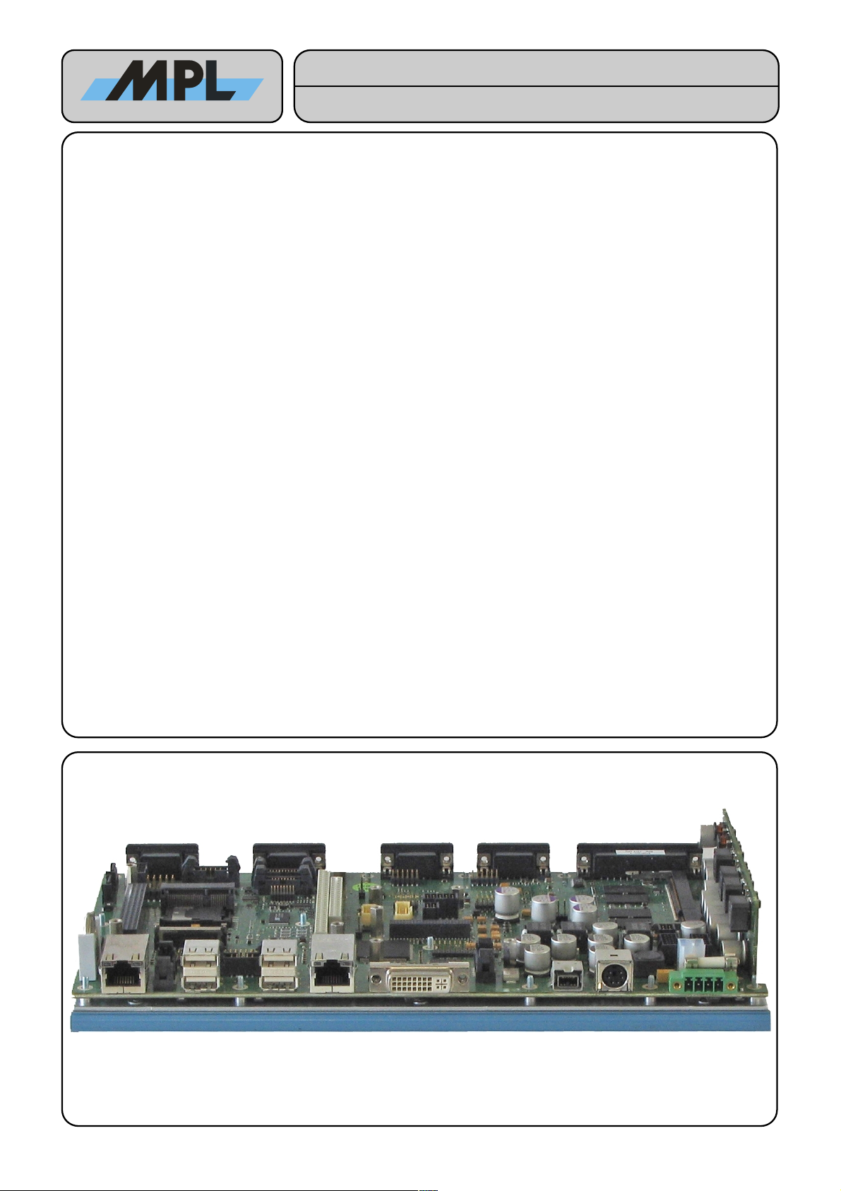
The PIP is a low power, highly integrated rugged industrial PC with a specially designed aluminum housing.
This allows the PIP to operate in a standard or also in a harsh environment without fan or ventilation holes. The
design integrates standard connectors for easy connection. It can be used for any PC application where a
complete solution is needed. The PIP is 100% PC AT compatible, and can easily be mounted on a 35 mm DIN
rail.
The PIP housing offers space for a 2.5 inch hard disk and a CD-ROM drive. With the integrated PC 104(- PLUS)
interface and the PCI-Express Mini Card Slot there are flexible expansion possibilities available. Fully bootable
FLASH disks are supported for projects where hard disks cannot be used. Particular precautions have been
taken that the EMC for the entire system is within the CE and FCC limits.
All these features make the PIP the ideal solution for the industry wherever a flexible, rugged and durable
complete Industrial PC is needed.
Features:
●Core Duo L2400 1.66 GHz with 2 MByte Level2
Cache (PIP20)
●Or Core 2 Duo L7400 1.5 GHz with 4 MByte Level2
Cache (PIP22)
●Intel Mobile Technology components
●Dual Channel DDR2-667 memory
●Up to 3 GB memory with 1 GB soldered down
●Suspend to Disk (S4) support
●3D graphics with up to 224 MByte shared memory
●2 Ethernet ports with up to 10M 100M 1G Bit s
●Up to 2 FireWire 1394b ports (800 Mbit s)
●Up to 6 USB 2.0 ports (480 MBit s)
●2 SATA-I ports (150 MByte s)
●1 Ultra DMA-100 IDE port
●1 MByte Firmware Hub
●Parallel port (SPP, EPP, ECP) with external floppy
disk capability
●2 serial ports with RS232 interface
●Four full featured PC 104(-PLUS) slots without ISA
Master and ISA DMA capability
●Watchdog timer with hardware reset capability
●2 serial ports with RS232 or RS485 interface
(optional)
●UPS (optional)
●Galvanically isolated power input (optional)
●AC’97 Codec (optional)
●CAN interface (optional)
●RoHS compliant
2010 by MPL AG 1 MEH-10126-201 Rev. D
High-Tech • Made in Switzerland
PIP20 / PIP22
Tec nical Reference Manual

TABLE OF CONTENTS
1 INTRODUCTION.............................................................................................................7
1.1 ABOUT THIS MANUAL.........................................................................................................7
1.2 SAFETY PRECAUTIONS AND HANDLING..........................................................................7
1.3 ELECTROSTATIC DISCHARGE (ESD) PROTECTION........................................................7
1.4 EQUIPMENT SAFETY...........................................................................................................7
1.5 MANUAL REVISIONS............................................................................................................8
1.5.1 RELATED PRODUCTS.................................................................................................. 8
1.5.2 REVISION HISTORY.....................................................................................................8
1.6 RELATED DOCUMENTATION..............................................................................................9
1.7 STANDARDS COMPLIANCE.............................................................................................. 10
1.7.1 EMC............................................................................................................................. 10
1.7.2 Environmental............................................................................................................... 10
1.7.3 Safety........................................................................................................................... 10
1.7.4 Type Approval.............................................................................................................. 10
1.8 ORDERING INFORMATION................................................................................................ 11
2 SPECIFICATION...........................................................................................................12
2.1 ELECTRICAL....................................................................................................................... 12
2.1.1 PROCESSOR............................................................................................................... 12
2.1.2 CHIPSET...................................................................................................................... 12
2.1.3 BIOS ROM.................................................................................................................... 12
2.1.4 MEMORY..................................................................................................................... 12
2.1.5 RTC.............................................................................................................................. 12
2.1.6 PC 104-PLUS INTERFACE..........................................................................................12
2.1.7 GRAPHICS................................................................................................................... 12
2.1.8 USB.............................................................................................................................. 12
2.1.9 SERIAL PORTS........................................................................................................... 12
2.1.10 RS485 RS422 INTERFACE MODULES (OPTIONAL)...............................................13
2.1.11 PARALLEL PORT......................................................................................................13
2.1.12 IDE PORTS................................................................................................................ 13
2.1.13 SATA-I PORTS........................................................................................................... 13
2.1.14 FLOPPY DISK............................................................................................................ 13
2.1.15 FIREWIRE 1394B....................................................................................................... 13
2.1.16 ETHERNET................................................................................................................ 13
2.1.17 KEYBOARD MOUSE................................................................................................13
2.1.18 AC’97 AUDIO CONTROLLER....................................................................................13
2.1.19 INDICATORS............................................................................................................. 13
2.1.20 RESET BUTTON, POWER BUTTON.........................................................................14
2.1.21 HARDWARE WATCHDOG TIMER............................................................................14
2.1.22 TEMPERATURE SENSORS.....................................................................................14
2.1.23 VOLTAGE SENSORS................................................................................................14
2.1.24 SPECIALTIES............................................................................................................ 14
2.2 PHYSICAL........................................................................................................................... 15
2.2.1 HOUSING..................................................................................................................... 15
2.2.2 FORM FACTOR........................................................................................................... 15
2.2.3 WEIGHT....................................................................................................................... 15
2.3 POWER................................................................................................................................ 15
2.3.1 POWER SUPPLY.........................................................................................................15
2.3.2 FUSE............................................................................................................................ 15
2.3.3 RTC BATTERY............................................................................................................. 15
2010 by MPL AG 2 MEH-10126-201 Rev. D
High-Tech • Made in Switzerland
PIP20 / PIP22
Tec nical Reference Manual

2.3.4 INPUT POWER............................................................................................................ 15
2.4 ENVIRONMENT................................................................................................................... 15
2.4.1 TEMPERATURE RANGE.............................................................................................15
2.4.2 RELATIVE HUMIDITY..................................................................................................15
3 HARDWARE REFERENCE..........................................................................................16
3.1 HOUSING DIMENSIONS.....................................................................................................16
3.1.1 TOP VIEW.................................................................................................................... 16
3.1.2 BOTTOM VIEW............................................................................................................ 17
3.1.3 SIDE VIEW 1................................................................................................................ 18
3.1.4 SIDE VIEW 2................................................................................................................ 19
3.1.5 SIDE VIEW 3................................................................................................................ 20
3.1.6 SIDE VIEW 4................................................................................................................ 20
3.2 OPENING THE CASE.......................................................................................................... 21
3.3 DIMENSIONS AND PLACEMENT.......................................................................................22
3.3.1 DIMENSIONS OF THE PCB........................................................................................22
3.3.2 PARTS LOCATION......................................................................................................23
3.4 SWITCH SETTINGS............................................................................................................. 24
3.4.1 DIP SWITCH 1 (S1) – PERIPHERAL SETTINGS........................................................24
3.4.2 DIP SWITCH 2 (S2) – ON BOARD LVDS PORT (LCD PANEL) SETTINGS...............25
3.4.3 DIP SWITCH 3 (S3) – PC 104-PLUS IO-VOLTAGE SETTINGS..................................25
3.4.4 DIP SWITCH 4 (S4)......................................................................................................25
3.5 CONNECTORS.................................................................................................................... 26
3.5.1 EXTERNAL CONNECTORS........................................................................................26
3.5.1.1 Parallel Port Connector (J3)..................................................................................................26
3.5.1.2 Serial-1 (J49) And Serial-3 (J37) Connector.........................................................................27
3.5.1.3 Serial-2 (J22) And Serial-4 (J12) Connector.........................................................................27
3.5.1.4 External Power Connector (J2).............................................................................................28
3.5.1.5 PS 2 Keyboard And Mouse Connector (J8)..........................................................................30
3.5.1.6 FireWire 1394b Connector (J11)...........................................................................................30
3.5.1.7 Dual USB Connectors (J40, J46)..........................................................................................30
3.5.1.8 DVI-I Connector (J20)...........................................................................................................31
3.5.1.9 10M 100M 1G Bit s Ethernet Connectors (LAN1: J52, LAN2: J33)......................................31
3.5.2 INTERNAL CONNECTORS.........................................................................................32
3.5.2.1 IDE Connector (J41).............................................................................................................32
3.5.2.2 SATA Signal Connectors (J56, J57).....................................................................................32
3.5.2.3 SATA Power Connector (J54)...............................................................................................32
3.5.2.4 LED Panel Connector 1 (J38)...............................................................................................33
3.5.2.5 LED Panel Connector 2 (J39)...............................................................................................33
3.5.2.6 sDVO Expansion Module Connector (J19)...........................................................................34
3.5.2.7 LVDS Connector (J27)..........................................................................................................35
3.5.2.8 Touch Panel Connector (J21)...............................................................................................35
3.5.2.9 Backlight Inverter Connector (J28)........................................................................................36
3.5.2.10 Panel Dimming Connector (J24).........................................................................................36
3.5.2.11 Internal Power Connector 1 (J4).........................................................................................36
3.5.2.12 Internal Power Connector 2 (J6).........................................................................................37
3.5.2.13 Power Input Extension Connector (J5)...............................................................................37
3.5.2.14 AC’97 Connector (J47)........................................................................................................37
3.5.2.15 USB2.0 Header Connector (J43)........................................................................................37
3.5.2.16 Firewire Header Connector (J14)........................................................................................38
3.5.2.17 Reset & Power Button Connector (J7)................................................................................38
3.5.2.18 CAN Expansion Connector (J35)........................................................................................38
3.5.2.19 PC 104 Interface Connector (J29 J36)................................................................................39
3.5.2.20 PC 104-PLUS Interface Connector (J53)............................................................................40
3.5.2.21 SMB Connector (J48)..........................................................................................................40
3.5.2.22 IPT700 Connector (J14)......................................................................................................40
3.5.2.23 JTAG Port Connector (J50).................................................................................................40
3.5.2.24 LPC Bus Expansion Connector (J42).................................................................................40
3.6 MODULE SOCKETS............................................................................................................ 41
2010 by MPL AG 3 MEH-10126-201 Rev. D
High-Tech • Made in Switzerland
PIP20 / PIP22
Tec nical Reference Manual

3.6.1 MEMORY MODULE.....................................................................................................41
3.6.1.1 Electrical And Mechanical Requirements..............................................................................41
3.6.1.2 Mounting The Memory Module.............................................................................................41
3.6.2 RS232 AND RS485 RS422 INTERFACE MODULES................................................41
3.6.3 PC 104(-PLUS) MODULES..........................................................................................41
3.6.4 PCI-EXPRESS MINI CARD MODULES.......................................................................41
3.7 SYSTEM-VOLTAGES SUPPLIED BY THE PIP..................................................................42
3.7.1 -12 V, -5 V AND 12 V...................................................................................................42
3.7.2 3.3 V, 5 V and 5 V Standby..........................................................................................42
4 THEORY OF OPERATION............................................................................................43
4.1 BLOCK DIAGRAM............................................................................................................... 43
4.2 PC/AT FUNCTIONALITY.....................................................................................................44
4.3 STATUS INDICATORS........................................................................................................ 44
4.3.1 POWER INDICATOR LED...........................................................................................44
4.3.2 RESET INDICATOR LED.............................................................................................44
4.3.3 HDD INDICATOR LED.................................................................................................44
4.3.4 IEEE1394b INDICATOR LED.......................................................................................44
4.3.5 LAN 1 Activity INDICATOR LED...................................................................................44
4.3.6 LAN 1 Speed INDICATOR LED....................................................................................44
4.3.7 USER1, USER2 INDICATOR LEDS.............................................................................44
4.3.8 Wireless WAN INDICATOR LED..................................................................................44
4.3.9 Wireless LAN INDICATOR LED...................................................................................44
4.3.10 Wireless PAN INDICATOR LED.................................................................................44
4.3.11 LAN 2 Activity INDICATOR LED.................................................................................45
4.3.12 LAN 2 Speed INDICATOR LED..................................................................................45
4.4 BATTERY CIRCUIT............................................................................................................. 45
4.5 HARDWARE WATCHDOG.................................................................................................. 45
4.6 RS485 / RS422 INTERFACES.............................................................................................45
4.7 TEMPERATURE SENSORS................................................................................................ 45
4.8 VOLTAGE SENSORS.......................................................................................................... 46
5 SOFTWARE..................................................................................................................47
5.1 PIP EXTENSION REGISTER SET.......................................................................................47
5.1.1 OVERVIEW.................................................................................................................. 47
5.1.2 CAN RESOURCE REGISTER.....................................................................................48
5.1.3 CAN CONTROL REGISTER........................................................................................49
5.1.4 USER LED CONTROL REGISTER..............................................................................50
5.1.5 PIP STATUS REGISTER 1..........................................................................................50
5.1.6 PIP STATUS REGISTER 2..........................................................................................51
5.1.7 PARALLEL PORT FLOPPY REGISTER......................................................................51
5.1.8 PIP FAMILY ID REGISTER..........................................................................................51
5.1.9 PIP20 VARIANT REGISTER........................................................................................52
5.1.10 PLD CODE REVISION REGISTER............................................................................52
5.2 BIOS..................................................................................................................................... 53
5.3 DEVICE DRIVERS............................................................................................................... 53
5.4 TOOLS................................................................................................................................. 53
6 COPYRIGHT................................................................................................................. 56
7 DISCLAIMER................................................................................................................56
8 TRADEMARKS.............................................................................................................56
2010 by MPL AG 4 MEH-10126-201 Rev. D
High-Tech • Made in Switzerland
PIP20 / PIP22
Tec nical Reference Manual

9 SUPPORT.....................................................................................................................56
9.1 FAQs.................................................................................................................................... 56
9.2 SERIAL NUMBER AND REVISION.....................................................................................56
9.3 CONTACT MPL AG............................................................................................................. 56
2010 by MPL AG 5 MEH-10126-201 Rev. D
High-Tech • Made in Switzerland
PIP20 / PIP22
Tec nical Reference Manual

TABLE OF FIGURES
Figure 1: PIP2x Housing Top View...................................................................................................................... 16
Figure 2: PIP2x Housing Bottom View................................................................................................................. 17
Figure 3: PIP2x Housing Side View 1.................................................................................................................. 18
Figure 4: PIP2x Housing Side View 2.................................................................................................................. 19
Figure 5: PIP2x Housing Side View 3.................................................................................................................. 20
Figure 6: PIP2x Housing Side View 4.................................................................................................................. 20
Figure 7: Removing The 6 Screws....................................................................................................................... 21
Figure 8: Lift Up The Cover.................................................................................................................................. 21
Figure 9: Locations Of The Standoff And Mounting Holes...................................................................................22
Figure 10: Parts Location..................................................................................................................................... 23
Figure 11: DIP Switch 1....................................................................................................................................... 24
Figure 12: DIP Switch 2....................................................................................................................................... 25
Figure 13: DIP Switch 3....................................................................................................................................... 25
Figure 14: DIP Switch 4....................................................................................................................................... 25
Figure 15: Parallel Port Connector (DSUB 25 Female) (Connector: Compona, 329 156-6)................................26
Figure 16: Serial Port Connector (DSUB 9 Male) (Connector: Compona, 329 151-6).........................................27
Figure 17: Serial Port Connector (DSUB 9 Male) (Connector: Compona, 329 151-6).........................................27
Figure 18: Power Connector (Connector: Phoenix Contact AG, MC1,5 4GF-3,81).............................................28
Figure 19: External Reset - And Power Button....................................................................................................28
Figure 20: Connections Between All The PIP Power Connectors........................................................................29
Figure 21: PS 2 Keyboard & Mouse Connector (Connector: Compona, 129108-7).............................................30
Figure 22: FireWire 1394b Bilingual Connector (Connector: Molex, 45241-0001)...............................................30
Figure 23: Dual USB (Type A) Connector (Connector: FCI, 72309-0010B).........................................................30
Figure 24: DVI-I Connector (Connector: Samtec, DVI-29-AW-FT).......................................................................31
Figure 25: RJ45 Connector (Connector: Bel Fuse 0826-1K1T-23-F)...................................................................31
Figure 26: IDE Connector (Connector: Samtec, TMM122-01-LDSM)..................................................................32
Figure 27: SATA Connector (Connector: Molex, 67491-0010)............................................................................32
Figure 28: Power Connector For SATA Devices (Connector: Samtec, IPL1-105-02-S-D)...................................32
Figure 29: LED Panel Connector 1 (Connector: Samtec, EHF-108-01-L-D-SM-P)..............................................33
Figure 30: LED Panel Connector 2 (Connector: Samtec, EHF-110-01-L-D-SM-P)..............................................33
Figure 31: DVO Expansion Module Connector (Connector: Samtec, RSM-125-02-L-D).....................................34
Figure 32: LVDS Panel Connector (Connector: Molex, 501190-3017)................................................................35
Figure 33: Touch Panel Connector (Connector: Samtec, IPL1-105-02-S-D).......................................................35
Figure 34: LVDS Panel Connector (Connector: Molex, 501190-2017)................................................................36
Figure 35: Panel Dimming Connector (Connector: Samtec, IPL1-102-02-S-D)...................................................36
Figure 36: Internal Power Connector (Connector: Samtec, IPL1-105-02-S-D)....................................................36
Figure 37: Internal Power Connector 2 (Connector: Samtec, IPL1-105-02-S-D).................................................37
Figure 38: Power Input Extension Connector (Connector: Molex, 39-28-1043)...................................................37
Figure 39: AC’97 Codec Connector (Connector: Samtec, EHT-105-01-S-D-SMLC)...........................................37
Figure 40: USB2.0 Header Connector (Connector: Samtec, EHT-105-01-S-D-SMLC).......................................37
Figure 41: Firewire Header Connector (Connector: Samtec, EHT-105-01-S-D-SMLC).......................................38
Figure 42: Reset & Power Button Connector (Connector: Samtec, IPL1-102-02-S-D)........................................38
Figure 43: CAN Expansion Connector (Connector: Samtec, TMM113-01-LD)....................................................38
Figure 44: PC 104 Connector (Connector: Samtec, ESW-120-12GD ESW-132-12GD)....................................39
Figure 45: PC 104+ Connector (Connector: Samtec, ESQT-130-03-MQ-368)....................................................40
Figure 46: SM Bus Connector (Connector: Samtec, EHT-105-01-S-D-SMLC)....................................................40
Figure 47: Mounting The Memory Module........................................................................................................... 41
Figure 48: Complete PIP Block Diagram.............................................................................................................43
Figure 49: Removing the 6 screws....................................................................................................................... 45
Figure 50: PIP Label............................................................................................................................................ 56
2010 by MPL AG 6 MEH-10126-201 Rev. D
High-Tech • Made in Switzerland
PIP20 / PIP22
Tec nical Reference Manual

1 INTRODUCTION
1.1 ABOUT THIS MANUAL
This manual and the appropriate PIP BIOS User Manual provides all the information necessary to handle and
configure the PIP.
This manual is written for advanced tec nical personnel responsible for integrating the PIP into their systems.
1.2 SAFETY PRECAUTIONS AND HANDLING
For personal safety and safe operation of the PIP, follow all safety procedures described here and in other
sections of the manual.
●Remove power from the system before installing (or removing) the PIP, to prevent the possibility of personal
injury (electrical shock) and or damage to the product.
●Handle the product carefully; i.e. dropping or mishandling the PIP can cause damage to assemblies and
components.
●Do not expose the equipment to moisture.
1.3 ELECTROSTATIC DISCHARGE (ESD) PROTECTION
Various electrical components within the product are sensitive to static and electrostatic discharge (ESD). Even
a small static discharge can be sufficient to destroy or degrade a component's operation!
With an open housing, do not touch any electronic components. Handle or touch only the unit chassis.
1.4 EQUIPMENT SAFETY
Great care is taken by MPL AG that all its products are thoroughly and rigorously tested before leaving the
factory to ensure that they are fully operational and conform to specification. However, no matter how reliable a
product, there is always the remote possibility that a defect may occur. The occurrence of a defect on this
device may, under certain conditions, cause a defect to occur in adjoining and or connected equipment. It is
your responsibility to protect such equipment when installing this device. MPL accepts no responsibility
whatsoever for such defects, however caused.
2010 by MPL AG 7 MEH-10126-201 Rev. D
High-Tech • Made in Switzerland
PIP20 / PIP22
Tec nical Reference Manual

1.5 MANUAL REVISIONS
1.5.1 RELATED PRODUCTS
Revision Related To
A•PIP20-1
B•PIP20 and all its custom variants
•PIP22 and all its custom variants
1.5.2 REVISION HISTORY
Revision Date Description
A 2008-03-18 - Initial release of this document.
B 2008-06-19 - PIP22 added to this manual.
- Minor placement changes done in chapter 3.3 DIMENSIONS AND PLACEMENT.
- Some typos corrected.
C 2009-11-13 - Some typos corrected.
- Higher resolution added in chapter 2.1.7.
- Firewire-Kit1 mentioned in chapter 3.5.2.16.
- Connector part name changed in chapter 3.5.2.19 and 3.5.2.20.
- 5V Standby information added in chapter 3.7.2.
D 2010-04-19 -Some power usage examples added in chapter 2.3.4.
-The whole chapter 3.1 HOUSING DIMENSIONS added.
2010 by MPL AG 8 MEH-10126-201 Rev. D
High-Tech • Made in Switzerland
PIP20 / PIP22
Tec nical Reference Manual
1.6 RELATED DOCUMENTATION
The following documents are related to this manual. For detailed Information about a specific PIP setting or
feature please refer to this additional manuals or data sheets.
Reference Description Available from
[1] PIP20 BIOS User Manual MPL AG: www.mpl.ch t2400.html
[2] PIP20 User Manual MPL AG: www.mpl.ch t2400.html
[3] SERIF User Manual MPL AG: www.mpl.ch t2400.html
[4] PC 104-PLUS Specification, Rev. 2.2 PC 104 Embedded Consortium: www.pc104.org
[5] PC 104 Specification, V2.5 PC 104 Embedded Consortium: www.pc104.org
[6] PCI Local Bus Specification Rev. 2.3 PCI-SIG: www.pcisig.com
[7] PCI Express Base Specification 1.0a PCI-SIG: www.pcisig.com
[8] PCI Express Mini Card Electromechanical
Specification 1.1
PCI-SIG: www.pcisig.com
[9] IEEE P996 draft standard (D2.02) IEEE Standards Association: standards.ieee.org
[10] SCH301x Super-IO Data sheet SMSC: www.smsc.com
[11] ICH7 I O Controller Hub Data sheet Intel: www.intel.com
[12] 82573L GbE Controller Data sheet Intel: www.intel.com
[13] TSB82AA2 1394b Controller Data sheet Texas Instruments: www.ti.com
[14] TSB81BA3 Three-Port Cable Transceiver Arbiter
Data sheet
Texas Instruments: www.ti.com
[15] 945GM Memory Controller Hub Data sheet Intel: www.intel.com
[16] SiI1362 DVI Transmitter Data sheet Silicon Image: www.siimage.com
[17] Core Duo and Core Solo on 65nm Process Data
sheet
Intel: www.intel.com
[18] Core 2 Duo Mobile Processor Data sheet Intel: www.intel.com
[19]
2010 by MPL AG 9 MEH-10126-201 Rev. D
High-Tech • Made in Switzerland
PIP20 / PIP22
Tec nical Reference Manual

1.7 STANDARDS COMPLIANCE
The PIP20 PIP22 is designed to meet or exceed the most common industry and military standards. Particular
references are:
1.7.1 EMC
•EN 55022 Class B (Information technology equipment - Radio disturbance characteristics - Limits and
methods of measurement)
•EN 55024 (Information technology equipment - Immunity characteristics - Limits and methods of
measurement)
•EN 61000-4-1 (Electromagnetic compatibility (EMC) -- Part 4-1: Testing and measurement techniques -
Overview of IEC 61000-4 series)
•EN 61000-4-2 Level 3, Criterion B (Electromagnetic compatibility (EMC) -- Part 4-2: Testing and
measurement techniques - Electrostatic discharge immunity test)
•EN 61000-4-3 Level 3, Criterion A (Electromagnetic compatibility (EMC) -- Part 4-3: Testing and
measurement techniques - Radiated, radio-frequency, electromagnetic field immunity
test)
•EN 61000-4-4 Class 3 (Electromagnetic compatibility (EMC) -- Part 4-4: Testing and measurement
techniques - Electrical fast transient burst immunity test)
•EN 61000-4-5 Class 3 (Electromagnetic compatibility (EMC) -- Part 4-5: Testing and measurement
techniques - Surge immunity test)
•EN 61000-4-6 Class 3 (Electromagnetic compatibility (EMC) -- Part 4-6: Testing and measurement
techniques - Immunity to conducted disturbances, induced by radio-frequency fields)
•EN 61000-6-1 (Electromagnetic compatibility (EMC) -- Part 6-1: Generic standards - Immunity for
residential, commercial and light-industrial environments)
•EN 61000-6-2 (Electromagnetic compatibility (EMC) -- Part 6-2: Generic standards - Immunity for industrial
environments)
•EN 61000-6-3 (Electromagnetic compatibility (EMC) -- Part 6-3: Generic standards - Emission standard for
residential, commercial and light-industrial environments)
•EN 61000-6-4 (Electromagnetic compatibility (EMC) -- Part 6-4: Generic standards - Emission standard for
industrial environments)
•MIL-STD-461E (REQUIREMENTS FOR THE CONTROL OF ELECTROMAGNETIC INTERFERENCE
CHARACTERISTICS OF SUBSYSTEMS AND EQUIPMENT)
1.7.2 Environmental
•EN 50155 (Railway applications - Electronic equipment used on rolling stock)
•MIL-STD-810-F (ENVIRONMENTAL ENGINEERING CONSIDERATIONS AND LABORATORY TESTS)
1.7.3 Safety
•EN 60601-1 (Medical electrical equipment -- Part 1: General requirements for safety)
•EN 60950 Class III (Information technology equipment - Safety)
1.7.4 Type Approval
•EN 60945 Protected Equipment (Maritime navigation and radiocommunication equipment and systems -
General requirements - Methods of testing and required test results)
•IACS E10 (Test Specification for Type Approval)
2010 by MPL AG 10 MEH-10126-201 Rev. D
High-Tech • Made in Switzerland
PIP20 / PIP22
Tec nical Reference Manual

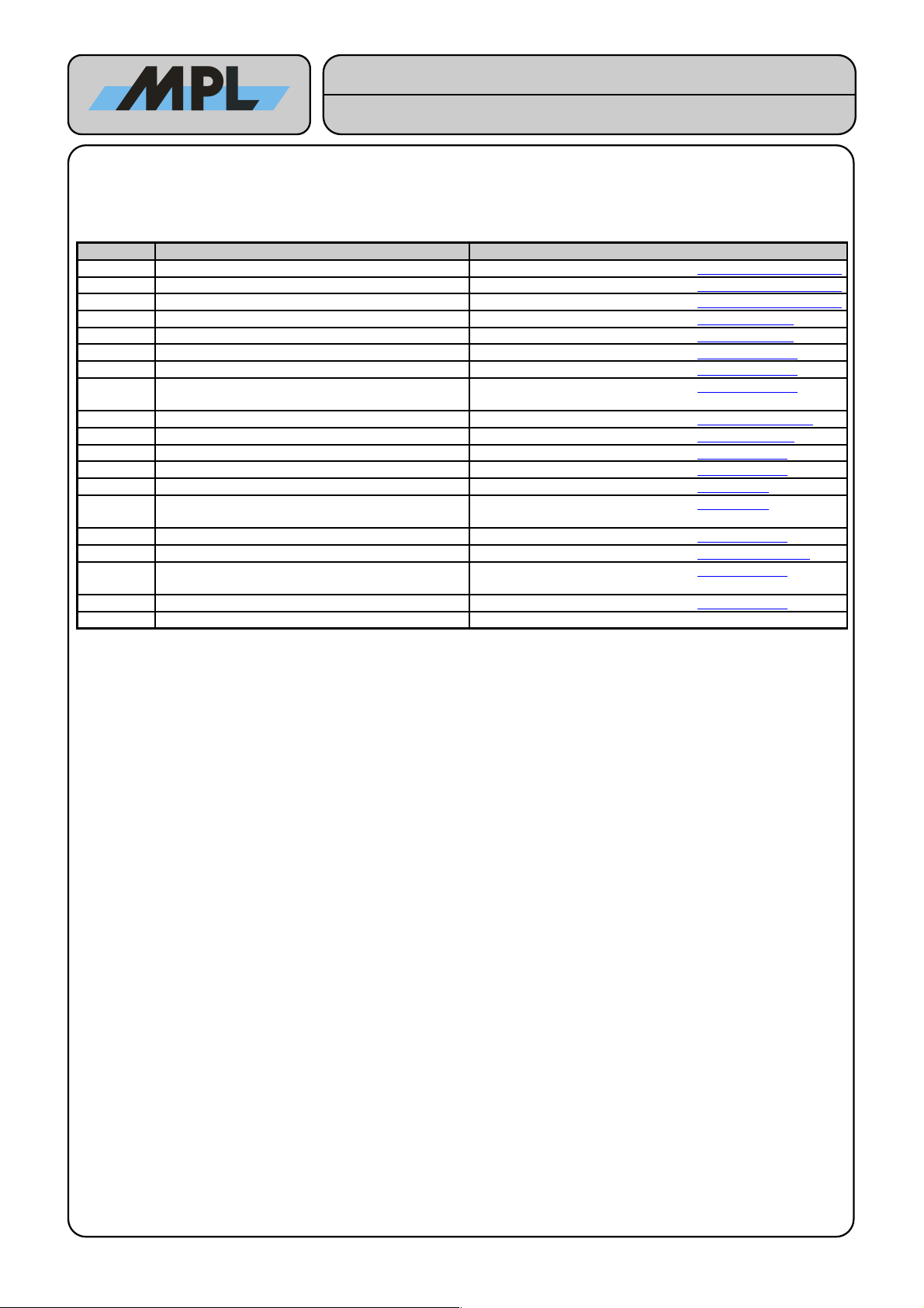
1.8 ORDERING INFORMATION
The table below gives you an overview of the different PIP variants and its features:
Product Name Product Features
PIP20-1
PIP22-1
•PIP20: 1.66 GHz Core Duo L2400 with 2 MByte Level2 Cache
•PIP22: 1.5 GHz Core 2 Duo L7400 with 4 MByte Level2 Cache
•1 GByte soldered down on board DDR2-667 memory
•200 pin DDR2-667 SO-DIMM socket (up to 2GB memory)
•Two SATA ports
•One IDE Ultra DMA-100 port
•Two Gbit Ethernet ports
•One IEEE 1394b bilingual port
•Four USB 2.0 ports
•One parallel port with parallel port floppy possibility
•Two RS232 ports, optionally additional two RS232 or RS485 ports possible
•PC 104 & PC 104-PLUS interface
•One PCI-Express Mini Card Slot
•RoHS compliant
•Custom Assembly for series with 100 pieces and more
•Please contact MPL AG for further information
There are also many more options available for:
•Housing size, displays, touch, IP65
•PC 104-PLUS card -, PCI card -, PCI Express Mini Card -, PC-Card -, CF card- and PMC
module extensions
•CDROM
•UPS
•Extended input voltage power module
•Extended temperature
•etc.
Please have a look at our homepage for this on www.mpl.ch t2400.html or contact MPL AG for
further information.
2010 by MPL AG 11 MEH-10126-201 Rev. D
High-Tech • Made in Switzerland
PIP20 / PIP22
Tec nical Reference Manual

2 SPECIFICATION
This chapter provides an overview of the PIP20 product and its features
2.1 ELECTRICAL
2.1.1 PROCESSOR
•Low voltage 1.66 GHz Intel Core Duo processor L2400 with 2 MByte Level2 Cache in 65 nm technology
•Or Low voltage 1.5 GHz Intel Core Duo processor L7400 with 4 MByte Level2 Cache in 65 nm technology
•Enhanced Intel SpeedStep technology
•Supports catastrophic thermal protection
2.1.2 CHIPSET
•Intel 945GM & ICH7-MDH
•667 MHz source-synchronous Front Side Bus
•Supports ACPI-defined power states S1 (Stop Grant), S3 (Suspend to RAM), S4 (Suspend to Disk), S5 (Soft
Off)
•Intel DMI interface and PCI-Express bus for high data bandwidth
2.1.3 BIOS ROM
•1 MByte Firmware Hub
•Easy BIOS update
•BIOS source owned by MPL AG
2.1.4 MEMORY
•Dual channel DDR2-667 (2x PC2-5300) memory
•Up to 1 GByte on board
•200 pin SO-DIMM slot supports up to 2 GByte memory
2.1.5 RTC
•Backed with field changeable on board battery
2.1.6 PC/104-PLUS INTERFACE
•8 16 bit memory and I O PC 104 interface
•PC 104 DMA and ISA Master not supported
•32 bit PC 104-PLUS interface
•Up to 4 PC 104-PLUS bus masters (PC 104-PLUS Spec. Rev. 2.2)
2.1.7 GRAPHICS
•Intel Generation 3.5 Integrated Graphics Engine and Intel Graphics Media Accelerator 950 (GMA950)
•250 MHz graphics core with 2D and 3D engine and up to 224 MByte Graphics Memory
•Dual Pipe independent display functionality
•400 MHz, 24 bit RAMDAC
•LVDS port on 1 mm header supports up to 1600 x 1200 (UXGA)
•Digital Video Interface on DVI-I connector supports up to 1600 x 1200 and 1920 x 1200 (reduced blanking)
•Analog Video Interface on DVI-I connector supports up to 2048 x 1536 (QXGA) @ 75 Hz
•DVI-I connector is ESD protected
2.1.8 USB
•6 Ports with 1.5 12 480 MBit s (4 external, 2 internal)
•Supports USB keyboards and mice as legacy devices
•ESD protected
2.1.9 SERIAL PORTS
•2 full modem serial RS232 ports, 16C550 compatible
2010 by MPL AG 12 MEH-10126-201 Rev. D
High-Tech • Made in Switzerland
PIP20 / PIP22
Tec nical Reference Manual

•2 ports can be equipped either with RS232 or with RS485 RS422 interface modules (both optional). Please
refer to the chapter below for more information.
•COM1 - COM4 with 16 byte FIFO
•Selectable transfer rates up to 230.4 kBaud
•Available on standard DB9 connectors
•ESD protected
2.1.10 RS485/RS422 INTERFACE MODULES (OPTIONAL)
•2 galvanically isolated half- or full-duplex ports
•Automatic RS485 half-duplex direction control
•Selectable transfer rates up to 230.4 kBaud
•Available on standard DB9 connectors
•ESD protected
2.1.11 PARALLEL PORT
•IEEE1284 compliant, SPP, EPP1.7, EPP1.9, ECP mode support
•Configurable as LPT1, LPT2, LPT3
•Floppy disk on parallel port mode (on DB25 connector J3), with floppy power available on connector
•ESD protected
2.1.12 IDE PORTS
•1 port on 44 pin connectors with Master Slave capability
•Support of Ultra DMA-100 Mode
2.1.13 SATA-I PORTS
•2 ports on standard SATA connectors
•Data transfer rates up to 150 MByte s
•Support of RAID 0 and RAID 1
2.1.14 FLOPPY DISK
•Available over parallel port connector for an external floppy
2.1.15 FIREWIRE 1394B
•TI TSB82AA2 Controller
•1 port on 1394b bilingual connector and 1 port on internal header supports up to 800 MBit s
•Provides input power over Polyfuses to the FireWire connectors
•ESD protected
2.1.16 ETHERNET
•2 Intel 82573L 10M 100M 1G Bit s Ethernet controllers
•Wake On LAN support
•Connected over PCI-Express bus
•ESD protected
2.1.17 KEYBOARD / MOUSE
•Available on one 6 pin mini DIN connector (PS 2)
•ESD protected
2.1.18 AC’97 AUDIO CONTROLLER
•AC’97 2.2 compliant
•AC’97 function available over optional extension PCB called SoundPAN-1. With internal speaker and
external, on the user slot available, line IN, line OUT, headphone and microphone interfaces.
2.1.19 INDICATORS
•Power LED (green: power ok, green yellow blinking: CPU > 100 °C, green blinking: S3 state)
•Reset LED (red : reset state, red blinking: power fail)
2010 by MPL AG 13 MEH-10126-201 Rev. D
High-Tech • Made in Switzerland
PIP20 / PIP22
Tec nical Reference Manual

•HDD LED (green: IDE and or SATA activity)
•1394b LED (yellow: FireWire Device connected)
•LAN1 Activity LED (green : link established, green blinking: activity)
•LAN1 Speed LED (dark: 10MBit s, green: 100MBit s, yellow: 1GBit s)
•2 user-programmable LED’s (yellow)
•Wireless WAN LED (green : Wide Area Network module powered and ready, green slow blinking: searching,
green intermittent blinking: activity)
•Wireless LAN LED (green : Local Area Network module powered and ready, green slow blinking: searching,
green intermittent blinking: activity)
•Wireless PAN LED (green : Personal Area Network module powered and ready, green intermittent blinking:
activity)
•LAN2 Activity LED (green : link established, green blinking: activity)
•LAN2 Speed LED (dark: 10MBit s, green: 100MBit s, yellow: 1GBit s)
2.1.20 RESET BUTTON, POWER BUTTON
•Connection for an external remote reset and remote power button
•Power Button on case top
•ESD protected
2.1.21 HARDWARE WATCHDOG TIMER
•Implemented in Intels ICH7-MDH
2.1.22 TEMPERATURE SENSORS
•Monitors the CPU, the on board memory and the PCB board temperature
2.1.23 VOLTAGE SENSORS
•Monitors the CPU core, 2.5V, 5V and 12V board voltages
2.1.24 SPECIALTIES
•UPS function (optional)
•Input voltage up to 48V (optional)
•Galvanic isolated Power Supply input (optional)
•CAN Extension (optional)
2010 by MPL AG 14 MEH-10126-201 Rev. D
High-Tech • Made in Switzerland
PIP20 / PIP22
Tec nical Reference Manual

2.2 PHYSICAL
2.2.1 HOUSING
•Aluminum
•No ventilation holes
•Easily mountable on 35 mm DIN rail
2.2.2 FORM FACTOR
•Length: 270 mm (10.63 inch) standard version
440 mm (17.32 inch) Wintergarden version with PCI slot extension
•Width: 162 mm (6.38 inch)
•Height: 62.0 mm (2.44 inch) standard version
82.5 mm (3.25 inch)
120 mm (4.72 inch)
2.2.3 WEIGHT
•Typically 2.2 kg (4.85 lb.) (Standard housing, equipped with internal 2.5 inch HDD and CDROM)
2.3 POWER
2.3.1 POWER SUPPLY
•High-efficiency 6 channel switching regulator module
•ATX behavior (Soft off)
•Power input is ESD protected
2.3.2 FUSE
•5 x 20 mm, 3.15 AT
•Field changeable
2.3.3 RTC BATTERY
•Renata CR2032 3V Lithium Coin Cell Battery (20.0 x 3.2 mm)
•3 V 230 mAh
•Field changeable
2.3.4 INPUT POWER
•8 VDC .. 28 VDC
•Optional 20 VDC .. 48 VDC
•The power usage can change in a wide range according to the amount of installed memory and also
according to the needed CPU, memory, graphics and interfaces usage, as examples:
•0.6 W (ATX S5 power state (Soft Off), without Ethernet link)
•1.2 W (ATX S5 power state (Soft Off), with link on both Ethernet interfaces)
•15 W (2 GB DDRII-667 SDRAM, HD, Windows XP Desktop Screen, 1x GBit Ethernet).
•28 W (2 GB DDRII-667 SDRAM, HD, Windows XP with SiSoft Sandra Burn-In Tool, 1x GBit Ethernet).
2.4 ENVIRONMENT
2.4.1 TEMPERATURE RANGE
•Storage temperature range -45°C to 85°C (-49°F to +185°F).
•Operating temperature range -20°C to +60°C (-4°F to +140°F) (with full CPU, 3D video and memory usage,
mounted on a DIN rail with freely natural convection).
•Extended operating temperature range available (screening).
2.4.2 RELATIVE HUMIDITY
•5% to 95% non-condensing
2010 by MPL AG 15 MEH-10126-201 Rev. D
High-Tech • Made in Switzerland
PIP20 / PIP22
Tec nical Reference Manual
3 HARDWARE REFERENCE
3.1 HOUSING DIMENSIONS
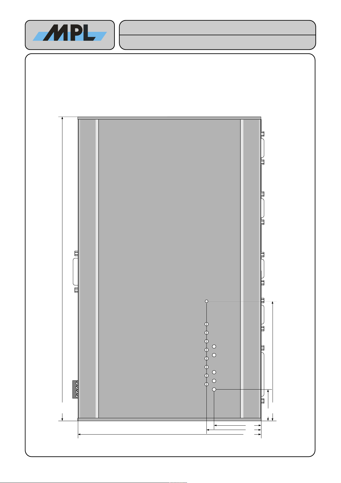
3.1.1 TOP VIEW
SIDE VIEW 4
SIDE VIEW 1
SIDE VIEW 2
270.0
48.3
162.1
106.2
27.9
SIDE VIEW 3
41.6
Figure 1: PIP2x Housing Top View (Without Cover Foil)
2010 by MPL AG 16 MEH-10126-201 Rev. D
High-Tech • Made in Switzerland
PIP20 / PIP22
Tec nical Reference Manual
3.1.2 BOTTOM VIEW
SIDE VIEW 3
SIDE VIEW 2
SIDE VIEW 1
SIDE VIEW 4
270.0
185.0
165.0
105.0
85.0
59.5
81.1
109.5
162.1
Figure 2: PIP2x Housing Bottom View
2010 by MPL AG 17 MEH-10126-201 Rev. D
High-Tech • Made in Switzerland
PIP20 / PIP22
Tec nical Reference Manual
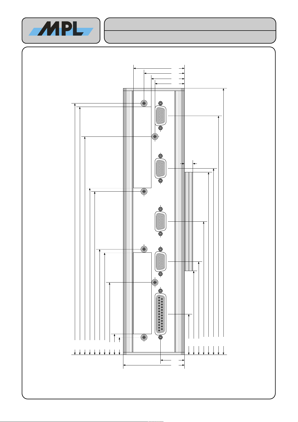
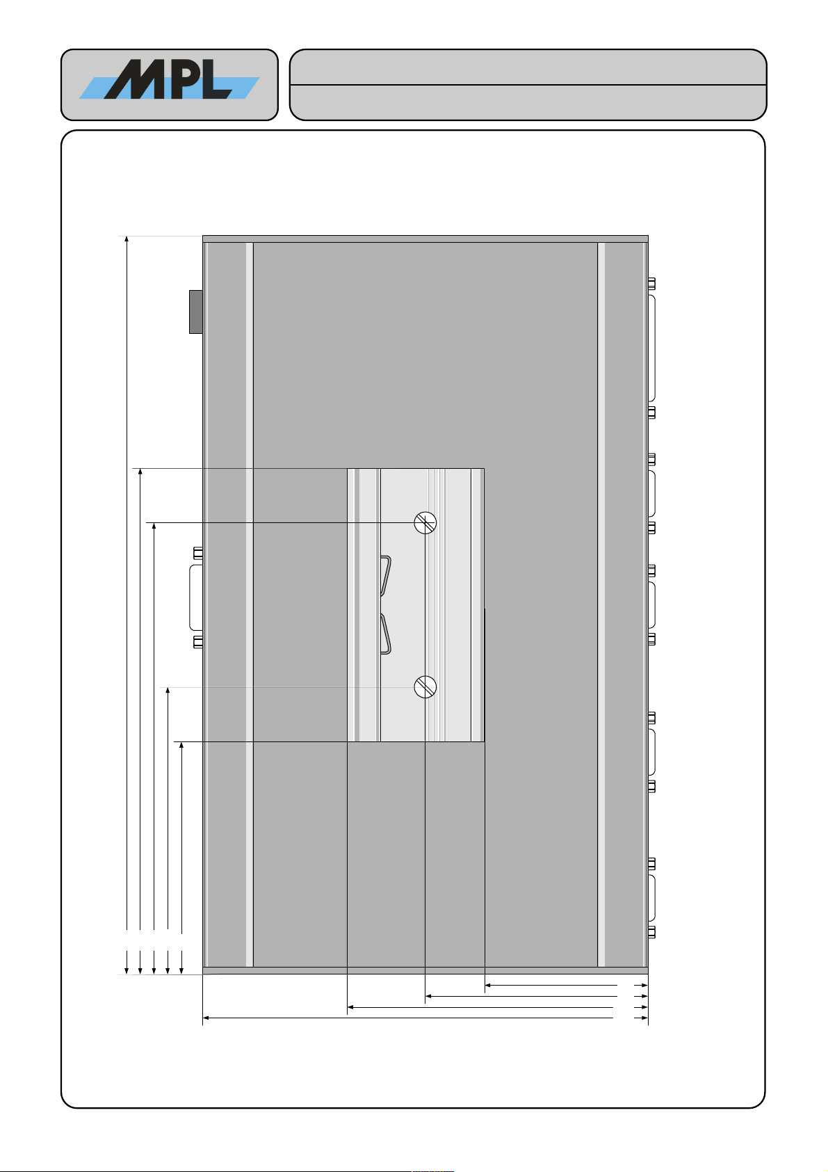
3.1.3 SIDE VIEW 1
62.0
SIDE VIEW 4
BOTTOM VIEW
TOP VIEW
270.0
DSUB-9 DSUB-9 DSUB-9
85.0
185.0
24.3
29.9
33.7
40.9
51.7
82,3 x 18,5
82,3 x 18,5
21.2
73.3
103.4
106.9
165.4
168.9
221.0
251.1
41.2
94.3
135.0
188.8
242.1
254.6
(82.5), [120.0]
SIDE VIEW 3
(72.2), [109.7]
User Slot 1 User Slot 2
DSUB-25
17.7
8.5
Figure 3: PIP2x Housing Side View 1
Note: Use the numbers in parentheses for the higher versions (82.5 mm) [120 mm].
2010 by MPL AG 18 MEH-10126-201 Rev. D
High-Tech • Made in Switzerland
PIP20 / PIP22
Tec nical Reference Manual
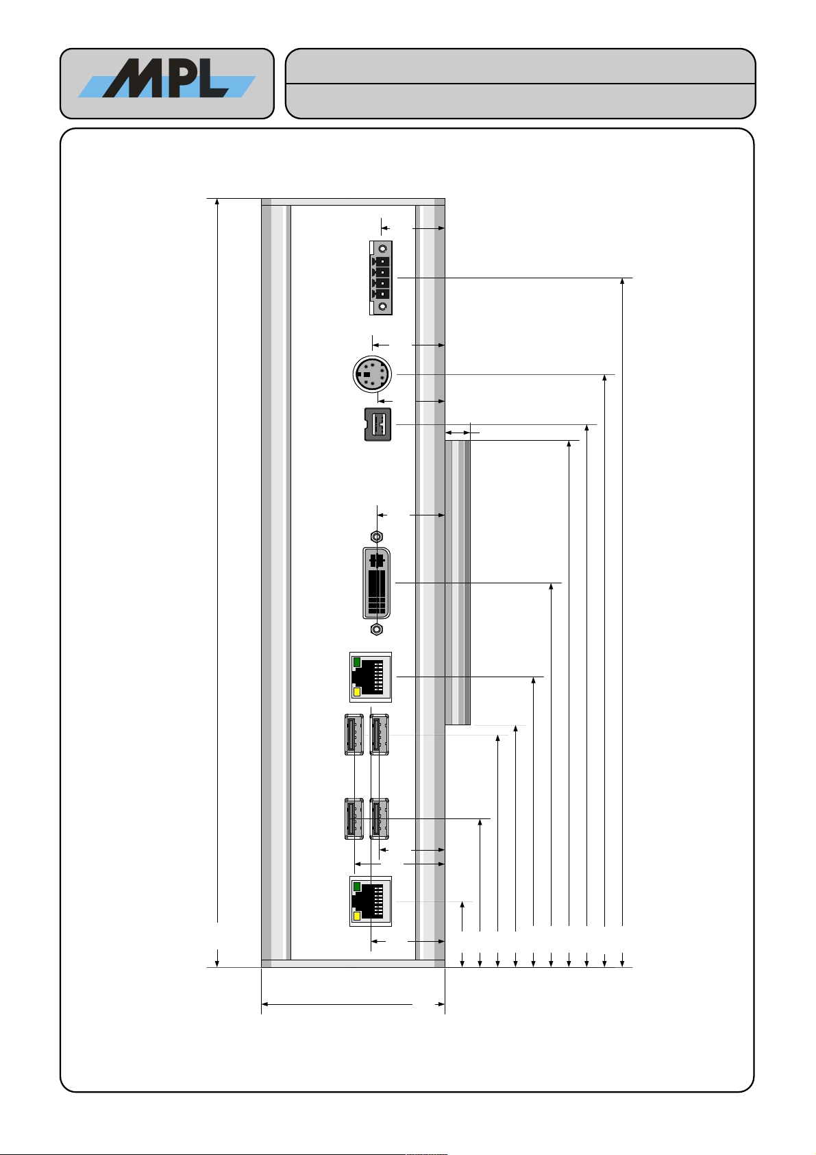
3.1.4 SIDE VIEW 2
SIDE VIEW 4
TOP VIEW
BOTTOM VIEW
62.0
85.0
185.0
270.0
8.5
23.2
81.6
134.9
190.6
208.2
21.6
SIDE VIEW 3
(82.5), [120.0]
25.0
23.0
24.5
242.1
30.6
22.1
52.1
101.9
22.6
Figure 4: PIP2x Housing Side View 2
Note: Use the numbers in parentheses for the higher versions (82.5 mm) [120 mm].
2010 by MPL AG 19 MEH-10126-201 Rev. D
High-Tech • Made in Switzerland
PIP20 / PIP22
Tec nical Reference Manual
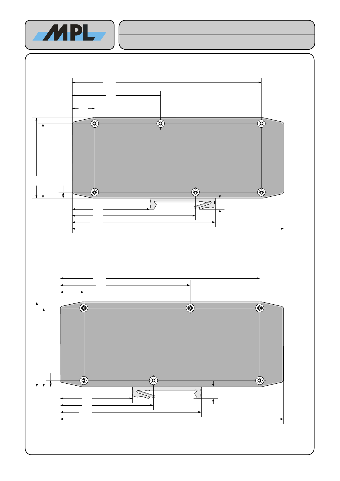
3.1.5 SIDE VIEW 3
Figure 5: PIP2x Housing Side View 3
Note: Use the numbers in parentheses for the higher versions (82.5 mm) [120 mm].
3.1.6 SIDE VIEW 4
Figure 6: PIP2x Housing Side View 4
Note: Use the numbers in parentheses for the higher versions (82.5 mm) [120 mm].
2010 by MPL AG 20 MEH-10126-201 Rev. D
High-Tech • Made in Switzerland
PIP20 / PIP22
Tec nical Reference Manual
SIDE VIEW 2
BOTTOM VIEW
SIDE VIEW 1
109.5
59.5
162,1
62,0
67,7
144,9
17,2
94,4
4,6
57,4
8,5
(82.5), [120.0]
(77.9), [115.4]
TOP VIEW
TOP VIEW
SIDE VIEW 1
BOTTOM VIEW
SIDE VIEW 2
102.5
52.5
162,1
62,0
94,4
144,9
17,2
67,7
4,6
57,4
8,5
(82.5), [120.0]
(77.9), [115.4]
This manual suits for next models
1
Table of contents
Other MPL Industrial PC manuals


