OPERATING MANUAL
Alarm System TG 400
Order No. 80504
Introduction
The alarm system TG 400 is used for the protection
against unauthorized use of the vehicle in which the
alarm system is installed.
The alarm system can be operated using one of the two
remote controls.
If the alarm system is armed, jerky vehicle movement
triggers the built-in vibration sensor initially only with
a pre-alarm. A short warning tone sounds. If another
vibration is detected within 30 seconds, a loud siren will
be activated for about 25 seconds.
A 9V battery in the casing of the alarm system serves
as an emergency power supply for the alarm in case the
power supply to the 12V vehicle battery is disconnected.
Notes
Warning
In order to prevent the risk of a short circuit or
malfunctions, you should protect the device against
moisture. It is forbidden to open the device! (Except
the battery compartment.)
Waste Electrical and Electronic Equipment
Ordinance
All electrical and electronic equipment must be
disposed of separately from regular household
waste at the designated places. If there is a symbol
showing a crossed out waste bin on a product,
this product is subject to the European Directive
2002/96/EC. The appropriate disposal and separate
collection of waste equipment serve to prevent
potential damage to the environment and to health.
They are a prerequisite for the re-use and recycling
of used electrical and electronic equipment. Further
information on the disposal of your waste equip-
ment is available from your municipality, your waste
disposal company or the specialized dealer who
sold you the product.
Scope of Supply
The scope of supply for the Alarm System TG
400 includes:
1 x central unit with integrated siren
2 x remote controls
1 x 9V battery
1 x set of connection cables
1 x operating manual
Choosing the Place of Installation
• Choose a place in your vehicle which is splash-
proof and inaccessible to unauthorized persons for
the installation of the central unit.
• Avoid using places with the following sources of
interference:
- Splashing/condensation water
- Strong vibrations
- Heat (motor, exhaust, etc.)
- Proximity to high voltage sources (e.g. ignition)
• Make sure to keep the upper side of the alarm
system free of any objects. This is where the siren
is located.
• Make sure that you can still easily reach the battery
compartment of the central unit after the installation.
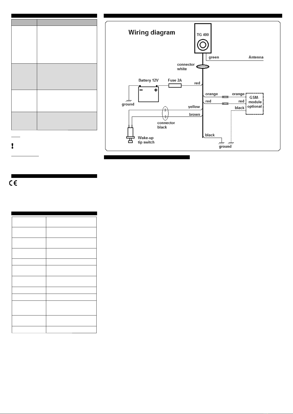
Installation
If you do not have basic knowledge in the field of elect-
ronics, have the alarm system installed and connected
in a specialist workshop.
• Disconnect the negative pole of the vehicle battery.
• Insert the 9V battery into the central unit. Polarity
must be observed.
• Fixate the central unit with the screws or the Velcro
tapes so that the cables of the cable harness point
(obliquely) downwards.
(reduces moisture penetration)
• Attach the red pushbutton of the cable harness at
a place inaccessible to unauthorized persons (drill
hole diameter 6.5 mm).
• Connect the thick red cable, which has a fuse
holder (fuse type Ø 6x30 mm, 2 A), with the positive
pole of your 12V battery.
• Connect the thick black cable to ground or the
negative pole of your 12V battery.
• Connect the white 6-pole connector (female) of the
cable harness with the white 6-pole socket (male) of
the alarm system.
• Connect the small black connector (female) of the
pushbutton with the small black socket (male) of the
cable harness.
• The green cable from the central unit is the anten-
na. It must not be cut. Lay the cable at an inacces-
sible place and so that it runs as perpendicular as
possible. Do not lay it directly to the frame or metal
objects.
• The orange and the red cables are used to connect
a GSM module from the M+S accessories program.
If you do not connect the module, roll up the cables
and insulate the ends with electrical tape.
• Lay all cables without bending them and prevent
abrasion.
• Reconnect the negative pole of the vehicle battery.
• Push the red button on the cable harness in order to
switch the alarm system to ready-to-operate.
Note:
The two thick cables (red and black) must always
be connected to ensure that the alarm system
works. The connection of the rest of the cables is
not necessary. However, some of the functions of
the alarm system will not be working if those cables
are not connected.
Insulate unused wires and connectors to prevent
malfunctions or short-circuits. In case of an incorrect
connection, the miniature fuse integrated in the fuse
holder of the cable harness can be destroyed. It must
be replaced with a fuse of the same type (Ø 6x30 mm,
2A inert) after troubleshooting.
Using the Alarm System
1. Arming the Alarm System
• Push button A “ON” on the
handheld transmitter.
• A short acoustic signal will
then play. After about 3
seconds, the alarm system
will be armed and ready.
2. Disarming the Alarm
System:
• Push button B “OFF” on
the handheld transmitter.
• Two short acoustic signals
will then play. The alarm
system is disarmed.
3. Triggering the
Panic Alarm :
• Push button C “PANIC” on
the handheld transmitter.
èThe alarm signal will play for about 6 seconds.
• Before the end of the maximum alarm duration, the
alarm signal can be switched off by pushing the
button B “OFF”.
4. Activating the “Power Save Mode“:
• Disarm the alarm system by pushing button B
“OFF” on the handheld transmitter
• Push the buttons B and D on the handheld transmit-
ter simultaneously. èThree short acoustic signals
will then play. The alarm system is now in the
“Power Save Mode” and does not consume power.
The alarm function is switched off!
• Check the “Power Save Mode” by pushing button
A “ON” on the handheld transmitter èThere must
be no acoustic signal. The alarm system can not be
armed anymore.
5. Waking up from the “Power Save Mode“:
• Push the red button on the cable harness of the
alarm system. èTwo short acoustic signals will
then play.
• Check the waking up from the “Power Save Mode”
by pushing button A “ON” on the handheld transmit-
ter èThere must be one acoustic signal. The alarm
system is now armed.
Overview of the Alarm System’s Power
Consumption
Mode Description Power consumption
Alarm sys-
tem armed
The device is
switched ON
and responds to
all transmitted
commands.
Theft protection
is switched ON.
approx. 4 mA
The vehicle should
be driven within a
period of 2 weeks
or be connected to
a battery charging
device. *
Alarm
system
disarmed
The device is
switched ON
and responds to
all transmitted
commands.
Theft protection
is switched OFF.
approx. 4 mA
The vehicle should
be driven within a
period of 2 weeks
or be connected to
a battery charging
device. *
Power
Save Mode
The device is
switched OFF
and does not
respond to
transmitted com-
mands. Sabota-
ge protection is
switched OFF.
0 mA
The vehicle can
stay parked during
winter.
*Period depends on the battery capacity
Note:
Please note that other electrical users (e.g. car
clock or computer) can also drain the battery. Under
these circumstances, the time until battery depletion
can be significantly shorter!
Adjusting the Sensitivity
Note:
• Adjusting the sensitivity of the alarm system is
carried out by transmitting commands from one of
the two remote controls to the central unit.
• The sensitivity can be adjusted at 8 levels.
• The default setting is level 8 = highest sensitivity
• Disarm the alarm system by pushing button B
“OFF” on the handheld transmitter.
• Push the buttons A and B on the handheld transmit-
ter simultaneously. èTwo short acoustic signals
will then play.
• Push button A on the handheld transmitter within
5 seconds. èTwo short acoustic signals will then
play. This means that the sensitivity is set to level 8,
the highest level.
• Push button A again within 5 seconds and level
7, the next lower level of sensitivity, will be set. è
After every push, a short acoustic signal is played
for confirmation.
• Push button A within 5 seconds as often as you
need to set the desired sensitivity level.
• Save the desired sensitivity by pushing button B on
the handheld transmitter or wait 5 seconds after the
last entry. The last level will then automatically be
saved. èTwo short acoustic signals will be played
for confirmation.
Note:
• If you adjusted the sensitivity to the lowest level 1
(=minimum sensitivity) and push button A again,
the sensitivity will be readjusted to the highest level
8 (=maximum sensitivity). èTwo short acoustic
signals will be played for confirmation.
• If both the 12V power supply to the central unit and
the connection to the 9V battery are interrupted, the
saved sensitivity level will be erased. The saved
sensitivity level will also be erased when the „Power
Save Mode“ has been activated. In both cases, the
sensitivity must be reprogrammed afterwards!
Battery Change
In order to ensure the protection of your alarm system
from manipulation, we recommend that you change the
9V battery once a year.