MPS MEZS7-2SBoostCharger User manual
MEZS7-2SBoostCharger
2-Cell Li-Ion/Li-Polymer Switching
Charger for 5V Input & Integrated
Cell balance Solution Module
MEZS7-2SBoostCharger Rev. 1.1 www.MonolithicPower.com 1
8/20/2020 MPS Proprietary Information. Patent Protected. Unauthorized Photocopy and Duplication Prohibited.
© 2020 MPS. All Rights Reserved.
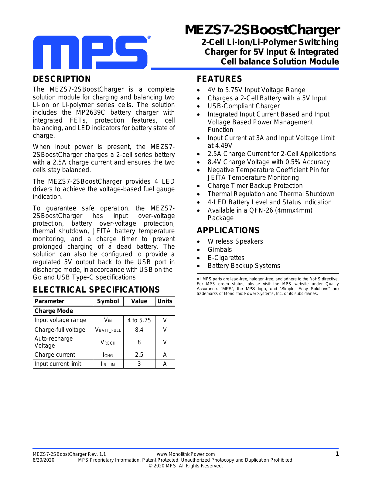
DESCRIPTION
The MEZS7-2SBoostCharger is a complete
solution module for charging and balancing two
Li-ion or Li-polymer series cells. The solution
includes the MP2639C battery charger with
integrated FETs, protection features, cell
balancing, and LED indicatorsfor battery state of
charge.
When input power is present, the MEZS7-
2SBoostCharger charges a 2-cell series battery
with a 2.5A charge current and ensures the two
cells stay balanced.
The MEZS7-2SBoostCharger provides 4 LED
drivers to achieve the voltage-based fuel gauge
indication.
To guarantee safe operation, the MEZS7-
2SBoostCharger has input over-voltage
protection, battery over-voltage protection,
thermal shutdown, JEITA battery temperature
monitoring, and a charge timer to prevent
prolonged charging of a dead battery. The
solution can also be configured to provide a
regulated 5V output back to the USB port in
discharge mode, in accordance with USB onthe-
Go and USB Type-C specifications.
ELECTRICAL SPECIFICATIONS
Parameter
Symbol
Value
Units
Charge Mode
Input voltage range
VIN
4 to 5.75
V
Charge-full voltage
VBATT_FULL
8.4
V
Auto-recharge
Voltage
VRECH
8
V
Charge current
ICHG
2.5
A
Input current limit
IIN_LIM
3
A
FEATURES
4V to 5.75V Input Voltage Range
Charges a 2-Cell Battery with a 5V Input
USB-Compliant Charger
Integrated Input Current Based and Input
Voltage Based Power Management
Function
Input Current at 3A and Input Voltage Limit
at 4.49V
2.5A Charge Current for 2-Cell Applications
8.4V Charge Voltage with 0.5% Accuracy
Negative Temperature Coefficient Pin for
JEITA Temperature Monitoring
Charge Timer Backup Protection
Thermal Regulation and Thermal Shutdown
4-LED Battery Level and Status Indication
Available in a QFN-26 (4mmx4mm)
Package
APPLICATIONS
Wireless Speakers
Gimbals
E-Cigarettes
Battery Backup Systems
All MPS parts are lead-free, halogen-free, and adhere to the RoHS directive.
For MPS green status, please visit the MPS website under Quality
Assurance. “MPS”, the MPS logo, and “Simple, Easy Solutions” are
trademarks of Monolithic Power Systems, Inc. or its subsidiaries.

MEZS7-2SBOOST CHARGER –MP2639C SOLUTION MODULE
MEZS7-2SBoostCharger Rev. 1.1 www.MonolithicPower.com 2
8/20/2020 MPS Proprietary Information. Patent Protected. Unauthorized Photocopy and Duplication Prohibited.
© 2020 MPS. All Rights Reserved.
MEZS7-2SBOOST CHARGER SOLUTION MODULE
(LxWxH) 3cmx2.8cmx0.16cm
Board Number
MPS IC Number
MEZS7-2SBoostCharger
MP2639CGR

MEZS7-2SBOOST CHARGER –MP2639C SOLUTION MODULE
MEZS7-2SBoostCharger Rev. 1.1 www.MonolithicPower.com 3
8/20/2020 MPS Proprietary Information. Patent Protected. Unauthorized Photocopy and Duplication Prohibited.
© 2020 MPS. All Rights Reserved.
QUICK START GUIDE
This solution module is for the MP2639C, a flexible switch-mode battery charging management device
for a 2-cell series Li-ion and Li-polymer battery pack used in a wide range of portable applications through
the boost converter from VL to VH.
The solution module’s layout accommodates most commonly used capacitors. The default function of
this solution module is preset to charge mode, and the charge-full voltage is preset to 8.4V for a 2-cell
series Li-ion battery.
Charge Mode Setting
1. Input Current Limit
An input current limit can be set slightly below the input source’s maximum current rating. When the
input current reaches this limit, the charge current decreases to keep the input current constant at the
limit value to initially power the system. The resistor connected to the ILIM pin (RILIM) programs this
limit. To set the input current limit at 3A, use an RILIM of 71.5kΩ. Calculate IINLIMT using Equation (1):
640
3
INLIMT ILIM
k
IR
(1)
2. Charge Current
The charge current can be programmed via RISET. Determine the charge current using Equation (2):
640
3
CHG ISET
k
IR
(2)
For a 2.5A charge current, the given RISET is 85.3kΩ.
3. Input Voltage Limit
The input voltage clamp threshold is programmable by the VLIM pin. The internal reference of the
input voltage loop is 1.2V. Determine the input voltage clamp limit using Equation (3):
34
INLIMT 4
RR
V 1.2 R
(3)
Where R3 = 27.4kΩ, R4 = 10kΩ, the input voltage clamp value is 4.49V.

MEZS7-2SBOOST CHARGER –MP2639C SOLUTION MODULE
MEZS7-2SBoostCharger Rev. 1.1 www.MonolithicPower.com 4
8/20/2020 MPS Proprietary Information. Patent Protected. Unauthorized Photocopy and Duplication Prohibited.
© 2020 MPS. All Rights Reserved.
EQUIPMENT REQUIREMENTS
Evaluation requires the following equipment:
1. A USB cable with an adapter or any USB port with load capability (for the charge input) can be used
for the solution module. If a certain operation state cannot be tested, an external wire can be added
to connect a power source with 6V/3A capability.
2. A battery simulator or 2-cell battery pack. The battery simulator’s output rating should be greater than
9V/7.0A. When using a real battery pack, review all precautions in the battery manufacturer’s
datasheet and ensure the charger’s setting does not exceed the battery’s absolute maximum
specifications.
3. An oscilloscope with a single voltage probe and a single current probe.
4. A multi-meter.
Charge Function
1. Attach the positive (VH) and negative ends (PGND) of the board to the “+” and “-” terminals of the
battery or battery simulator, respectively. If using a battery simulator, preset the voltage to 7.6V
(typical value for 2-cell) first.
2. Attach the USB cable to the USB1 port.
U1
MAIN CIRCUIT
VH
AGND VCC
NTCMID
IB
CHG
ACOK
USB1
MPS
2-Cell Battery
Pack or
Simulator
Adapter,
USB Port
U2
CHGACOK
GND
MEZS7-2SBoostCharger
Figure 1: Set-Up for Charge Mode from USB Cable
MEZS7-2SBOOST CHARGER –MP2639C SOLUTION MODULE
MEZS7-2SBoostCharger Rev. 1.1 www.MonolithicPower.com 5
8/20/2020 MPS Proprietary Information. Patent Protected. Unauthorized Photocopy and Duplication Prohibited.
© 2020 MPS. All Rights Reserved.
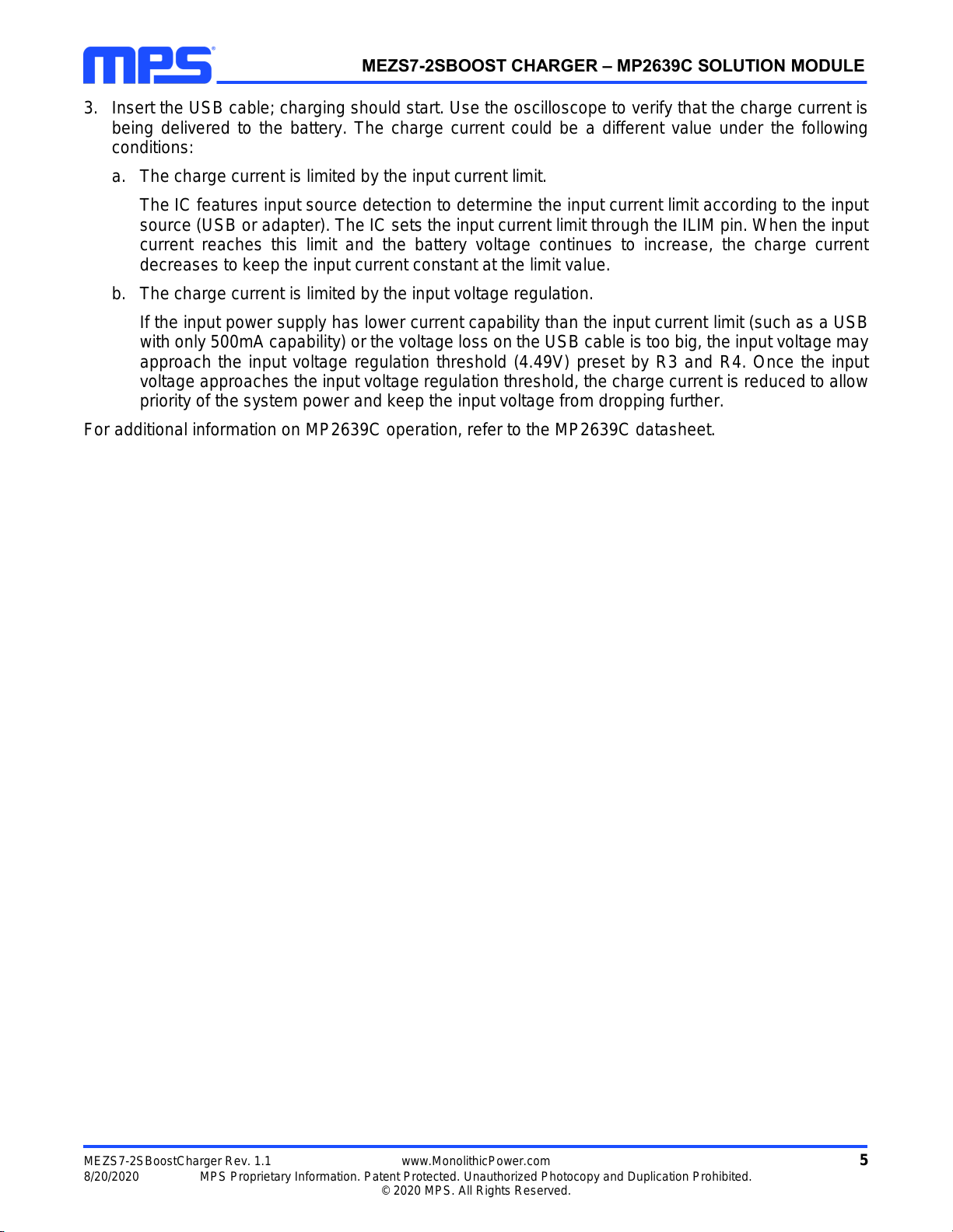
3. Insert the USB cable; charging should start. Use the oscilloscope to verify that the charge current is
being delivered to the battery. The charge current could be a different value under the following
conditions:
a. The charge current is limited by the input current limit.
The IC features input source detection to determine the input current limit according to the input
source (USB or adapter). The IC sets the input current limit through the ILIM pin. When the input
current reaches this limit and the battery voltage continues to increase, the charge current
decreases to keep the input current constant at the limit value.
b. The charge current is limited by the input voltage regulation.
If the input power supply has lower current capability than the input current limit (such as a USB
with only 500mA capability) or the voltage loss on the USB cable is too big, the input voltage may
approach the input voltage regulation threshold (4.49V) preset by R3 and R4. Once the input
voltage approaches the input voltage regulation threshold, the charge current is reduced to allow
priority of the system power and keep the input voltage from dropping further.
For additional information on MP2639C operation, refer to the MP2639C datasheet.

MEZS7-2SBOOST CHARGER –MP2639C SOLUTION MODULE
MEZS7-2SBoostCharger Rev. 1.1 www.MonolithicPower.com 6
8/20/2020 MPS Proprietary Information. Patent Protected. Unauthorized Photocopy and Duplication Prohibited.
© 2020 MPS. All Rights Reserved.
SOLUTION MODULE SCHEMATIC
Figure 2: Solution Module Schematic
MEZS7-2SBOOST CHARGER –MP2639C SOLUTION MODULE
MEZS7-2SBoostCharger Rev. 1.1 www.MonolithicPower.com 7
8/20/2020 MPS Proprietary Information. Patent Protected. Unauthorized Photocopy and Duplication Prohibited.
© 2020 MPS. All Rights Reserved.
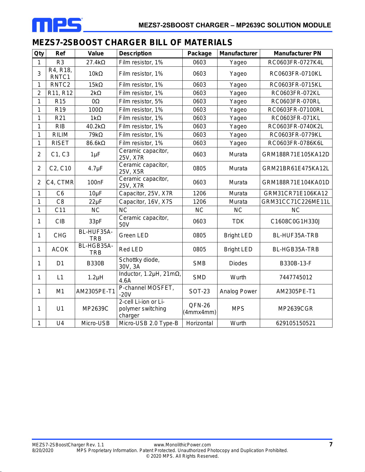
MEZS7-2SBOOST CHARGER BILL OF MATERIALS
Qty
Ref
Value
Description
Package
Manufacturer
Manufacturer PN
1
R3
27.4kΩ
Film resistor, 1%
0603
Yageo
RC0603FR-0727K4L
3
R4, R18,
RNTC1
10kΩ
Film resistor, 1%
0603
Yageo
RC0603FR-0710KL
1
RNTC2
15kΩ
Film resistor, 1%
0603
Yageo
RC0603FR-0715KL
2
R11, R12
2kΩ
Film resistor, 1%
0603
Yageo
RC0603FR-072KL
1
R15
0Ω
Film resistor, 5%
0603
Yageo
RC0603FR-070RL
1
R19
100Ω
Film resistor, 1%
0603
Yageo
RC0603FR-07100RL
1
R21
1kΩ
Film resistor, 1%
0603
Yageo
RC0603FR-071KL
1
RIB
40.2kΩ
Film resistor, 1%
0603
Yageo
RC0603FR-0740K2L
1
RILIM
79kΩ
Film resistor, 1%
0603
Yageo
RC0603FR-0779KL
1
RISET
86.6kΩ
Film resistor, 1%
0603
Yageo
RC0603FR-0786K6L
2
C1, C3
1μF
Ceramic capacitor,
25V, X7R
0603
Murata
GRM188R71E105KA12D
2
C2, C10
4.7μF
Ceramic capacitor,
25V, X5R
0805
Murata
GRM21BR61E475KA12L
2
C4, CTMR
100nF
Ceramic capacitor,
25V, X7R
0603
Murata
GRM188R71E104KA01D
1
C6
10μF
Capacitor, 25V, X7R
1206
Murata
GRM31CR71E106KA12
1
C8
22μF
Capacitor, 16V, X7S
1206
Murata
GRM31CC71C226ME11L
1
C11
NC
NC
NC
NC
NC
1
CIB
33pF
Ceramic capacitor,
50V
0603
TDK
C1608C0G1H330J
1
CHG
BL-HUF35A-
TRB
Green LED
0805
Bright LED
BL-HUF35A-TRB
1
ACOK
BL-HGB35A-
TRB
Red LED
0805
Bright LED
BL-HGB35A-TRB
1
D1
B330B
Schottky diode,
30V, 3A
SMB
Diodes
B330B-13-F
1
L1
1.2μH
Inductor, 1.2μH, 21mΩ,
4.6A
SMD
Wurth
7447745012
1
M1
AM2305PE-T1
P-channel MOSFET,
-20V
SOT-23
Analog Power
AM2305PE-T1
1
U1
MP2639C
2-cell Li-ion or Li-
polymer switching
charger
QFN-26
(4mmx4mm)
MPS
MP2639CGR
1
U4
Micro-USB
Micro-USB 2.0 Type-B
Horizontal
Wurth
629105150521

MEZS7-2SBOOST CHARGER –MP2639C SOLUTION MODULE
MEZS7-2SBoostCharger Rev. 1.1 www.MonolithicPower.com 8
8/20/2020 MPS Proprietary Information. Patent Protected. Unauthorized Photocopy and Duplication Prohibited.
© 2020 MPS. All Rights Reserved.
PCB LAYOUT
Figure 3: Top Silk Layer
Figure 4: Top Layer
Figure 5: Bottom Layer

MEZS7-2SBOOST CHARGER –MP2639C SOLUTION MODULE
Notice: The information in this document is subject to change without notice. Please contact MPS for current specifications.
Users should warrant and guarantee that third-party Intellectual Property rights are not infringed upon when integrating MPS
products into any application. MPS will not assume any legal responsibility for any said applications.
MEZS7-2SBoostCharger Rev. 1.1 www.MonolithicPower.com 9
8/20/2020 MPS Proprietary Information. Patent Protected. Unauthorized Photocopy and Duplication Prohibited.
© 2020 MPS. All Rights Reserved.
Revision History
Revision #
Revision
Date
Description
Pages
Updated
1.0
6/18/2020
Initial Release
-
1.1
8/20/2020
Replace MP2639A with MP2639C
P1-P9

Table of contents
Other MPS Batteries Charger manuals


