MPS SharedPowerBank MEZS7 User manual
MEZS7-SharedPowerBank
I2C Controlled, Single-Cell Switching
Charger with Power-Path Management
and 3.6A Boost Output Solution Module
MEZS7-SharedPowerBank Rev. 1.0 www.MonolithicPower.com 1
6/17/2020 MPS Proprietary Information. Patent Protected. Unauthorized Photocopy and Duplication Prohibited.
© 2020 MPS. All Rights Reserved.
DESCRIPTION
The MEZS7-SharedPowerBank is a complete
solution module using the MP2696A buck
charger with boost output, LED state-of-charge
indicator, and an MCU to achieve a turn-key
solution for shared power bank applications.
The MP2696A is a highly integrated, flexible,
switch-mode battery charge management and
system power path management device.
The MP2696A has three operation modes:
charge mode, boost mode, and sleep mode.
In charge mode, the solution module achieves
up to 3.6A of charge current from a 5V micro
USB input source.
In boost mode, the solution module delivers up
to 3.6A to a regulated 5V USB-A output for
charging external devices such as
smartphones. All the parameters and controls
can be easily accessed via the I2C interface.
ELECTRICAL SPECIFICATIONS
Parameter
Symbol
Value
Units
Input voltage
VIN
4 to 6
V
Input current
limit
IIN
0.1 to 3.0,
programmable
A
Charge voltage
regulation
VBATT_REG
3.6 to 4.45,
programmable
V
Charge current
ICC
Up to 3.6,
programmable
A
Output voltage
VSYS
5.05 to 5.25,
programmable
V
Output current
limit
IOLIM
2.1 to 3.6,
programmable
A
Output power
POUT
Up to 18
W
FEATURES
4V to 6V Operation Voltage Range
Up to 16V Sustainable Input Voltage
500mA to 3.6A Programmable Charge
Current
3.6V to 4.45V Programmable Charge
Regulation Voltage
100mA to 3A Programmable Input Current
Limit
Minimum Input Voltage Loop for Maximum
Adapter Power Tracking
Boost Converter with Up to 3.6A Output
Current:
oProgrammable Output Current Limit
Loop
oProgrammable Boost Output Voltage
oUSB Output Cable Compensation
oProgrammable Inductor Peak Current
Comprehensive Safety Features:
oFully Customizable JEITA Profile
oCharge Safety Timer
oInput Over-Voltage Protection
oThermal Shutdown
oSYS Over-Current and Short Protection
Analog Voltage Output IB Pin for Battery
Current Monitor
SYS Plug-In Detection
SYS No-Load Detection
SYS DP/DM Interface for BC1.2 and Non-
Standard Adapters
Status and Fault Monitoring
APPLICATIONS
Shared Power Banks
Micro-USB and USB Type-A Power Banks
Battery Backup Applications
All MPS parts are lead-free, halogen-free, and adhere to the RoHS
directive. For MPS green status, please visit the MPS website under
Quality Assurance. “MPS”, the MPS logo, and “Simple, Easy Solutions” are
trademarks of Monolithic Power Systems, Inc. or its subsidiaries.

MEZS7-SHAREDPOWERBANK –MP2696A SOLUTION MODULE
MEZS7-SharedPowerBank Rev. 1.0 www.MonolithicPower.com 2
6/17/2020 MPS Proprietary Information. Patent Protected. Unauthorized Photocopy and Duplication Prohibited.
© 2020 MPS. All Rights Reserved.
MEZS7-SHAREDPOWERBANK SOLUTION MODULE
(LxWxH) 6.35cmx6.35cmx1.2cm
Board Number
MPS IC Number
MEZS7-SharedPowerBank
MP2696AGQ-0000
MEZS7-SHAREDPOWERBANK –MP2696A SOLUTION MODULE
MEZS7-SharedPowerBank Rev. 1.0 www.MonolithicPower.com 3
6/17/2020 MPS Proprietary Information. Patent Protected. Unauthorized Photocopy and Duplication Prohibited.
© 2020 MPS. All Rights Reserved.
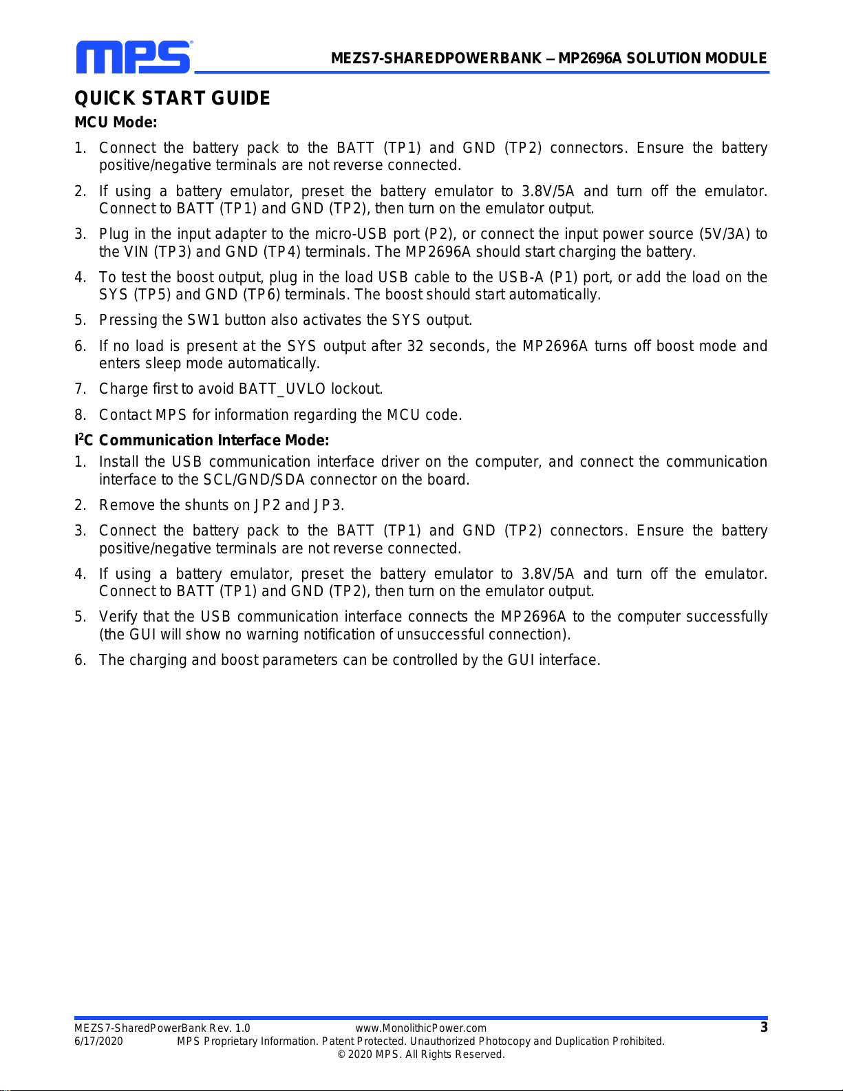
QUICK START GUIDE
MCU Mode:
1. Connect the battery pack to the BATT (TP1) and GND (TP2) connectors. Ensure the battery
positive/negative terminals are not reverse connected.
2. If using a battery emulator, preset the battery emulator to 3.8V/5A and turn off the emulator.
Connect to BATT (TP1) and GND (TP2), then turn on the emulator output.
3. Plug in the input adapter to the micro-USB port (P2), or connect the input power source (5V/3A) to
the VIN (TP3) and GND (TP4) terminals. The MP2696A should start charging the battery.
4. To test the boost output, plug in the load USB cable to the USB-A (P1) port, or add the load on the
SYS (TP5) and GND (TP6) terminals. The boost should start automatically.
5. Pressing the SW1 button also activates the SYS output.
6. If no load is present at the SYS output after 32 seconds, the MP2696A turns off boost mode and
enters sleep mode automatically.
7. Charge first to avoid BATT_UVLO lockout.
8. Contact MPS for information regarding the MCU code.
I2C Communication Interface Mode:
1. Install the USB communication interface driver on the computer, and connect the communication
interface to the SCL/GND/SDA connector on the board.
2. Remove the shunts on JP2 and JP3.
3. Connect the battery pack to the BATT (TP1) and GND (TP2) connectors. Ensure the battery
positive/negative terminals are not reverse connected.
4. If using a battery emulator, preset the battery emulator to 3.8V/5A and turn off the emulator.
Connect to BATT (TP1) and GND (TP2), then turn on the emulator output.
5. Verify that the USB communication interface connects the MP2696A to the computer successfully
(the GUI will show no warning notification of unsuccessful connection).
6. The charging and boost parameters can be controlled by the GUI interface.
MEZS7-SHAREDPOWERBANK –MP2696A SOLUTION MODULE
MEZS7-SharedPowerBank Rev. 1.0 www.MonolithicPower.com 4
6/17/2020 MPS Proprietary Information. Patent Protected. Unauthorized Photocopy and Duplication Prohibited.
© 2020 MPS. All Rights Reserved.
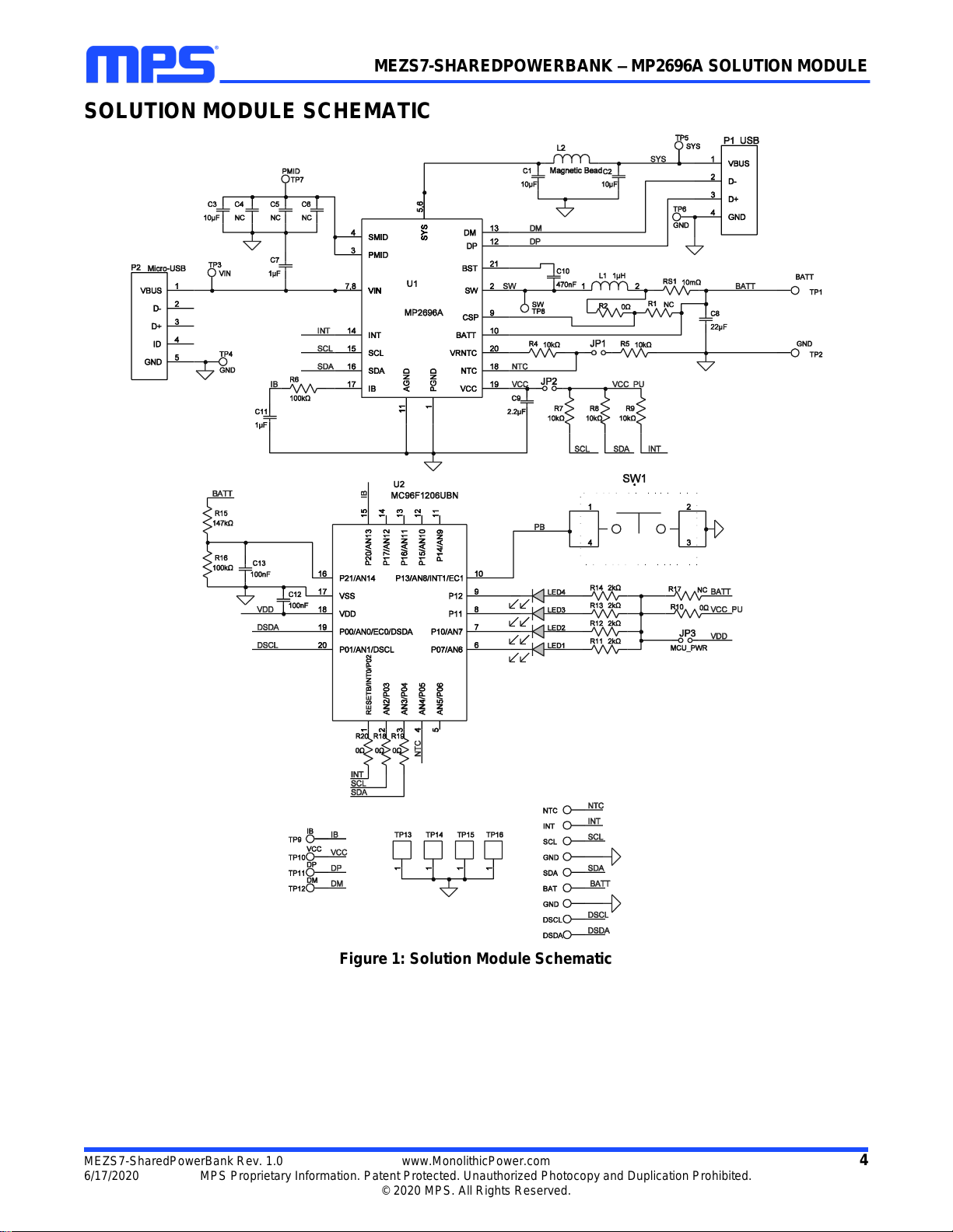
SOLUTION MODULE SCHEMATIC
Figure 1: Solution Module Schematic

MEZS7-SHAREDPOWERBANK –MP2696A SOLUTION MODULE
MEZS7-SharedPowerBank Rev. 1.0 www.MonolithicPower.com 5
6/17/2020 MPS Proprietary Information. Patent Protected. Unauthorized Photocopy and Duplication Prohibited.
© 2020 MPS. All Rights Reserved.
CONNECTIONS Table 1: Connectors
Connectors
Description
TP1/BATT
Connect to the battery pack positive terminal.
TP2/GND
Connect to the battery pack negative terminal.
TP3/VIN
Connect to the input source positive terminal.
TP4/GND
Connect to the input source negative terminal.
P2/micro-USB power input
Connect to the input power adapter.
TP5/SYS
Power bank output positive terminal.
TP6/GND
Power bank output negative terminal.
P1/USB-A power output
Power bank output USB receptacle.
SCL/SDA/GND/INT
I2C connector.
NTC
Connect to the external thermistor.
DSCL/DSDA/GND
MCU programming terminal.
Table 2: Jumpers and Shunts
Jumpers
Description
MCU Mode Default
I2C Communication
Interface Mode Default
JP1
Connect to the on-board NTC divider.
Installed
Installed
JP2
Connect the 10kΩpull-up resistors to
VCC, for SCL, SDA, and INT.
Installed
Uninstalled
JP3
MCU power from BATT.
Installed
Uninstalled

MEZS7-SHAREDPOWERBANK –MP2696A SOLUTION MODULE
MEZS7-SharedPowerBank Rev. 1.0 www.MonolithicPower.com 6
6/17/2020 MPS Proprietary Information. Patent Protected. Unauthorized Photocopy and Duplication Prohibited.
© 2020 MPS. All Rights Reserved.
MEZS7-SHAREDPOWERBANK BILL OF MATERIALS
Qty
Ref
Value
Description
Package
Manufacturer
Manufacturer P/N
2
C1, C2
10μF
Capacitor, 16V, X5R
0805
Murata
GRM21BR61C106K
E15L
1
C3
10μF
Capacitor, 16V, X5R
1206
Murata
GRM319R60J106K
E19
3
C4,C5, C6
NC
Capacitor, 16V, X5R
0805
Murata
GRM21BR61C106K
E15L
1
C7
1μF
Capacitor, 16V, X5R
0805
Murata
GRM21BR71C105K
A01
1
C8
22μF
Capacitor, 10V, X7S
0805
TDK
C2012X7S1A226M
1
C9
2.2μF
Ceramic capacitor, 10V,
X5R
0603
Murata
GRM188R71A225K
E15D
1
C10
470nF
Ceramic capacitor, 25V,
X7R, 0603
0603
TDK
C1608X7R1E474K
1
C11
1μF
Ceramic capacitor, 10V,
X7R, 0603
0603
LION
0603B105K100T
2
C12,C13
100nF
Capacitor, 16V, X7R,
0603, 100nF
0603
GCM188R71C104K
A37D
6
TP1, TP2,
TP3, TP4,
TP5, TP6
Connector, 2.0mm
DIP
2
TP7, TP8
Test point, orange
DIP
4
TP9, TP10,
TP11, TP12
Test point, white
DIP
9
DSCL,
DSDA, GND,
GND, INT,
NTC, SCL,
SDA,BAT
Connector
DIP
3
JP1, JP2,
JP3
Jumper
DIP
4
TP13, TP14,
TP15, TP16
Connector, GND
SMT
1
L1
1μH
Inductor, 1µH, 10A
SMD
Wurth
74437349010
1
L2
Bead
Magnetic bead, 3A
805
Wurth
742792063
4
LED1, LED2,
LED3, LED4
LED
Red LED
0805
BL-HUF35A-TRB
1
P1
USB-A
1
P2
Micro-USB
2
R1, R17
NC
Film resistor
5
R2, R10,
R18, R19,
R20
0Ω
Film resistor, 5%
0603
Yageo
RC0603JR-070RL
2
R4, R5
10kΩ
Film resistor, 1%
0603
Yageo
RC0603FR-0710KL
1
R6
100kΩ
Film resistor, 5%
0603
Yageo
RC0603JR-07100KL
3
R7, R8, R9
10kΩ
Film resistor, 5%
0603
Yageo
RC0603JR-0710K
4
R11, R12,
R13, R14
2kΩ
Film resistor, 5%, 1/10W
0603
LIZ
Electronics
CR0603JA0202G

MEZS7-SHAREDPOWERBANK –MP2696A SOLUTION MODULE
MEZS7-SharedPowerBank Rev. 1.0 www.MonolithicPower.com 7
6/17/2020 MPS Proprietary Information. Patent Protected. Unauthorized Photocopy and Duplication Prohibited.
© 2020 MPS. All Rights Reserved.
MEZS7-SHAREDPOWERBANK BILL OF MATERIALS (continued)
Qty
Ref
Value
Description
Package
Manufacturer
Manufacturer P/N
1
R15
147kΩ
Film resistor, 1%
0603
Yageo
RC0603FR-
07147KL
1
R16
100kΩ
Film resistor, 1%
0603
Yageo
RC0603FR-
07100KL
1
RS1
10mΩ
Film resistor, 1%, 1/4W
1206
Yageo
RL1206FR-
070R01L
1
SW1
Button
Push button, SM
4mmx10mmx1.5mm
1
U1
MP2696A
Single-cell switching
charger
QFN-21
(3mmx3mm)
MPS
MP2696AGQ-0000
1
U2
MCU
Microcontroller
QFN
(3mmx3mm)
ABOV
Semiconductor
MC96F1206UBN
MEZS7-SHAREDPOWERBANK –MP2696A SOLUTION MODULE
MEZS7-SharedPowerBank Rev. 1.0 www.MonolithicPower.com 8
6/17/2020 MPS Proprietary Information. Patent Protected. Unauthorized Photocopy and Duplication Prohibited.
© 2020 MPS. All Rights Reserved.
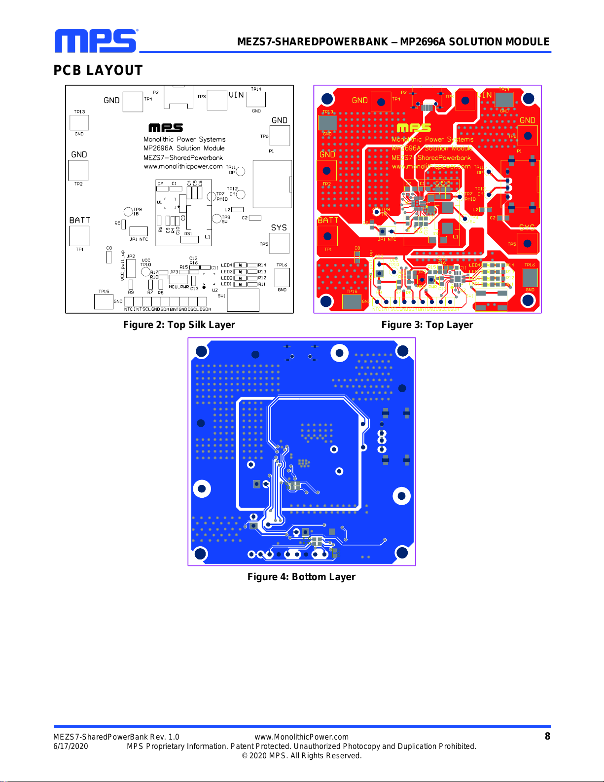
PCB LAYOUT
Figure 2: Top Silk Layer
Figure 3: Top Layer
Figure 4: Bottom Layer

MEZS7-SHAREDPOWERBANK –FAST CHARGE POWER BANK EV BOARD
Notice: The information in this document is subject to change without notice. Please contact MPS for current specifications.
Users should warrant and guarantee that third-party Intellectual Property rights are not infringed upon when integrating MPS
products into any application. MPS will not assume any legal responsibility for any said applications.
MEZS7-SharedPowerBank Rev. 1.0 www.MonolithicPower.com 9
6/17/2020 MPS Proprietary Information. Patent Protected. Unauthorized Photocopy and Duplication Prohibited.
© 2020 MPS. All Rights Reserved.
Revision History
Revision #
Revision
Date
Description
Pages
Updated
1.0
6/17/2020
Initial Release
-
Table of contents
Other MPS Batteries Charger manuals


