MPS EV2637-R-00A User manual
EV2637-R-00A
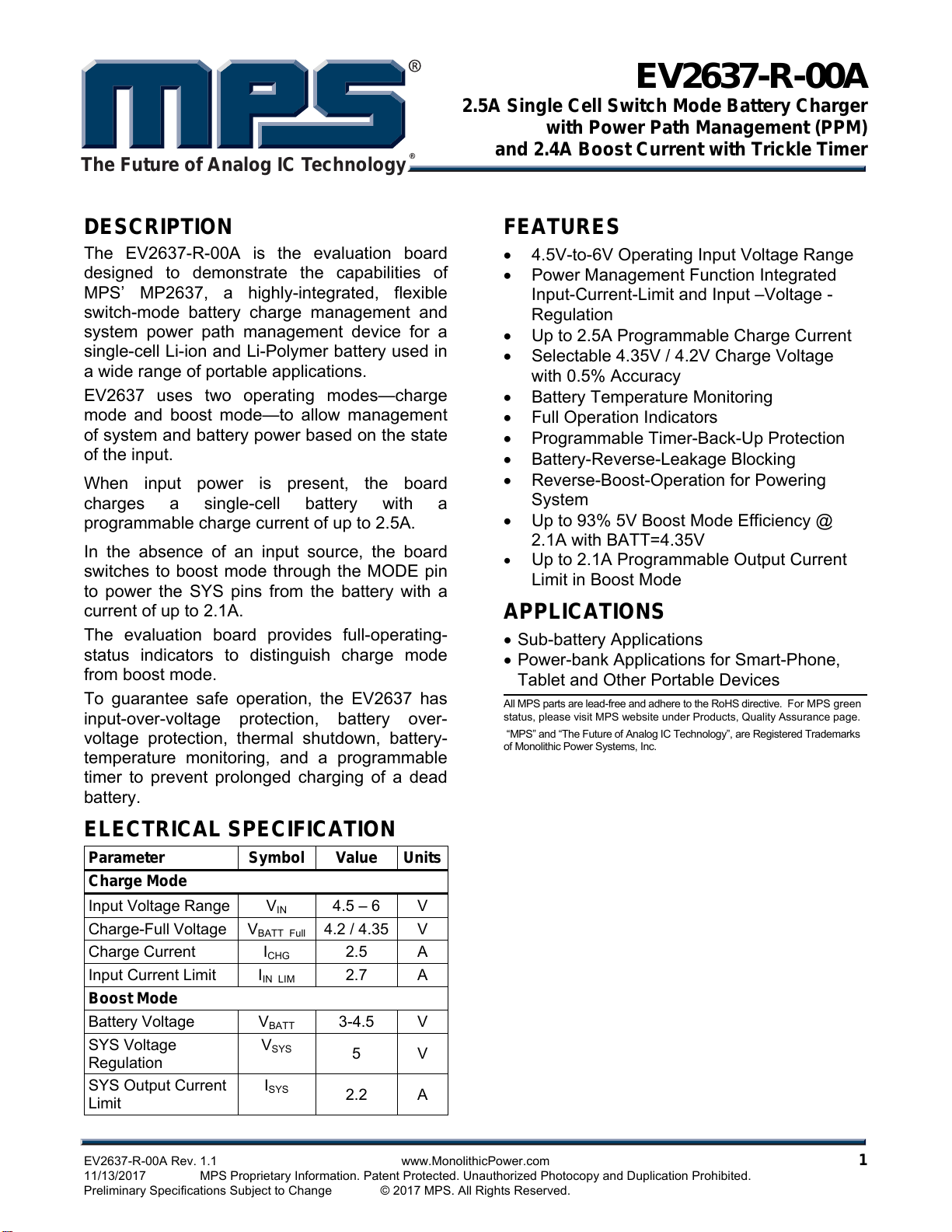
2.5A Single Cell Switch Mode Battery Charger
with Power Path Management (PPM)
and 2.4A Boost Current with Trickle Timer
EV2637-R-00A Rev. 1.1 www.MonolithicPower.com 1
11/13/2017 MPS Proprietary Information. Patent Protected. Unauthorized Photocopy and Duplication Prohibited.
Preliminary Specifications Subject to Change © 2017 MPS. All Rights Reserved.
The Future of Analog IC Technology
DESCRIPTION
The EV2637-R-00A is the evaluation board
designed to demonstrate the capabilities of
MPS’ MP2637, a highly-integrated, flexible
switch-mode battery charge management and
system power path management device for a
single-cell Li-ion and Li-Polymer battery used in
a wide range of portable applications.
EV2637 uses two operating modes—charge
mode and boost mode—to allow management
of system and battery power based on the state
of the input.
When input power is present, the board
charges a single-cell battery with a
programmable charge current of up to 2.5A.
In the absence of an input source, the board
switches to boost mode through the MODE pin
to power the SYS pins from the battery with a
current of up to 2.1A.
The evaluation board provides full-operating-
status indicators to distinguish charge mode
from boost mode.
To guarantee safe operation, the EV2637 has
input-over-voltage protection, battery over-
voltage protection, thermal shutdown, battery-
temperature monitoring, and a programmable
timer to prevent prolonged charging of a dead
battery.
ELECTRICAL SPECIFICATION
Parameter Symbol Value Units
Charge Mode
Input Voltage Range VIN 4.5 – 6 V
Charge-Full Voltage VBATT Full 4.2 / 4.35 V
Charge Current ICHG 2.5 A
Input Current Limit IIN LIM 2.7 A
Boost Mode
Battery Voltage VBATT 3-4.5 V
SYS Voltage
Regulation
VSYS 5 V
SYS Output Current
Limit
ISYS 2.2 A
FEATURES
4.5V-to-6V Operating Input Voltage Range
Power Management Function Integrated
Input-Current-Limit and Input –Voltage -
Regulation
Up to 2.5A Programmable Charge Current
Selectable 4.35V / 4.2V Charge Voltage
with 0.5% Accuracy
Battery Temperature Monitoring
Full Operation Indicators
Programmable Timer-Back-Up Protection
Battery-Reverse-Leakage Blocking
Reverse-Boost-Operation for Powering
System
Up to 93% 5V Boost Mode Efficiency @
2.1A with BATT=4.35V
Up to 2.1A Programmable Output Current
Limit in Boost Mode
APPLICATIONS
Sub-battery Applications
Power-bank Applications for Smart-Phone,
Tablet and Other Portable Devices
A
ll MPS parts are lead-free and adhere to the RoHS directive. For MPS green
status, please visit MPS website under Products, Quality Assurance page.
“MPS” and “The Future of Analog IC Technology”, are Registered Trademarks
of Monolithic Power Systems, Inc.

EV2637-R-00A –2.5A SINGLE-CELL SWITCH MODE BATTERY CHARGER
EV2637-R-00A Rev. 1.1 www.MonolithicPower.com 2
11/13/2017 MPS Proprietary Information. Patent Protected. Unauthorized Photocopy and Duplication Prohibited.
Preliminary Specifications Subject to Change © 2017 MPS. All Rights Reserved.
EV2637-R-00A EVALUATION BOARD
(L × W × H) 6.1cm × 5.1cm × 1.3cm
Board Number MPS IC Number
EV2637-R-00A MP2637GR
EVALUATION BOARD SCHEMATIC
1 2
LED1 2K R9
1 2
LED2 2K R10
1 2
LED3 2K R11
47.5K 1%
RISET
21
100nF
CTMR
16.5K 1%
RILIM
JP1 JP2
VCC
10K
R6
10K
R7
5.1K 1%
R4
VIN
PGND
22uF
2 1
CIN
1uF
21
C1
VCC
AGND
1uF
C2
100nF
21
C4
22uF
2 1
CSYS
31.6K 1%
R1
10K 1%
R2
53.6K
ROLM
2.2uH
1 2
L1 20m
RS1
SYS
21
22uF
C3
21
22uF
CBATT
BATT
10K 1%RT110K 1%RT2
NTC
10K
1 2
R5
1
1
2
2
33
JP3
PGND
VIN
SW
VCC
FB
SYS
LED
VBATT
NC
2 1
C5
NC
2 1
C6
22uF
2 1
C7
11
2
2
3
3
JP4
15K
R3
23.7K
RH
5.1K 1%
RL
2
1
NCC8
SYS
VBATT
SYS
SYS
VCC
0
RT
VIN
20
VCC
16
ILIM
15
PWIN
14
TMR 13
REG
12
ACOK 11
FB 10
NTC 9
ISET 8
OLIM 7
AGND
6
VB 17
BATT 5
CSP 4
BOOST 3
CHG 2
PGND
1 ,23 ,24
SW 22
SYSSYS
MODE
19
EN
18
21
MP2637
*
MP2637
NC
2 1
C9
NC
2 1
C10
NC
2 1
C11
EV2637-R-00A –2.5A SINGLE-CELL SWITCH MODE BATTERY CHARGER
EV2637-R-00A Rev. 1.1 www.MonolithicPower.com 3
11/13/2017 MPS Proprietary Information. Patent Protected. Unauthorized Photocopy and Duplication Prohibited.
Preliminary Specifications Subject to Change © 2017 MPS. All Rights Reserved.
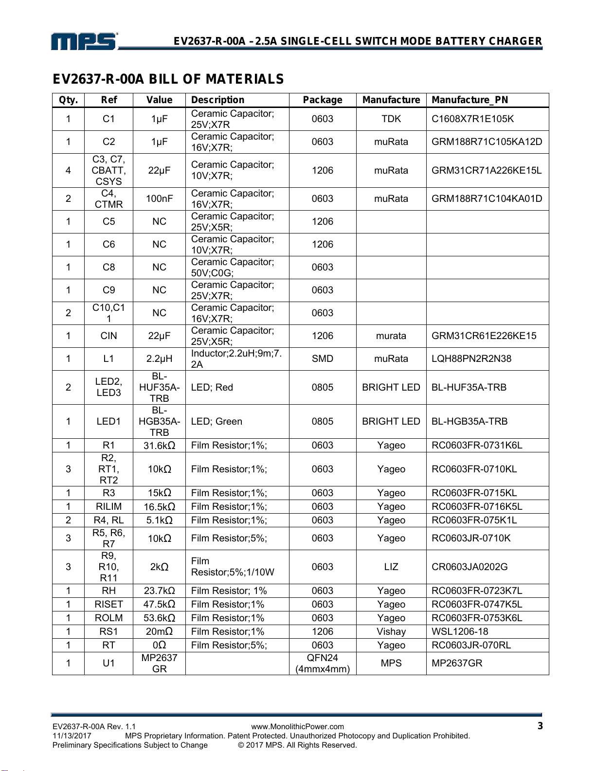
EV2637-R-00A BILL OF MATERIALS
Qty. Ref Value Description Package Manufacture Manufacture_PN
1 C1 1F Ceramic Capacitor;
25V;X7R 0603 TDK C1608X7R1E105K
1 C2 1F Ceramic Capacitor;
16V;X7R; 0603 muRata GRM188R71C105KA12D
4
C3, C7,
CBATT,
CSYS
22F Ceramic Capacitor;
10V;X7R; 1206 muRata GRM31CR71A226KE15L
2 C4,
CTMR 100nF Ceramic Capacitor;
16V;X7R; 0603 muRata GRM188R71C104KA01D
1 C5 NC
Ceramic Capacitor;
25V;X5R; 1206
1 C6 NC
Ceramic Capacitor;
10V;X7R; 1206
1 C8 NC
Ceramic Capacitor;
50V;C0G; 0603
1 C9 NC
Ceramic Capacitor;
25V;X7R; 0603
2 C10,C1
1 NC Ceramic Capacitor;
16V;X7R; 0603
1 CIN 22F Ceramic Capacitor;
25V;X5R; 1206 murata GRM31CR61E226KE15
1 L1 2.2H Inductor;2.2uH;9m;7.
2A SMD muRata LQH88PN2R2N38
2 LED2,
LED3
BL-
HUF35A-
TRB
LED; Red 0805 BRIGHT LED BL-HUF35A-TRB
1 LED1
BL-
HGB35A-
TRB
LED; Green 0805 BRIGHT LED BL-HGB35A-TRB
1 R1
31.6kFilm Resistor;1%; 0603 Yageo RC0603FR-0731K6L
3
R2,
RT1,
RT2
10kFilm Resistor;1%; 0603 Yageo RC0603FR-0710KL
1 R3 15kFilm Resistor;1%; 0603 Yageo RC0603FR-0715KL
1 RILIM
16.5kFilm Resistor;1%; 0603 Yageo RC0603FR-0716K5L
2 R4, RL 5.1kFilm Resistor;1%; 0603 Yageo RC0603FR-075K1L
3 R5, R6,
R7 10kFilm Resistor;5%; 0603 Yageo RC0603JR-0710K
3
R9,
R10,
R11
2kFilm
Resistor;5%;1/10W 0603 LIZ CR0603JA0202G
1 RH 23.7kFilm Resistor; 1% 0603 Yageo RC0603FR-0723K7L
1 RISET
47.5kFilm Resistor;1% 0603 Yageo RC0603FR-0747K5L
1 ROLM
53.6kFilm Resistor;1% 0603 Yageo RC0603FR-0753K6L
1 RS1 20mFilm Resistor;1% 1206 Vishay WSL1206-18
1 RT 0Film Resistor;5%; 0603 Yageo RC0603JR-070RL
1 U1
MP2637
GR QFN24
(4mmx4mm) MPS MP2637GR

EV2637-R-00A –2.5A SINGLE-CELL SWITCH MODE BATTERY CHARGER
EV2637-R-00A Rev. 1.1 www.MonolithicPower.com 4
11/13/2017 MPS Proprietary Information. Patent Protected. Unauthorized Photocopy and Duplication Prohibited.
Preliminary Specifications Subject to Change © 2017 MPS. All Rights Reserved.
PRINTED CIRCUIT BOARD LAYOUT
Figure 1: Top Silkscreen Layer Figure 2: Top Layer
Figure 3: Bottom Layer
EV2637-R-00A –2.5A SINGLE-CELL SWITCH MODE BATTERY CHARGER
EV2637-R-00A Rev. 1.1 www.MonolithicPower.com 5
11/13/2017 MPS Proprietary Information. Patent Protected. Unauthorized Photocopy and Duplication Prohibited.
Preliminary Specifications Subject to Change © 2017 MPS. All Rights Reserved.
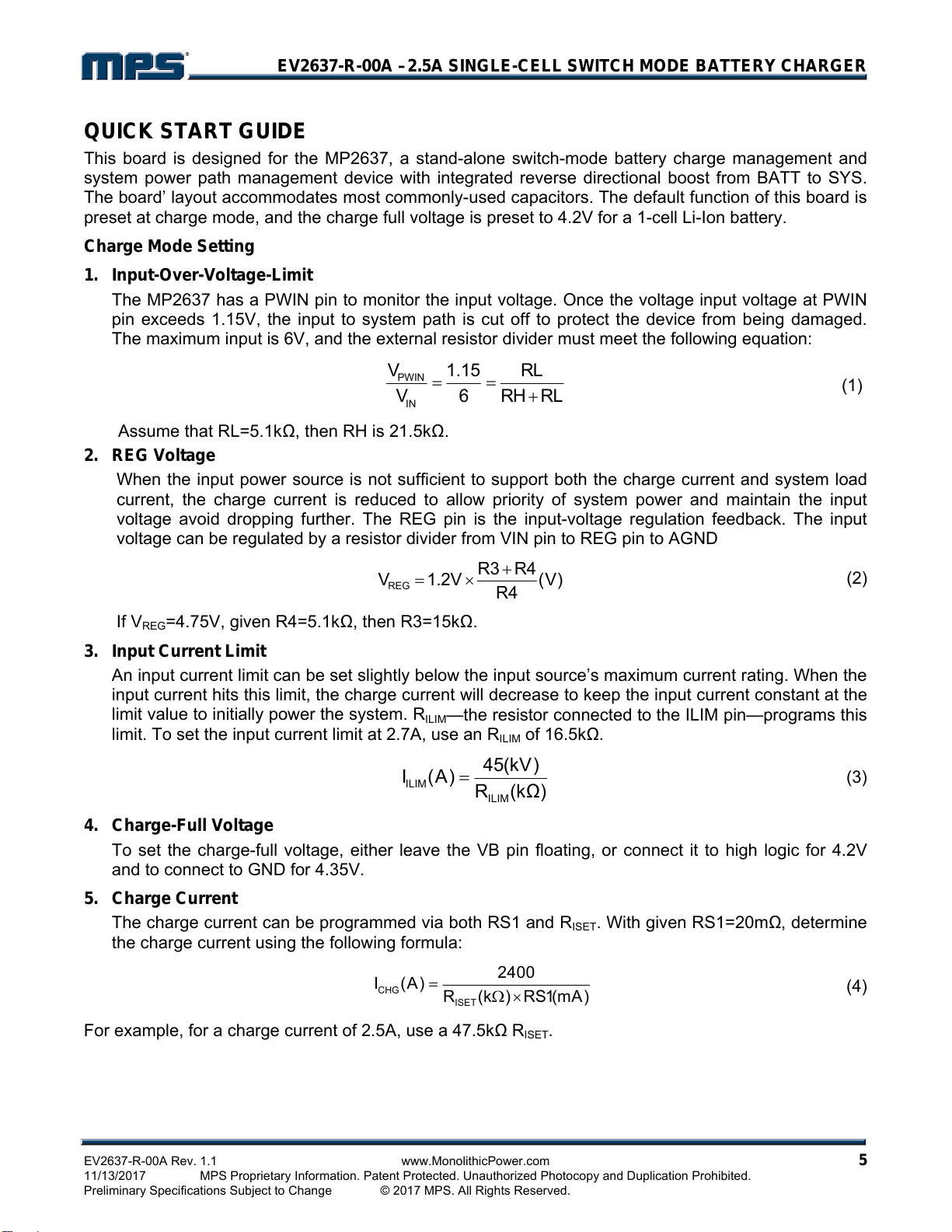
QUICK START GUIDE
This board is designed for the MP2637, a stand-alone switch-mode battery charge management and
system power path management device with integrated reverse directional boost from BATT to SYS.
The board’ layout accommodates most commonly-used capacitors. The default function of this board is
preset at charge mode, and the charge full voltage is preset to 4.2V for a 1-cell Li-Ion battery.
Charge Mode Setting
1. Input-Over-Voltage-Limit
The MP2637 has a PWIN pin to monitor the input voltage. Once the voltage input voltage at PWIN
pin exceeds 1.15V, the input to system path is cut off to protect the device from being damaged.
The maximum input is 6V, and the external resistor divider must meet the following equation:
PWIN
IN
V1.15 RL
V6RHRL
(1)
Assume that RL=5.1k, then RH is 21.5k.
2. REG Voltage
When the input power source is not sufficient to support both the charge current and system load
current, the charge current is reduced to allow priority of system power and maintain the input
voltage avoid dropping further. The REG pin is the input-voltage regulation feedback. The input
voltage can be regulated by a resistor divider from VIN pin to REG pin to AGND
)V(
4R
4RR3
V2.1VREG
(2)
If VREG=4.75V, given R4=5.1k, then R3=15k.
3. Input Current Limit
An input current limit can be set slightly below the input source’s maximum current rating. When the
input current hits this limit, the charge current will decrease to keep the input current constant at the
limit value to initially power the system. RILIM—the resistor connected to the ILIM pin—programs this
limit. To set the input current limit at 2.7A, use an RILIM of 16.5k.
ILIM
ILIM
45(kV)
I(A)R(k)(3)
4. Charge-Full Voltage
To set the charge-full voltage, either leave the VB pin floating, or connect it to high logic for 4.2V
and to connect to GND for 4.35V.
5. Charge Current
The charge current can be programmed via both RS1 and RISET. With given RS1=20m, determine
the charge current using the following formula:
CHG
ISET
2400
I(A)
R(k)RS1(mA)
(4)
For example, for a charge current of 2.5A, use a 47.5kRISET.
EV2637-R-00A –2.5A SINGLE-CELL SWITCH MODE BATTERY CHARGER
EV2637-R-00A Rev. 1.1 www.MonolithicPower.com 6
11/13/2017 MPS Proprietary Information. Patent Protected. Unauthorized Photocopy and Duplication Prohibited.
Preliminary Specifications Subject to Change © 2017 MPS. All Rights Reserved.
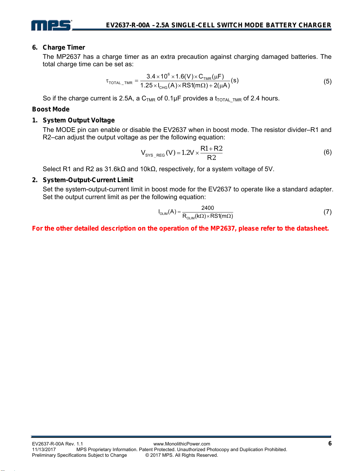
6. Charge Timer
The MP2637 has a charge timer as an extra precaution against charging damaged batteries. The
total charge time can be set as:
6
TMR
TOTAL _ TMR
CHG
3.4 10 1.6(V) C ( F) (s)
1.25 I (A) RS1(m ) 2( A)
(5)
So if the charge current is 2.5A, a CTMR of 0.1F provides a tTOTAL_TMR of 2.4 hours.
Boost Mode
1. System Output Voltage
The MODE pin can enable or disable the EV2637 when in boost mode. The resistor divider–R1 and
R2–can adjust the output voltage as per the following equation:
221
2.1)(
_R
RR
VVV REGSYS
(6)
Select R1 and R2 as 31.6kand 10k, respectively, for a system voltage of 5V.
2. System-Output-Current Limit
Set the system-output-current limit in boost mode for the EV2637 to operate like a standard adapter.
Set the output current limit as per the following equation:
OLIM
OLIM
2400
I(A)
R(k)RS1(m)
(7)
For the other detailed description on the operation of the MP2637, please refer to the datasheet.

EV2637-R-00A –2.5A SINGLE-CELL SWITCH MODE BATTERY CHARGER
EV2637-R-00A Rev. 1.1 www.MonolithicPower.com 7
11/13/2017 MPS Proprietary Information. Patent Protected. Unauthorized Photocopy and Duplication Prohibited.
Preliminary Specifications Subject to Change © 2017 MPS. All Rights Reserved.
EQUIPMENT REQUIREMENT
Evaluation requires the following equipments:
1. DC power source. The output voltage should exceed 6.0V, and output current greater than 2.5A.
2. Battery simulator or a single-cell battery pack. The battery simulator’s output rating should
exceed 4.5V/3.0A. When using a real battery pack, please observe all precautions on the
battery manufacturer’s data sheet first and ensure the charger’s setting doesn’t exceed the
battery’s absolute maximum specifications.
3. An oscilloscope. A single voltage probe and a single current probe.
4. Multi-meter.
Charge Function
1 Connect the jumper “EN” to “H” and the “MODE” to “L” to shunts, respectively!
2 Attach the positive and negative ends of the battery to the “BATT” and “GND” terminals,
respectively. If it’s a battery simulator, please preset the voltage to 3.8V (typical value) first.
3 Preset the DC power source to 5.0V. Then attach the DC output port and ground to the “VIN”
and “GND” terminals, respectively.
4 Turn on the DC power source. The charger will start. Use the oscilloscope to verify that the 2.5A
charge current is being delivered to the battery.
5 Remove the shunt between the “EN” and “H” to disable charging.
6 Re-insert the shunt between the “EN” and “H” to enable charging.
Figure 4: Setup for Charge Mode
EV2637-R-00A –2.5A SINGLE-CELL SWITCH MODE BATTERY CHARGER
NOTICE: The information in this document is subject to change without notice. Users should warrant and guarantee that third
party Intellectual Property rights are not infringed upon when integrating MPS products into any application. MPS will not
assume any legal responsibility for any said applications.
EV2637-R-00A Rev. 1.1 www.MonolithicPower.com 8
11/13/2017 MPS Proprietary Information. Patent Protected. Unauthorized Photocopy and Duplication Prohibited.
Preliminary Specifications Subject to Change © 2017 MPS. All Rights Reserved.
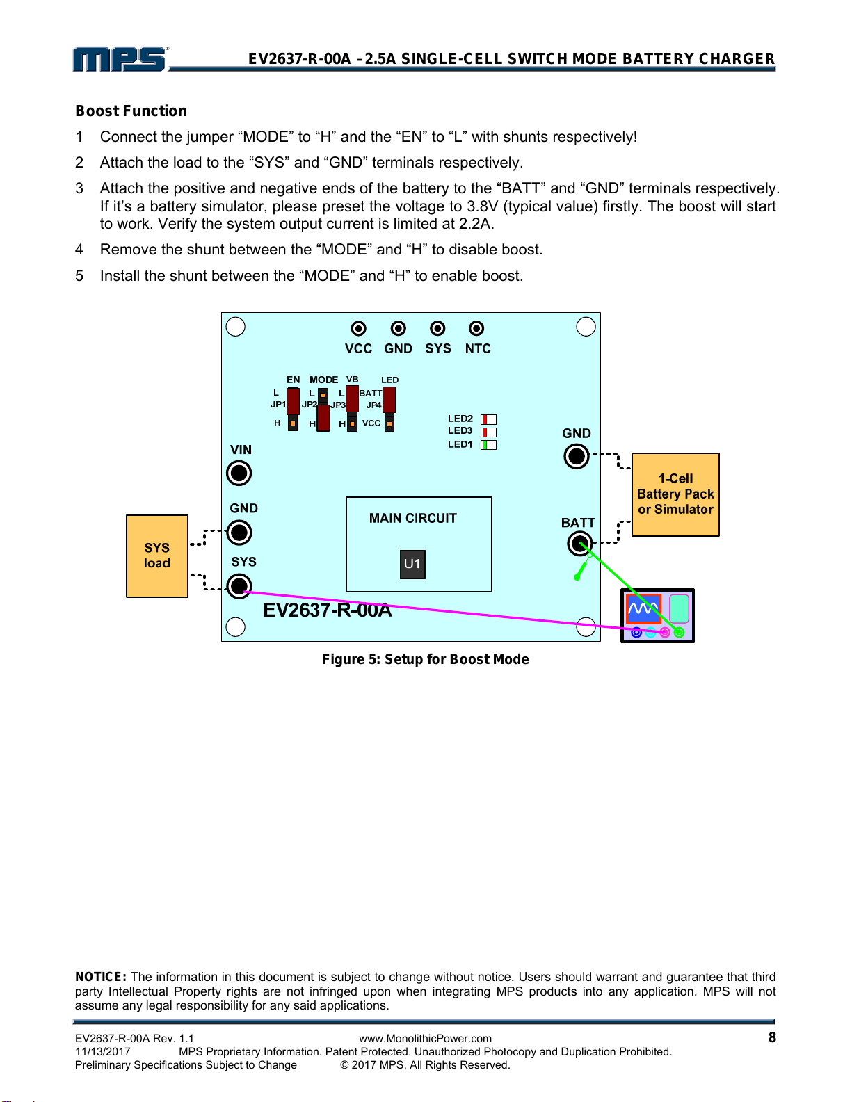
Boost Function
1 Connect the jumper “MODE” to “H” and the “EN” to “L” with shunts respectively!
2 Attach the load to the “SYS” and “GND” terminals respectively.
3 Attach the positive and negative ends of the battery to the “BATT” and “GND” terminals respectively.
If it’s a battery simulator, please preset the voltage to 3.8V (typical value) firstly. The boost will start
to work. Verify the system output current is limited at 2.2A.
4 Remove the shunt between the “MODE” and “H” to disable boost.
5 Install the shunt between the “MODE” and “H” to enable boost.
Figure 5: Setup for Boost Mode
Table of contents
Other MPS Batteries Charger manuals


