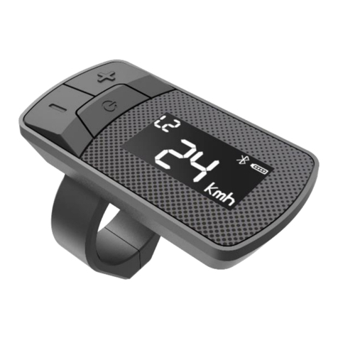
MPS EDS-E1 User manual

EDS-E1
User’s Manual
Website: https://www.mpsenergy.com.tw/
Visit us:

Content
1. Specification ...................................................................................................................... 3
2. Operation .......................................................................................................................... 4
2.1. How to power on HMI................................................................................................... 4
2.2. How to power off .......................................................................................................... 4
2.3. LED Lights information .................................................................................................. 4
2.3.1. Battery Indication...................................................................................................... 5
2.3.2. Assist levels............................................................................................................... 6
2.3.3. Walk mode................................................................................................................ 6
2.3.4. Headlight ON/OFF..................................................................................................... 7
2.3.5. Bike status monitoring .............................................................................................. 7
2.3.6. Controller status monitoring..................................................................................... 8
2.4. Connection problem.................................................................................................... 10
2.5. BLE connection............................................................................................................ 10
2.6. Update Mode .............................................................................................................. 11

1. Specification
Input Voltage
24 ~ 60 V
Communication
Interface
UART for controller
BLE for app
Display
LED
Key
Power / + / - button
Operating
Temperature
-20°C ~ 60°C
IP
IP65
Certifications
ISO 13849-1 2015 certification
Up key
Down key
Power key
Battery Indicator
BLE Indicator
Level Indicator

2. Operation
2.1.How to power on HMI
Long press “Power key” for 3 seconds to power on the HMI. After powering up the
HMI, you will see all indicator lights turned on as the following figure.
2.2.How to power off
During HMI at power on state, you can long press “power key” for 3 seconds to
power off the HMI.
2.3.LED Lights information
You can check the current status using the LED lights information. There are 7 LED
lights on the HMI, their positions are labeled with number ① ~ ⑦ as the following
figure.
⑦
①
②
③
④
⑤
⑥

2.3.1. Battery Indication
You can check the battery level to know the current battery capacity as the following
figure. LED ④, ⑤and ⑥represent battery levels in normal mode.
-
Battery 76% ~100%
Battery 51% ~ 75%
Battery 26% ~ 50%
Battery 0% ~ 25%
(LED ④ blink)
Battery Unknown
(LED ④, ⑤and ⑥blink)

2.3.2. Assist levels
Short press UP / DOWN key to switch the assist level. Top level is 3, 0 for neutral. LED
①, ②, and ③ represent assist levels in normal mode.
2.3.3. Walk mode
Keep pressing the DOWN key to enter the Walk mode. The speed limit for Walk
mode is 6km/h.
Release the DOWN key to return back to the assist mode.
Walk mode
(LED ①, ②, and ③ blink )
Level 0
Level 1
Level 2
Level 3

2.3.4. Headlight ON/OFF
Long press the UP key for 1 second. Once the headlight icon is displayed on the
screen, the headlight is ON. To turn OFF, press the UP key for 1 second.
2.3.5. Bike status monitoring
The blinking LED ①, ②, and ③ represent different bike status, it can assist user to
check the status of the E-bike.
For status like:
Speed is over Speed Limit
Brake status
Temperature is above the limited value on the controller
If any of these status happens, the controller shall stop the motor output
immediately.
Speed is over Speed Limit
(LED ① blink,
LED ④, ⑤and ⑥ remain as battery level)
Brake (LED ②blink,
LED ④, ⑤and ⑥ remain as battery level)

2.3.6. Controller status monitoring
The combination of blinking LEDs (①~ ⑥) represent different controller status.
These status can assist user to check the state of the controller.
If any of below status happens:
OC (Over Current)
OT (Over Temperature)
OV (Over Voltage)
UV (Under Voltage)
Software Error
The controller shall stop the motor output immediately.
Temperature is above the limited value on the controller
(LED ③blink, LED ④, ⑤and ⑥ remain as battery level)
OV (Over Voltage)
(LED ①and ②blink)
OT (Over Temperature)
(LED ②and ③blink)

OC (Over Voltage)
(LED ①and ③blink)
UV (Under Voltage)
(LED ④and ⑥blink)
Software Error
(LED ⑤and ⑥blink)

2.4.Connection problem
If there is any connection problem between the controller and the HMI, a timeout
status will be showed by LED ①, ②, ④and ⑤will blink.
Please try to switch the HMI and battery off first, and check if the cables are well
connected and then switch on HMI again. If the problem persists, please contact the
manufacturer for assistance.
2.5.BLE connection
When the APP establishes a BLE connection with the HMI, on HMI it shall start the
BLE pin code mode, LED ⑦ will start blinking. LED ①~ ⑥will remain the same as
normal mode.
※In this state, user can long press the UP and DOWN keys simultaneously for 2
seconds to reset the BLE pin code to the default code (0000).
Timeout
(LED ①, ②, ④and ⑤blink)
Pin code mode
(LED ⑦blink)

After user input the BLE pin code on the APP and the pin code is correct, the HMI
shall return to normal mode. LED ⑦will continue turned on to indicate that the BLE
connection is established. Please check the following two examples:
2.6.Update Mode
When power user updating the parameter or firmware version of the controller, the
display will enter the update mode. LED ②, ⑤and ⑦will remain on until the
update is completed. Normal user will not see this mode.
Update mode
(LED ②, ⑤, and ⑦)
BLE Connected
BLE Connected, Assist Level 3, Battery > 75%
Table of contents
Other MPS Measuring Instrument manuals
Popular Measuring Instrument manuals by other brands
Hanna Instruments
Hanna Instruments HI6421 instruction manual
Agilent Technologies
Agilent Technologies U1401B User's guide and service guide
Midtronics
Midtronics CPX-950 EU user manual
Titanium
Titanium TRL-10R Kit instruction manual
Chauvin Arnoux
Chauvin Arnoux AEMC Digital FlexProbe 400D-6 user manual

FLIR
FLIR CM275 user manual
