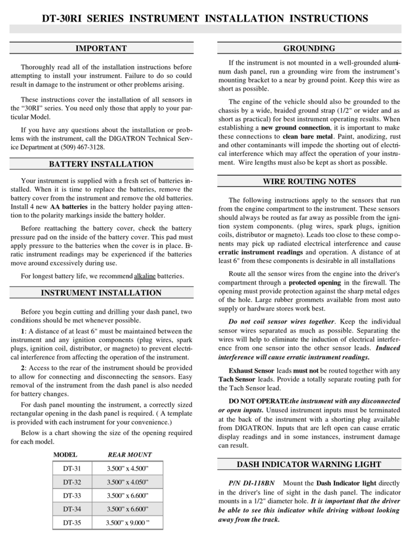
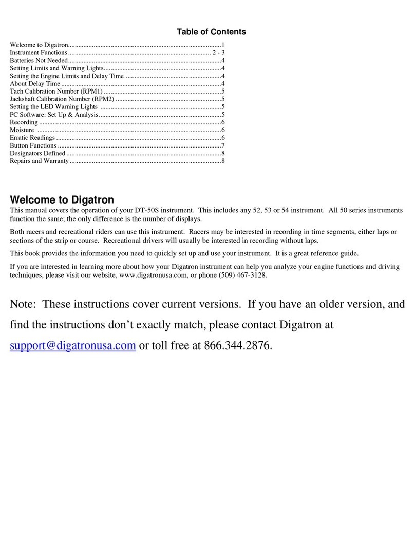
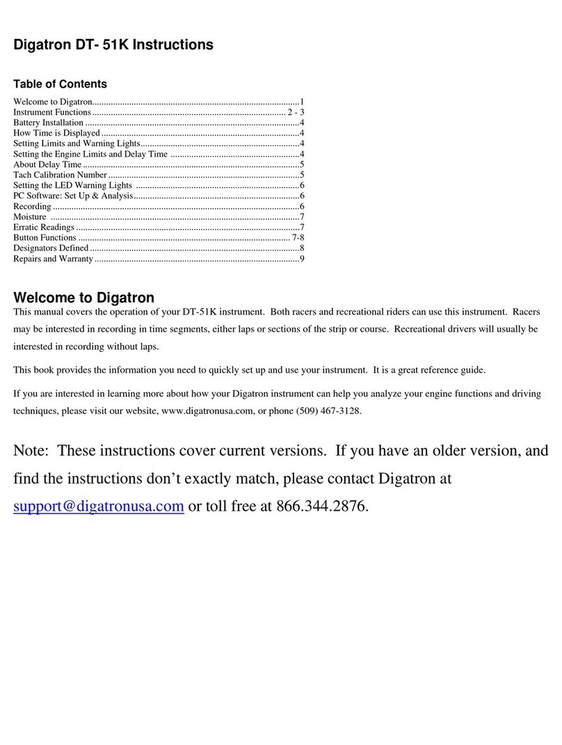
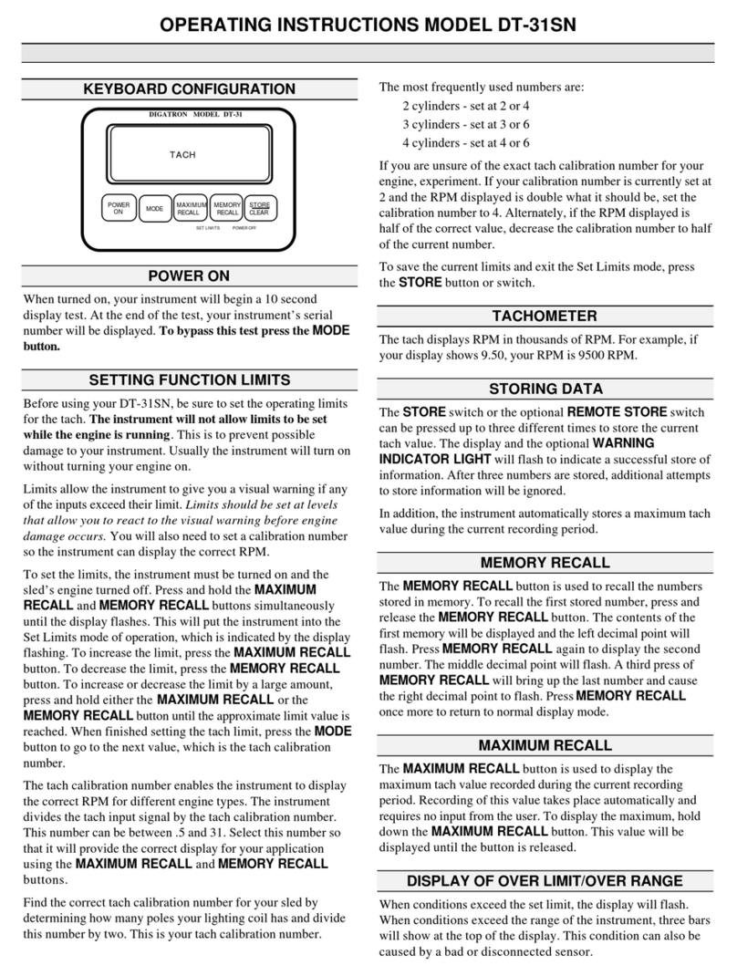
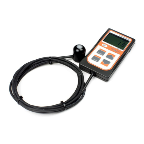
Digatron DT-46KL User manual

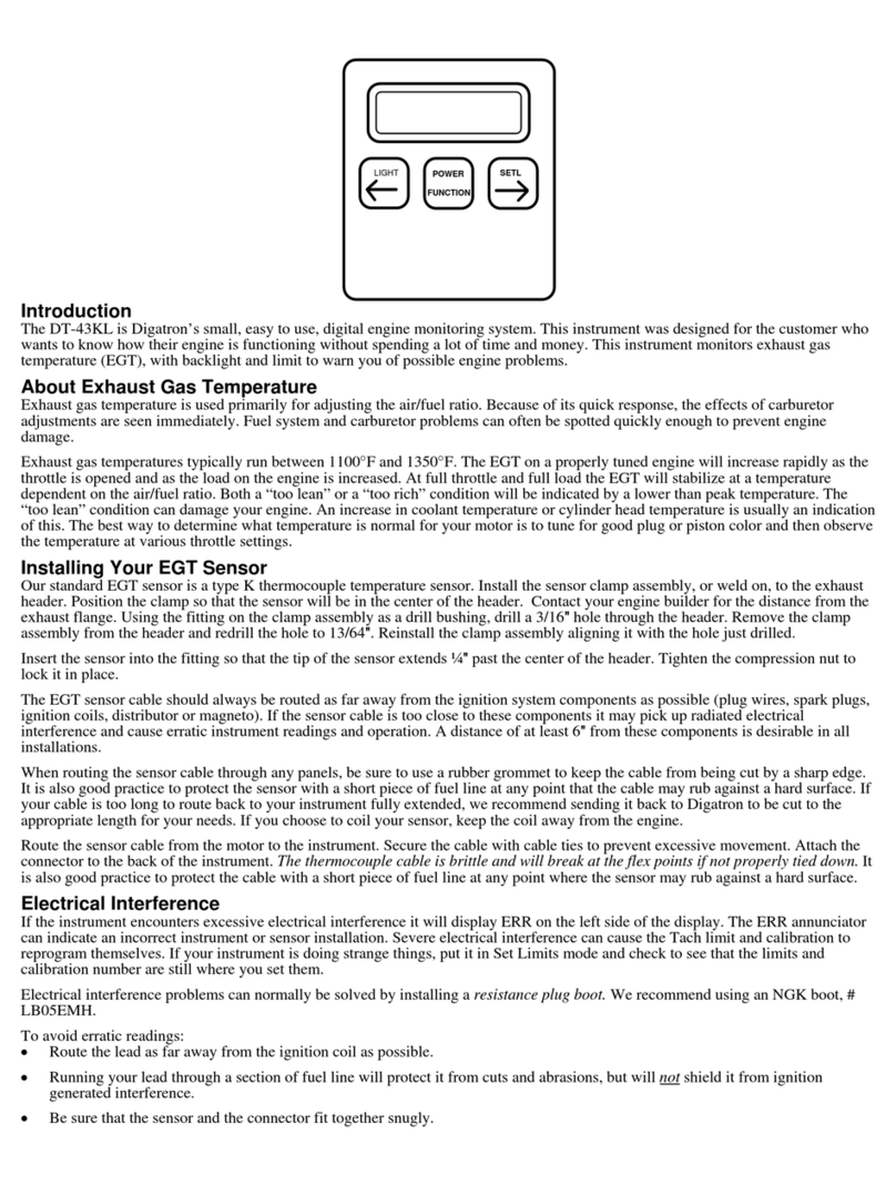
LIGHT
FUNCTION
POWER SETL
Introduction
The DT-46KL is Digatron’s small, easy to use, digital engine monitoring system. This instrument
was designed for the customer who wants to know how their engine is functioning without
spending a lot of time and money. This instrument monitors tachometer (Tach) and cylinder head
temperature (CHT) with backlight and limits to warn you of possible engine problems.
The Two Modes of the DT-46KL
This instrument has two basic modes of operation, Set Limits and Monitor.
A. Set Limits mode is necessary before using your unit for the first time and if you use it on
different engines. Limits help you prevent possible engine damage.
B. Monitor mode is used while operating your kart to watch your engine RPM for irregular
activity.
A. Setting the Function Limits On Your DT-46KL
Before using your DT-46KL, be sure to set the operating limits for each input. Limits allow the
instrument to give you a visual warning (the display flashes) if any of the inputs exceed their
limit. Limits should be set at levels that allow you to react to the visual warning before engine
damage occurs
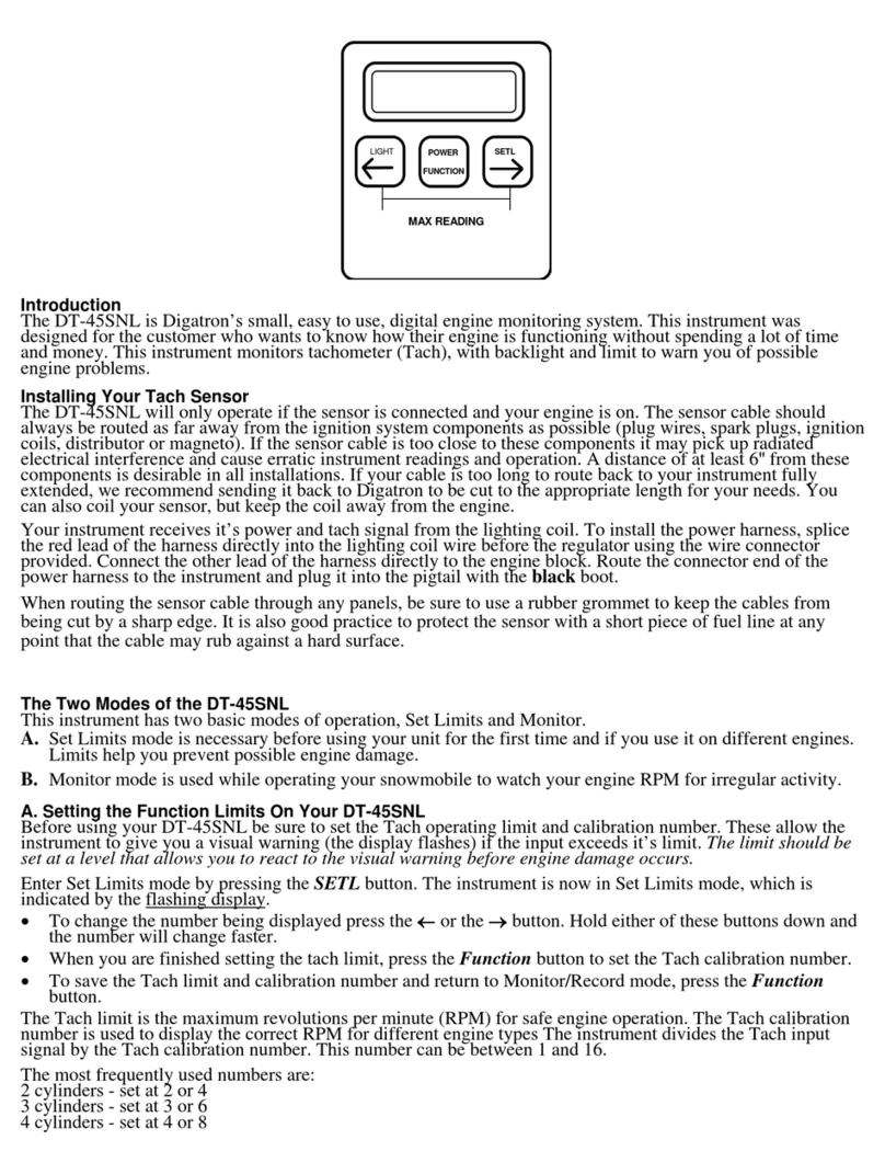
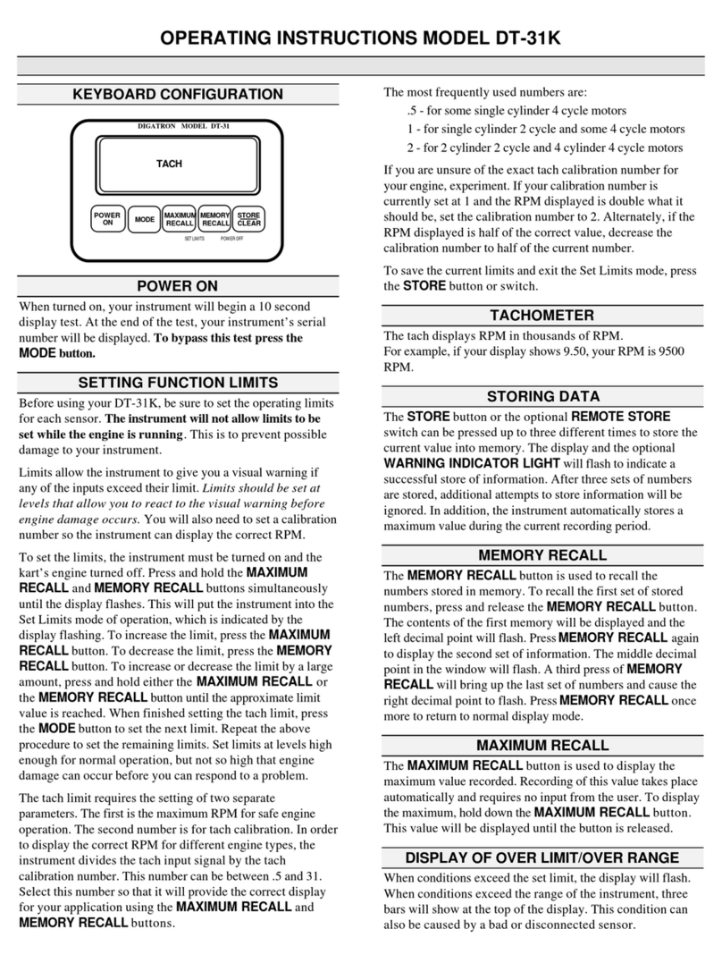
•Enter Set Limits mode by pressing the SETL button. The instrument is now in Set Limits
mode, which is indicated by the flashing display.
•To change the number being displayed press the ←or the →button. Hold either of these
buttons down and the number will change faster.
•When you are finished setting the first limit, press the Function button to set the next limit.
•Repeat the above procedure to set the remaining limit and the Tach calibration number.
•To save the current limits and return to Monitor/Record mode, press the Function button.
Note: Set limits at levels high enough for normal operation, but not so high that engine damage
can occur before you can respond to a problem.
Limits are set in the following order: CHT, Tach and the Tach calibration number. Tach requires
two separate parameters. The first is the maximum revolutions per minute (RPM) for safe engine
operation. The second number is for Tach calibration. In order to display the correct RPM for
different engine types, the instrument divides the Tach input signal by the Tach calibration
number. This number can be between .5 and 31.
The most frequently used numbers are:
.5 - for some single cylinder 4 cycle motors
1 - for single cylinder 2 cycle and some 4 cycle motors
2 - for 2 cylinder 2 cycle and 4 cylinder 4 cycle motors

If you are unsure of the Tach calibration number for your engine, experiment. If your calibration
number is currently set at 1 and the RPM displayed is double what it should be, set the calibration
number to 2. Alternately, if the RPM displayed is half of the correct value, decrease the
calibration number to half the current number.
B. Monitor Mode is Used While on the Track
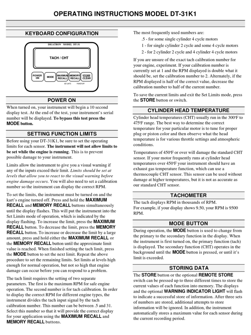
When your instrument is powered on, it is in Monitor mode. This is the mode the unit will be in
so you can observe your engine functions. During Monitor mode you can make quick tuning
adjustments to your powertrain that allow you to run safe and fast. The instrument will visually
warn you, by flashing the display, if your engine exceeds it’s set limit. This limit allows you to
avoid engine damage.
•To view your maximum readings since the engine was turned on, press the ←and the →
buttons at the same time.
•The backlight is used to illuminate your display for use at night. Press the LIGHT button to
toggle the backlight on or off. The backlight can only be turned on or off while in Monitor
mode.
The DT-46KL Uses One AAA Batteries (not included)
The DT-46KL can run, without a backlight, for 200 hours on one AAA battery. When using the
backlight, one battery will power the instrument for 50 hours.
With the front of the instrument facing you, remove the left end cap. Remove the battery from the
holder. Observe polarity when replacing the battery. Replace the end cap.
Installing Your Sensors
Do not operate your DT-46KL unless both sensors are connected. Inputs that are left open can
cause erratic readings and possible instrument damage. If you do not want to use the
instrument’s CHT function, the pigtail on the back of the instrument must be terminated with a
shorting plug available from Digatron. The Tach function must be used to operate the instrument.
Sensor cables that run from the engine compartment to the instrument should always be routed as
far away from the ignition system components as possible (plug wires, spark plugs, ignition coils,
distributor or magneto). Sensor cables too close to these components may pick up radiated
electrical interference and cause erratic instrument readings and operation. A distance of at least
6"from these components is desirable in all installations.
When routing sensor cables through any panels, be sure to use a rubber grommet to keep the
cables from being cut by a sharp edge. It is also good practice to protect all of the sensors with a
short piece of fuel line at any point that the cable may rub against a hard surface.
If either of your cables are too long to route back to your instrument fully extended, we
recommend sending your sensors back to Digatron to be cut to the appropriate length for your
needs or coiling them each separately. If you do coil your sensors, keep the coils away from the
engine.
Tach Sensor Installation
Our standard Tach sensor can be installed on both two and four cycle engines. Use a cable tie on
the shrink tube, at the end of the green wire, to attach the sensor to the plug wire, keeping the end
at least 2"from the plug boot. Keep the sensor electronics (red) away from any ignition
component. If you experience erratically low Tach readings, attach the green wire, inch by inch,
to the plug wire until you have correct readings. Attach the end of the black ground wire to the
bare metal on the engine block. Route the sensor cable from the motor to the rear of your
instrument and secure with cable ties. Plug into the pigtail with the “push-on” type connector.
How the Tachometer Reading is Displayed
The Tach displays RPM in thousands of RPM. For example, if your display shows 9.50, your
RPM is 9500.

CHT Sensor Installation
Our standard CHT sensor is for air cooled engines only. For temperatures consistently above
450ºF we have a thermocouple sensor.
Remove the spark plug from the cylinder you wish to monitor and discard the plug washer. Check
the surface of the head around the spark plug hole for a smooth, flat finish to assure a good seal
when the sensor is installed.
Position the sensor over the spark plug hole and check that you have sufficient clearance around
the outside of the sensor body to avoid damage when the plug is installed and tightened. This may
require some minor machining on some installations. Install the spark plug finger tight to hold the
sensor in position. Finish tightening with a plug wrench to the same torque as normally
recommended. Do not allow the sensor to turn as you tighten the plug. The sensor is easily
damaged if forced into a cooling fin.
Route the sensor cable from the motor to the instrument. Secure the cable to the frame of the kart
with cable ties. Connect to the small, threaded pigtail on the instrument and turn the connector
until tight.
About Cylinder Head Temperature
Cylinder head temperatures (CHT) usually run in the 300ºF to 475ºF range. The best way to
determine the correct temperature for your particular motor is to tune for proper plug or piston
color and then observe what the head temperature is for various throttle settings and atmospheric
conditions.
Temperatures consistently over 450ºF will damage the standard CHT sensor. If your motor
frequently runs at cylinder head temperatures over 450ºF your instrument should have an exhaust
gas temperature function, which can use a thermocouple CHT sensor. This sensor can be used
without damage at higher temperatures, but it is not as accurate as our standard CHT sensor.
Water Temperature Sensor Installation
The water temperature sensor attaches to the standard CHT pigtail. Water temperature should be
taken from a point well below the water level in the block, or from a fitting provided for this
purpose in the head (do not use the radiator).
The sensor can also be placed inline in the hose where coolant exits the engine. This is not
recommended, but if this is the only location available, be sure the inline pipe is grounded to the
engine block.
The compression fitting provided with the sensor is an 1/8″NPT. You may need to use a reducing
bushing in some applications to adapt the compression fitting to an available water temperature
port. When installing the sensor, be sure that at least 1″of the probe is in the water.
Route the sensor cable from the motor to the instrument. Secure the cable to the frame of the kart
with cable ties. Connect to the small, threaded pigtail on the instrument and turn the connector
until tight.
About Water Temperature
Set the water temperature limit so the coolant in your engine does not exceed it’s boiling point.
Steering Wheel Mount
Attach the three slotted holes on the large side of the mount to the bolts on the center of your
steering wheel. Place the nuts on the back of the instrument through the two holes on the other
side of the mount. Slide the instrument firmly to the side to lock it in place. Adjust the nuts on the
instrument for a tight fit.
Electrical Interference
If the instrument encounters excessive electrical interference it will display ERR on the left side
of the display. The ERR annunciator can indicate an incorrect instrument or sensor installation.
Severe electrical interference can cause the Tach limit and calibration to reprogram themselves. If
your instrument is doing strange things, put it in Set Limits mode and check to see that the limits

and calibration number are still where you set them. Electrical interference problems can
normally be solved by installing a resistance plug boot. We recommend using an NGK boot, #
LB05EMH.
To avoid erratic readings:
•Route the lead as far away from the ignition coil as possible.
•Running your lead through a section of fuel line will protect it from cuts and abrasions, but
will not shield it from ignition generated interference.
Be sure that the sensor and the connector fit together snugly.
Troubleshooting
The following are explanations to some commonly asked questions.
What are those letters on the side of my display?
There are two annunciators that may be displayed on the left side of your display.
CHT stands for Cylinder Head Temperature
RPM stands for Revolutions per Minute, also called Tach.
ERR stands for Error and could mean that your instrument has encountered extreme electrical
interference. This can possibly cause the instrument to reprogram it’s limit and calibration
number.
Why is the Display Flashing?
This signifies that you are either in Set Limits mode or that your engine exceeded it’s limit.
Repairs
If you have any questions about the operation of your instrument, please call. One of our
technicians will be happy to help you. Please have your instrument nearby to help while
troubleshooting with the technician.
Your instrument is warranted to be free from factory defects and electronic failure for one year
from the date of purchase. Physical damage during normal usage is not covered under the
warranty. Be sure to fill out and return your warranty card for our records. If we do not have a
card on file for your instrument, you will be charged for repairs unless you can provide us with
proof of purchase date.
When returning an instrument for repair, please use the repair form found on our website or
enclose a note indicating your return address, phone number and a detailed description of the
problem. Send your instrument and sensors so that we can check the complete system.
Send repairs to:
Digatron
120 N. Wall St. Ste. 300
Spokane, WA 99201
www.digatronusa.com
Phone: (509) 467-3128 Fax: (509) 467-2952 5/7/2008
Table of contents
Other Digatron Measuring Instrument manuals

Digatron
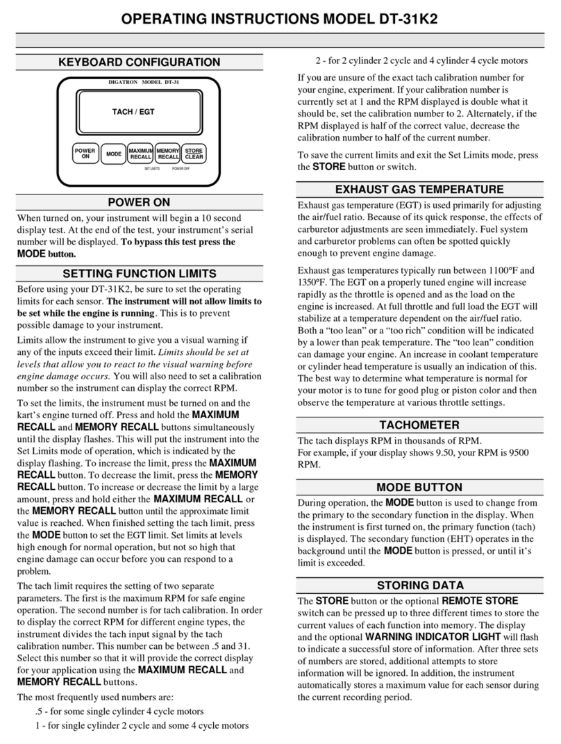
Digatron DT-31K2 User manual

Digatron
Digatron DT-31K User manual

Digatron
Digatron DT-31SN User manual

Digatron
Digatron DT-31SN2 User manual

Digatron
Digatron DT-40K User manual

Digatron
Digatron DT- 31K LT User manual

Digatron
Digatron DT-43KL User manual

Digatron
Digatron DT-45SNL User manual

Digatron
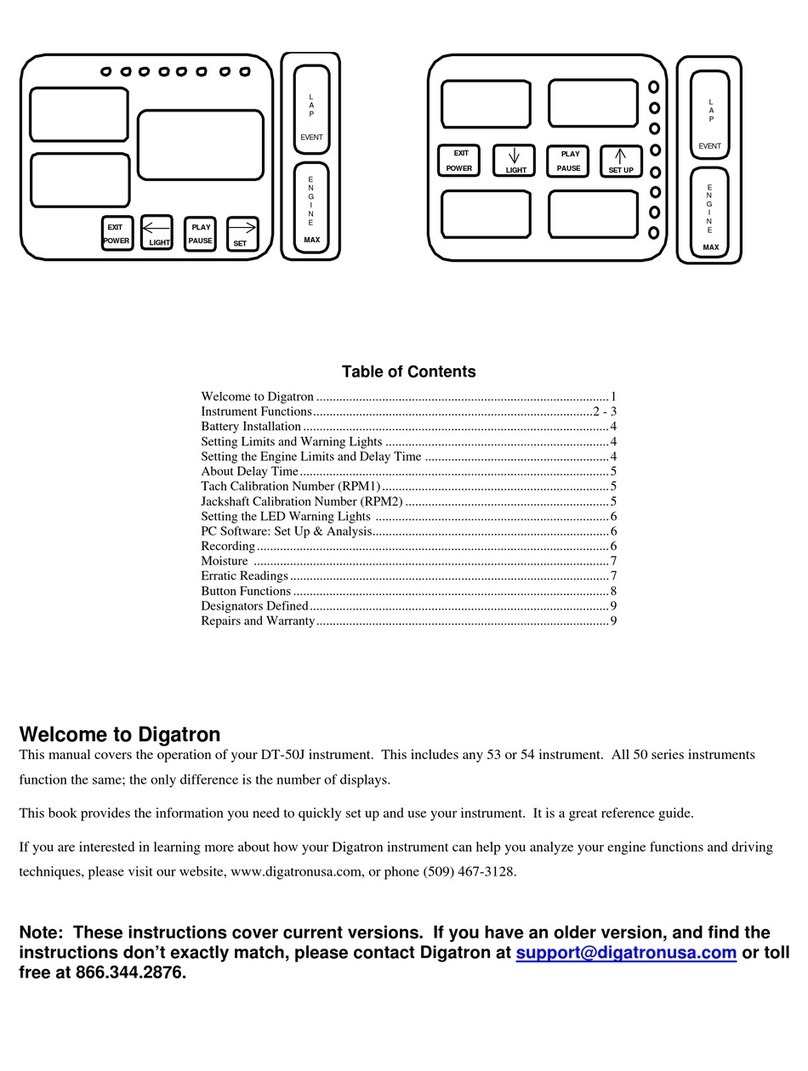
Digatron DT-50S User manual

Digatron
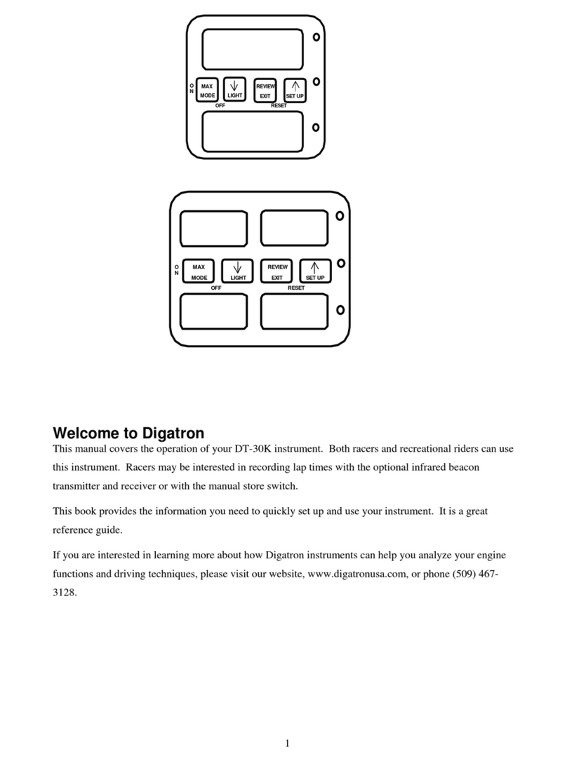
Digatron DT-30K User manual