SONIX 10D Installation instructions

ULTRASONIC FLOWMETER
SONIX 10D
INSTRUCTION FOR ASSEMBLY AND OPERATING
SONIX®
Industri l Electronic Devices
ul. Leopold Lis -Kuli 12, 05-270 M rki, Pol nd
phone:+4822-7811133, f x: +4822-7811644
www.sonix.com.pl

Instructions for Assembly nd Oper ting SONIX 10D
Contents
GENERAL INFORMATIONS ON SAFETY................................................................................................. 3
Introduction............................................................................................................................................ 3
Symbols................................................................................................................................................. 3
Discl imer.............................................................................................................................................. 3
INTRODUCTION........................................................................................................................................ 4
Component p rts .................................................................................................................................. 4
List of supplied elements....................................................................................................................... 5
Purpose ................................................................................................................................................ 5
B sic technic l d t .............................................................................................................................. 5
ASSEMBLY........................................................................................................................................... 6
Mech nic l ssembly of the flow sensor ...............................................................................................6
Me surement ex mple of sew ge flow in gr vit tion l pipeline ....................................................6
Length of str ight sections of the pipeline.........................................................................................6
Recommend tions for the flow sensor ssembly..............................................................................7
The producer’s supervision over the ssembly nd st rt-up .................................................................7
Sp ce for the ssembly of ultr sound probes ..................................................................................7
User’s prep r tion for ssembly ...................................................................................................... 8
Assembly of the me suring tr nsducer.................................................................................................. 8
Electric l connections ...................................................................................................................... 9
Probe's c ble correct ending.......................................................................................................... 10
Gener l Inform tion ............................................................................................................................ 10
Descriptions of the menu..................................................................................................................... 10
E0 Flow Volume.............................................................................................................................. 11
E1 Upper threshold Lower threshold...............................................................................................11
E2 Di gnostic screen...................................................................................................................... 11
E3 Working time Time of correct work............................................................................................11
E4 SONIX...................................................................................................................................... 11
User’s functions................................................................................................................................... 11
Neg tive volume............................................................................................................................. 11
P ssword ch nge........................................................................................................................... 12
St rting the b cklight...................................................................................................................... 12
Ch nge of current nd r nge.......................................................................................................... 12
Setting the thresholds..................................................................................................................... 12
Ch nge of displ y precision ........................................................................................................... 12
Ch nge of the const nt of time, c libr tion of the current output ...................................................12
P r meters of the RS485 output.................................................................................................... 12
Exiting user’s functions................................................................................................................... 12
Tempor ry volume.......................................................................................................................... 12
Servicing ............................................................................................................................................. 12
ERRORS.................................................................................................................................................. 13
Gener l inform tion............................................................................................................................. 13
Di gnostic mess ges........................................................................................................................... 13
THE SERIES RS485 OUTPUT................................................................................................................. 14
Protocol description............................................................................................................................. 14
Electric l connections.......................................................................................................................... 14
Unit ch nge volume/m ss .................................................................................................................. 14
List of registers.................................................................................................................................... 15
DECLARATION OF CONFORMITY.........................................................................................................16
GUARANTEE CERTIFICATE .................................................................................................................. 17
©SONIX 2010 Act. 13.08.2010
2

Instructions for Assembly nd Oper ting SONIX 10D
GENERAL INFORMATIONS ON SAFETY
3
Introduction
Symbols
Disclaimer
The symbols used in this m nu l or pl ced on the flowmeter h ve the
following me ning:
Attention: Risk of electric l shock
PROTECTIVE EARTH TERMINAL
Attention: Identify conditions th t could result in
injury or loss of life nd lso could result in
flowmeter d m ge. In e ch c se the expl n tion is
in this m nu l.
- Assembly nd oper ting of the flowmeter is not llowed without re ding,
underst nding nd following the inform tions in this m nu l
- Sevice of the flowmeter performs SONIX only
- For power supply of the flowmeter use 1-ph se m ins with protective e rth
- Do not use the flowmeter with removed cover
- The recommend tions nd w rnings cont ined in this m nu l nd pl ced
on the flowmeter should be followed
- Using the flowmeter in w y or in conditions incomp tible with this m nu l
m y result in flowmeter d m ge, loss of w rr nty or reducing protection
provided by the flowmeter
- SONIX reserves the right to ch nge the product in order to incre se its
utility v lues or djust it to current regul tions. Such ch nges m y not be
t ken into ccount in the current version of the m nu l. SONIX is not
responsible for consequences it imply.
- The purch ser is responsible for the selection of suit ble flowmeter
- W rr nty is given in ccord nce with terms specified in Gu r ntee
Certific te

Instructions for Assembly nd Oper ting SONIX 10D
INTROD CTION
4
Component
parts
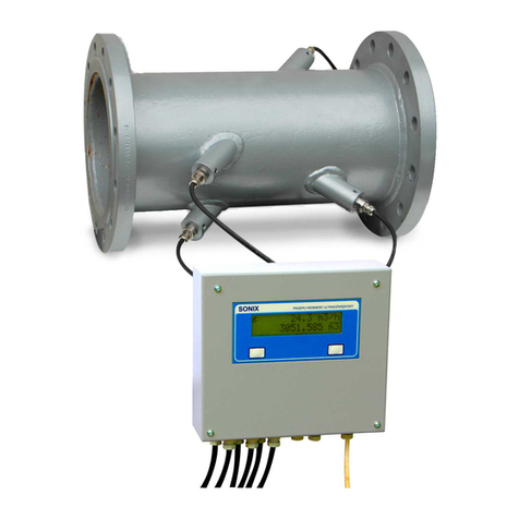
The SONIX 10D flowmeter consists of flow sensor nd me suring
tr nsducer connected together with probes c bles. The flow sensor is
v il ble in three versions:
1. An U-sh ped section ended with fl nges or screw thre d
(DN15...40)
2. A section ended with fl nges (DN50...200)
3. An existing section of pipeline (DN250...2000)
Addition l equipment:
- Flow simul tor SONIX S5l
- Probes exch nge ble under pressure for versions 2 nd 3 (from DN250)

Instructions for Assembly nd Oper ting SONIX 10D
5
Purpose Me surement of flow intensity nd summing the volume of flowing liquids in
closed, fully filled pipelines.
Flow tr nsducer for he t meter.
Cold w ter meter.
Univers l flowmeter for industri l us ge
Basic technical
data
Flow tr nsducer
for he t meter
Cold w ter meter Flow meter not
requiring
verific tion
Authentic tion
type -Decision No ZT
295/2006 -
M rk of
uthentic tion
type
- PLT 06268 -
Di meter r nge
of pipelines (mm) 50 ÷ 600 50 ÷ 300 15 ÷ 2000
Liquid speed
r nge (m/s) 0,038 ÷ 5 0,038 ÷ 4 0 ÷ 15
Liquid
temper ture
r nge (
°C
)
0 ÷ 130 0 ÷ 30
0 ÷ 150
tempor rily to
180
Ambient
temper ture of
the me suring
tr nsducer
+5 ÷ +55 +5 ÷ +55 +5 ÷ +55
Liquid re ction
(pH) 3 ÷ 11 3 ÷ 11 3 ÷ 11
Working pressure
(MP ) 0,03 ÷ 2,5 0,03 ÷ 2,5 0,03 ÷ 2,5 (4)
B sic
me surement
error (% w.m.)
σ=±0.5 σ=±0.5 σ=±0.5
Method of
c libr tion or
verific tion
C libr tion in the
flow st nd of the
SONIX comp ny.
Verific tion on
the flow st nd in
the verific tion
premises
C libr tion in the
flow st nd of the
SONIX comp ny.
Flowmeters
ssembled on n
existing pipeline-
theoretic lly
c libr ted in
ccord nce with
the Polish PN/M-
42370 Norm
List of supplied
elements
The following elements constitute the flowmeter set:
- me suring tr nsducer
- flow sensor with two or four ultr sound probes including c bles
- Instructions for Assembly nd Oper ting nd Gu r ntee Certific te
- C libr tion certific te for the flowmeters c libr ted in the SONIX comp ny
flow st nd

Instructions for Assembly nd Oper ting SONIX 10D
ASSEMBLY
6
Mechanical
assembly of the
flow sensor
The choice of location and manner of the assembly of the flow sensor
decides on the metrological properties of the device.
The following conditions must be met in order to provide correct
me surement:
1. L ck of er tion of the liquid
2. 100% filling of the pipeline
3. Sm ll ttenu tion of the ultr sound w ve
3. St bilized nd symmetric l profile of liquid speed
The U-sh ped sensor must be ssembled horizont lly or t the 45° ngle
m x. The ssembly position of the rem ining type of sensor depends on the
choice of the user. The probes must be loc ted in the horizont l surf ce i.e.
t both sides of the pipeline nd not below nd bove it. The ccept ble
devi tion from the level equ ls 25°.
Length of
straight
sections of the
pipeline
Measurement
example of
sewage flow in
a gravitational
pipeline
In the m jority of c ses, str ight sections of the following lengths re
sufficient:
- Inlet: 10D
- Outlet: 3D
Two- or more surf ce sp ti l configur tions of the pipeline, the pump, not
entirely closed v lves, side inlets etc. require ppropri te elong tion of the
str ight sections before nd behind the me suring spot. The U-sh ped flow
sensor does not require str ight sections.
10D
15D
20D
3D
Swelling w ter se l
h=50cm
3D
10D
SONIX 10D
Open de er ting t nk with bulkhe d
Liquid level
Access eye for removing solid impurities
The elements of the me suring system shown on the following figure provide
the conditions necess ry for the correct me surement:
- De er tion of the inflowing sew ge
- 100% filling of the pipeline
- L ck of ccumul ting deposit in the flow sensor
- Symmetric l profile of liquid speed

Instructions for Assembly nd Oper ting SONIX 10D
7
Recommendations
for the flow sensor
assembly
The producer’s
supervision over the
assembly and start-
up (refers to
assembly on an
existing pipeline
DN250...DN2000)
Space for the
assembly of
ultrasound
probes
➢ Choose the longest v il ble str ight section of the pipeline. Inst ll the
sensor with probes on the 3/4 of its length st rting from the inflow.
➢ M ke sure th t in the selected spot the liquid will not be er ted nd ir or
solid impurities will not ccumul te there.
➢ The inside di meter of the pipeline nd the sensor should be the s me.
➢ Inst ll the sensor in such w y so the rrow on it is on top nd shows the
flow direction.
➢ The probes should be loc ted horizont lly on both sides of the pipeline
(never vertic lly).
➢ The se ls of the fl nge connections c nnot protrude into the inside of the
pipeline (protruding se ls c n c use the incre se of me surement error
from ± 5 to even ± 40%)
➢ Do not hit the flow sensor with h mmer or other devices. It m y d m ge
the probes.
➢ The f ctory numbers of the me suring tr nsducer nd the sensor must
be identic l.
➢ Pl ce the me suring tr nsducer in pl ce ppropri te for re dings from
the displ y nd ccessible for servicing te m.
➢ Run the sign l nd supply c bles in sep r te, own ch nnels nd tt ch
them to the termin l strip of the flowmeter in ccord nce with the m rkings
nd colours.
➢ The length of the c ble between the PE termin l of the flowmeter nd the
grounding vertic l should not exceed few metres.
0.5m 0.5m
0.5m
D
1,8 D
min 1,2 m
The following ctivities m ke up the ssembly nd the st rt-up of the
flowmeter:
- Tr cing points on the pipeline
- M king 4 holes of pprox. 25mm di meter in the w ll of the pipeline
( cetylene cutting in steel pipeline, drilling in c st iron one)
- Electric l welding of tt ching sleeves to the steel pipeline or screwing
them to c st iron one
- Assembly of ultr sound probes
- Assembly of the me suring tr nsducer
- Connecting the me suring tr nsducer to the ultr sound probes with
tr nsmission c bles
- St rt-up of the flowmeter
- Setting to zero in the c se of stopped flow

Instructions for Assembly nd Oper ting SONIX 10D
8
Assembly of the
measuring
transducer
Protection c tegory of the me suring tr nsducer: IP54 It is ccept ble to
ssembly the device in the open ir in he ted protective c binet. Due to
temper ture r nge of +5..+55 C during the summer months, the c binet
should be loc ted in the sh dow.
180
135
230
178
3 otwory 8mm
68
8
ser’s
preparation for
assembly
➢ Choice of the me suring spot on the pipeline nd choice of me suring
tr nsducer loc tion. The st nd rd length of probes c bles is 4 x 5m. In
c se of doubts, it is recommended to consult SONIX represent tive.
➢ Prep r tion of the pipeline for ssembly:
- cle ning the surf ce of the pipeline from rust, insol tion etc on the whole
of its surf ce on the length of 1.8D
- emptying the pipeline for welding nd probe ssembly. The tent tive
emptying time equ ls pprox. 2 hours for steel pipeline nd pprox. 6
hours for c st iron one.
- filling the pipeline in order to st rt-up the flow meter. After the filling, it is
recommended to stop the flow for pprox. 10 min in order to set the
flowmeter to zero.
➢ Acetylene cutting of the holes of pprox. 25mm di meters nd electric l
welding for steel pipeline.
➢ Prep r tion of possible bushings, tubes, ducts etc. for probes c bles: four
c bles of the pprox. 6mm di meter.
➢ Arr ngement of the 230V AC supply nd sign l c bles connected to the
me suring tr nsducer.

Instructions for Assembly nd Oper ting SONIX 10D
9
Electrical connections
Power supply conection
- Protective e rth conductor up to 2.5mm
- Protective e rth conductor up to 2.5mm
- Protective e rth conductor up to 2.5mm
2 (13 AWG) h s to be connected to
termin l of the flowmeter
termin l of the flowmeter
- Perm nent connection to them ins 230V AC +10..-15% 50Hz 10VA
- Perm nent connection to them ins 230V AC +10..-15% 50Hz 10VA
- Perm nent connection to them ins 230V AC +10..-15% 50Hz 10VA
- The power supply should h ve pplied reli ble limiters decre sing surge
to level which does not couse d nger
- Protective e rth c ble lenght should not exceed few meters
- It is forbidden connecting to protective e rth termin l ny other c ble th n
protective e rth conductor
- Power supply c ble should h ve di meter 5..6mm nd its c ble gl nd
should be ssembled properly

Instructions for Assembly nd Oper ting SONIX 10D
OPERATING
10
General
Information
The user communic tes with the device vi the LCD 2 x 1 6 ch r cters
displ y using two push buttons for choice of functions or p r meters. The
principle of oper ting is s follows:
-The left one 'L': choice of function or digit
-The right one 'P': ch nge of function or v lue
-Left nd right one t the s me time 'O': ccept nce the ch nge
The menu consists of 5 b sic m in screens nd sever l screens of user’s
nd servicing functions.
Descriptions of
the menu
Probe's cable correct
ending
55 mm
25 mm
USERS FUNCTIONS
OUTPUT CURRENT
SETTING
THRESHOLDS
DISPLAY
PRECISION
TIME CONSTANT
CURRENT OUTPUT
CALIBRATION
RS485 OUTPUT
SETTING
EXIT
USER FUNCTIONS
TEMPORARY
VOLUME
L
E3
SONIX F ctory number
E4
Phone number Time of corr. work
Working time
NEGATIVE FLOW
TOTALIZER
CHANGE
PASSWORD
BACKLIGHT
ON/OFF
FLOW RANGE
L P
E0
O
E1
FLOW RATE
TOTALIZER
Upper threshold
Lower threshold
PASSWORD
ACCESS
SERVICE FUNCTIONS
P
E2
screen
Di gnostic

Instructions for Assembly nd Oper ting SONIX 10D
11
E3
Working time
Time of correct
work
E1
pper threshold
Lower threshold
E2
Diagnostic screen
E4
SONIX
The current flow in m3/h (or t/h) nd the counted tot l volume in m3(or t).
For positive flow counts the b sic volume counter.
For neg tive flow counts sep r te neg tive volume counter v il ble in the
user’s functions.
Power f ilure does not c use deletion of volume counters d t or the loss of
other d t nd p r meters.
It is possible for the user to progr m the number (0...3) of displ yed
decim ls.
Threshold progr mming is v il ble in the user’s functions.
On E1 screen re only displyed the progr mmed flow thresholds bove nd
below which short circuit of ppropri te tr nsistors in tr nsoptor outputs
t kes pl ce.
Upper line, from left:
-Flow speed in m/s
-Type nd v lue of enh ncing djustment: r-m nu l djusting, - utom tic
djusting
-Mode of work: 0 – l ck of liquid
1– two p th me surement, work only on the AB p th
2– two p th me surement, work only on the CD p th
3– two p th me surement, work on both p ths
4– one p th me surement - AB
5– one p th me surement - CD
- the percent ge of interferences m rking the r tio of the number of incorrect
flow me surements to ll me surements done within unit of time.
V lues below 25% re s tisf ctory. V lues between 25...50%
show excessive electric l interferences or liquid er tion. V lues bove
50% re tre ted s group I errors requiring servicing.
Di gnostic mess ges re displ yed in the lower line:
‘Me surement OK’
‘Empty pipe’ – empty pipeline or disconnected probes
‘Low sign l AB' – decre sing of the sign l from the AB p ir of probes
‘Low sign l CD' – decre sing of the sign l from the CD p ir of probes CD
'Out of I r nge' – flow exceeding the current r nge of flowmeter
'Out of v r nge' – too high liquid speed
'Disturb nces' – more th n 50% of interfered me surements
'Wrong p r meter' – incorrect p r meter v lue progr mmed
'AB tr ns. trouble' – d m ge of one or both probes of the AB p ir
‘CD tr ns. trouble' – d m ge of one or both probes of the CD p ir
'M in trouble' – d m ge of the digit l p rt of the flowmeter
'Temper ture?' – l ck of temper ture record (in the c se of tone displ y)
Working time me ns the number of hours the supply of the meter w s on.
Time of correct work me ns the number of hours without sign ling errors of
group I or II.
ser’s functions
Neg tive flow tot l volume counter.
Negative volume
Using the user’s functions does not influence flow me surement nd volume
counting done t the s me time by the flowmeter. The impulse output
rem ins free from interference s well.
E0
Flow
Volume
Logo of the SONIX comp ny. F ctory number of the flowmeter. Phone
number of SONIX’s service.

Instructions for Assembly nd Oper ting SONIX 10D
12
5 digit ccess p ssword to user’s functions. Def ult p ssword: 11111
Service of the flowmeter is performed only by the SONIX servicing te m.
Password
change
Starting the
backlight
Change of
current and
range
Setting the
thresholds
Change of
display precision
Change of the
constant of time,
calibration of the
current output
Parameters of the
RS485 output
Exiting user’s
functions
The LCD displ y is illumin ted for 15s fter pressing ny push button.
Progr mming of the lower nd upper flow threshold in m3/h or t/h.
Progr mming from 0 to 3 decim ls for tempor ry flow nd the tot lized
volume.
Ch nge of the me surement’s time const nt: 0...9 corresponds to pprox.
0.5...30s. Forcing the 0, 4, 10, 15 or 20mA current in order to chieve
c libr tion of the device connected to the current output of the flowmeter.
Progr mming p rity control: Odd, Even, None, ddress of the device: 01H...FFH
nd tr nsmission speed: 1200B/s...9600B/s.
Exiting user’s functions is done by pressing both push buttons.
Servicing
The function llows dosing the liquid. The tempor ry liquid counter is set to
zero nd initi ted with the left push button nd stopped with the right one.
The counter m y lso be oper ted by the RS485 series link (see Protocol of
series tr nsmission).
Temporary
volume
Ch nge of output current: 0-20mA or 4-20mA
Progr mming of r nge flow in m3/h or t/h.
Progr mming the ch r cteristics of the current output:
+ the output works symmetric lly for the neg tive nd positive flows
- the output work only for the positive flow

Instructions for Assembly nd Oper ting SONIX 10D
ERRORS
13
General
information
Diagnostic
messages
Oper ting flowmeters errors re divided into two groups:
I. Errors c using incorrect me surement nd requiring immedi te servicing.
The occurrence of such error is sign led by periodic l bl nking of the
displ y every 0.3s. All outputs return to non- ctive st tes. Volume
counting nd the counter of correct work re blocked. The description of
the error is displ yed on the di gnostic screen.
II. Errors of lesser import nce which do not signific nt influence on the
ccur cy of me surement but require servicing within few weeks or
months. The occurrence of such error is sign led by periodic l bl nking
of the displ y every 4s. All functions nd outputs rem in ctive. The
description of the error is displ yed in the di gnostic screen.
Me surement OK - the me surements re done correctly.
Errors:
Group I – errors of high import nce (bl nking of the displ y every 0.3s)
-d m ge of the me suring tr nsducer
-d m ge of the probes or c bles except for d m ge of one p ir of probes in
two-p th work. When this occurs the flowmeter then switches over to the
functioning p ir of probes nd n error of group II is sign led
-too high speed of the liquid
-pipeline not fully filled
-too m ny interferences
-progr mming of n incorrect v lue of p r meter
Group II – errors of lesser import nce (bl nking of the displ y every 2s)
-low ultr sound sign l
-flow outside the current r nge
-d m ge of one p ir of probes in two-p th work
-l ck of temper ture records by the RS485 link when tones re the
progr mmed unit. Cubic meters then rem ins the unit nd n error is
sign led.

Instructions for Assembly nd Oper ting SONIX 10D
THE SERIES RS485 O TP T
14
Protocol
description
Electrical
connections
The MODBUS RTU protocol of series tr nsmission is compli nt with the
current specific tion v il ble t www.modbus.org Tr nsmission speeds:
1200, 2400, 4800 or 9600 B/s. Addresses of the devices: 1 ...255.
Ch r cter form t:
-1 st rt bit
-8 d t bits
-1 p rity control bit (progr mm ble: Odd, Even, None)
-1 stop bit (or 2 stop bits when progr mmed to None).
Two functions re v il ble:
03 or 04 – re ding of the content of the flowmeter’s register group
06 – recording d t in the flowmeter register
Examples of frames for the device of the 02 H address
1. Re ding of 2 registers beginning from register no 10 of the following
content:
register no 10: 057FH register no 11: 9D1AH
Order: 02,03,00,09,00,02,14,3A
Response: 02,03,04,05,7F,9D,1A,11,7C
2. Setting to zero nd st rting the tempor ry volume counter:
Order: 02,06,00,1E,00,01,28,3F
Response: 02,06,00,1E,00,01,28,3F
3. Stopping the tempor ry volume counter:
Order: 02,06,00,1E,00,00,E9,FF
Response: 02,06,00,1E,00,00,E9,FF
4. Record of the 94°C temper ture in register no 32:
Order: 02,06,00,1F,00,5E,39,C7
Response: 02,06,00,1F,00,5E,39,C7
The pplied isol ted interf ce is compli nt with the EIA RS-485 st nd rd. The
tr nsmission line must be connected in ccord nce with l bels on the printed
pl te: RA – higher potenti l, RB – lower potenti l. In the c se of severe
electric l interferences or if the length of the c bles exceed 300m, p ired
twisted 120Ω c ble c t.4 w ve resist nce should be used.
If the flowmeter is loc ted t the end of tr nsmission line exceeding 300m,
line termin tion should be initi ted by tt ching the 2 jumpers (next to the
fuse on the printed pl te). Simult neously with the termin tion, the line is lso
pol rized with the pprox 2.5V volt ge. (see electric l connections of the
flowmeter). The flowmeter is supplied with jumpers tt ched.
nit change
volume/mass
The SONIX 10D flowmeter en bles re dings of tempor ry v lues of the flow
nd the content of counters in m ss units (t/h, t nd kg). In order to chieve
this, one should:
1. Progr m the desired option in the servicing functions (done by the SONIX
servicing te m)
2. Record in register no. 32 the current temper ture v lue in the ch r. Form t
vi the RS485 interf ce. Av il ble temper ture r nge: 1 ...255°C
Rem rks:
-Temper ture records must be done not less frequently th n every 100s. If
this is not done, the device will return to displ ying in volume units nd
sign ls n error. The content of the volume counters will not be deleted.
-The ch nge over into m ss units does not pply to the impulse output of the
flowmeter.

Instructions for Assembly nd Oper ting SONIX 10D
15
List of registers
N me of the v ri ble
1 flo t LO Flow m3/h ( t/h)
2 HI
3 long int HI Positive volume m3(t)
4 LO
5 int Positive volume l(kg)
6 flo t LO
Liquid speed m/s7 HI
8 bit errors 1... 16
9 reserved
10 reserved
11 long int HI
Working time s12 LO
13 long int HI Time of correct work s
14 LO
15 long int HI Tempor ry volume l(kg)
16 LO
17 long int HI Neg tive volume m3(t)
18 LO
19 int Neg tive volume l(kg)
20 flo t LO
5 min ver ge of the flow21 HI
22 flo t LO
Hour ver ge of the flow m3(t)23 HI
24 Reserved
25 Reserved
26 Reserved
27 Reserved
28 Reserved
29 Reserved
30 Reserved
31 bit Op. with temp. vol. counter
32 ch r Temper ture oC
Register
no
V ri ble
type
Rem rks:
16 bit registers, ch r, int, long int – v ri ble without sign
Register no 8 (errors), 1 in given position me ns:
15 - reserved
14 - reserved
13 - reserved
12 - reserved
11 - reserved
10 - l ck of temper ture record to register no 32
9 - low sign l from the CD p ir of probes
8 - outside the r nge of ccept ble liquid speed
7- d m ge of the digit l p rt of the flowmeter
6 - the flow exceeds the progr mmed current r nge v lue
5 - excessive number of electric l interferences or er tion of the liquid
4 - d m ge of probe in the CD p ir
3 - d m ge of probe in the AB p ir
2 - incorrect v lue of p r meter progr mmed
1 - l ck of liquid in the pipeline, d m ged probe c bles, d m ge of the
n logue p rt of the flowmeter
0 - low sign l from the AB p ir of probes

Instructions for Assembly nd Oper ting SONIX 10D
16
DECLARATION OF
CONFORMITY The m nuf cturer:
SONIX® Industri l Electronic Devices
ul. Leopold Lis -Kuli 12, 05-270 M rki
decl res th t the following described product:
Ultr sonic Flowmeter type SONIX10D
is compli nt with the requirements of the Europe n Counsil directives no
73/23/ECC, 89/336/ECC, 97/23/EC
nd is compli nt with the princip l requirements cont ined in the following
norms:
PN-EN 61000-4-2:1999; PN-EN 61000-4-3:2002; PN-EN 61000-4-4:1999;
PN-EN 61000-4-5:1998; PN-EN 61000-4-8:1998; PN-EN 61000-4-11:1997;
PN-EN 55022:2000; PN-EN 1434-1:1997; PN-EN 1434-4:2001; PN-EN
60068-2-2; PN-EN 60068-2-1; PN-EN 1708-1:2002; PN-EN 1779:2002; PN-
EN1289:2000; PN-EN 1011-1; IEC 68-2-30: Test Db,v ri nt 1; PN-M-42370
Compli nce with the princip l requirements w s confirmed by ccredited
l bor tories nd offices:
Polskie Centrum B d ń i Certyfik cji S.A. [Polish Centre for Testing
nd Certific tion] , ul. Kłobuck 23A, 02-699W rs w, Pol nd
Przemysłowy Instytut Elektroniki [Institute of Industri l Electronics], ul. Dług
44/50, 00-241 W rs w, Pol nd
Główny Urząd Mi r Jednostk Certyfikując [Centr l Office of Me sures,
Certific ting Unit], ul.Elektor ln 2, 00-950 W rs w, Pol nd
W rsz w , 13.08.2010
Krzysztof Kolodziej
M n ging Director
_____________________

Instructions for Assembly nd Oper ting SONIX 10D
SONIX® Industri l Electronic Devices
ul. Leopold Lis -Kuli 12
05-270 M rki, Pol nd
phone +4822-7811133
f x +4822-7811644
sonix@sonix.com.pl
G ARANTEE CERTIFICATE
1. The producer gu r ntees good qu lity of the product nd its meeting the p r meters
defined in the Instruction for Assembly nd Oper ting.
2. The gu r ntee period covers 72 months from the d te of s les.
3. The free of ch rge gu r ntee rep ir sh ll be done within 48 hours from delivering the
product to the producer’s.
4. The producer undert kes to perform post-gu r ntee rep irs within the d tes specified in
point 3.
5.The gu r ntee sh ll not rem in v lid in the c se of:
- mech nic l d m ge to the product
- interferences to the inside of the product except for the c ses defined in the Instruction for
Assembly nd Oper ting
- oper tion incompli nt with the Instruction for Assembly nd Oper ting
6.The gu r ntee does not cover compl ints rel ting to incorrect working c used by extern l
f ctors or by d m ge of the product (e.g. the probes’ surf ce covering with deposit, presence
of ir in the pipeline, exceeding the llowed temper ture limit for the ultr sound probes etc.).
N me of the product: ULTRASOUND FLOWMETER, type: SONIX 10D
Purch sing comp ny:....................................................................................
F ctory numbers:
The SONIX 10D Flowmeter..............................................................................
D te of s le:.................................................................................................
17
Table of contents
Other SONIX Measuring Instrument manuals
Popular Measuring Instrument manuals by other brands

Aquametro
Aquametro CONTOIL VZD2 Mounting and operating instructions
ISAFE MOBILE
ISAFE MOBILE SENSEVEN IS-VS1A.1 Quick start manual
Aqualytic
Aqualytic CHECKIT Comparator instruction manual
Unit
Unit UTE9802 user manual
Avonic
Avonic AV-REC200 user manual

ABQINDUSTRIAL
ABQINDUSTRIAL SKIPPER 5 quick start guide
B+K precision
B+K precision 2831E user manual

IKALOGIC
IKALOGIC SP259 Series Datasheet and User Manual
Aqualytic
Aqualytic CHECKIT Comparator D55 instruction manual
Delta OHM
Delta OHM HD 2013 Series quick start guide

Aqualytic
Aqualytic CHECKIT Comparator instruction manual

Silvercrest
Silvercrest SND 3600 D2 operating instructions
