SIKA MC 75.2 User manual

Please keep this operating manual for future reference.
If the device is resold, please provide the operating manual along with it.
© SIKA •Ba_MC75.2_en •03/2017 .
Multifunction simulator
Type MC 75.2
Operating manual
(Translation)
Operating manual ....................................................page 1 - 64

MC 75.2
- 2 - © SIKA •Ba_MC75.2_en •03/2017
Table of contents page
0About this operating manual.........................................................................................4
1General ..........................................................................................................................7
1.1 Introduction .................................................................................................................7
1.1.1 About this guide ......................................................................................................8
1.2 Instrument...................................................................................................................8
1.2.1 General view of the unit ..........................................................................................8
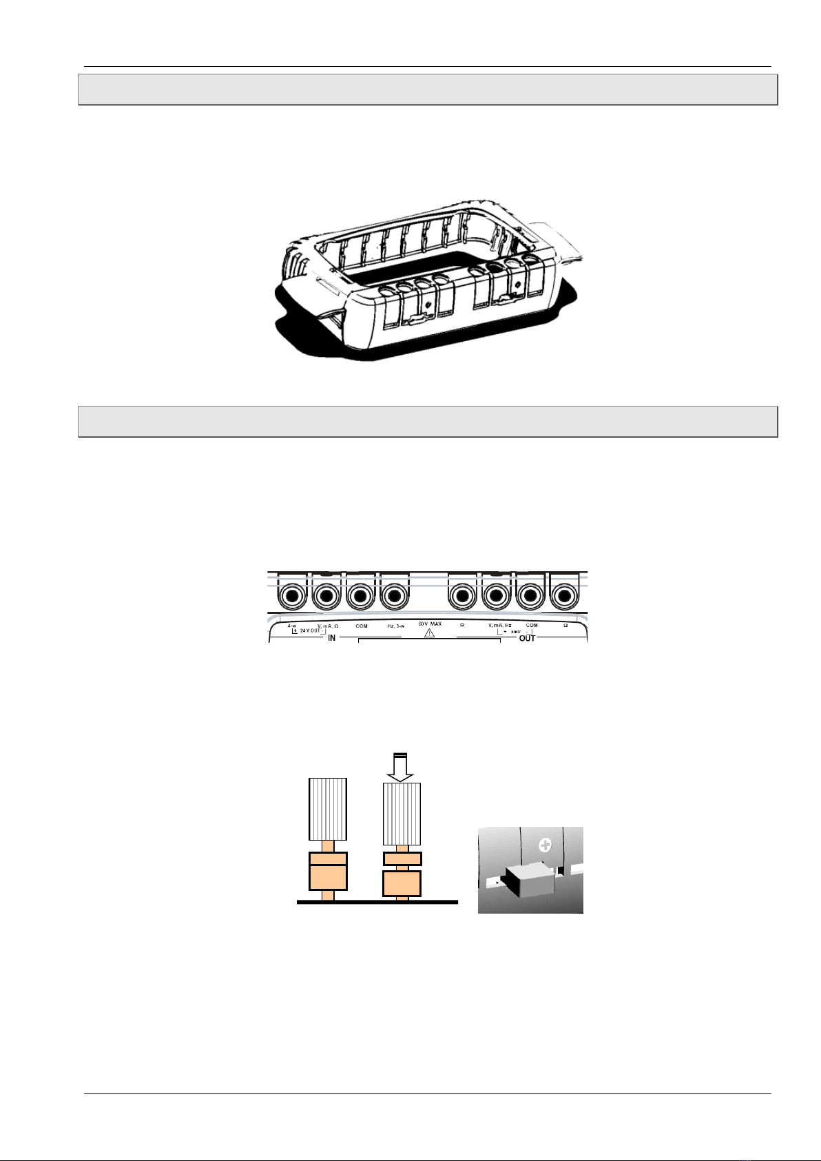
1.2.2 Housing ...................................................................................................................9
1.2.3 Connection terminals .............................................................................................9
1.2.4 Side connectors ....................................................................................................10
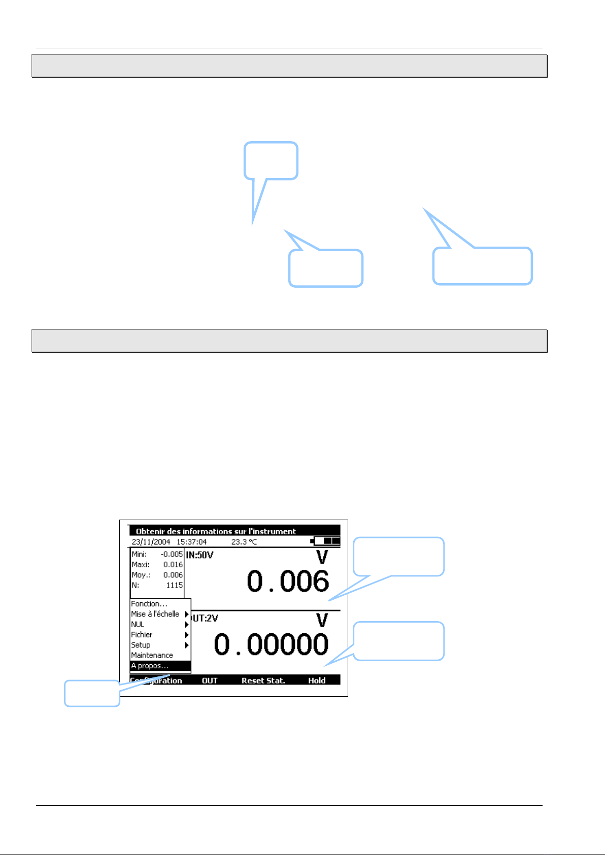
1.2.5 Screen ...................................................................................................................10
1.2.6 Keyboard ...............................................................................................................11
1.2.7 Batteries and charger...........................................................................................12
1.2.8 Sand and Strap......................................................................................................12
1.3 General description...................................................................................................13
1.3.1 User Interface .......................................................................................................14
1.4 Safety.........................................................................................................................17
1.4.1 Compliance with safety standards .......................................................................17
1.4.2 Instructions ...........................................................................................................17
1.4.3 Making measurements.........................................................................................17
1.4.4 Unusual faults and stresses.................................................................................18
1.4.5 Definitions .............................................................................................................18
1.5 Service.......................................................................................................................19
1.5.1 Maintenance menu ...............................................................................................19
1.5.2 Cleaning ................................................................................................................19
2Getting started.............................................................................................................20
2.1 Powering on...............................................................................................................20
2.2 Measurement ............................................................................................................21
2.2.1 Voltage measurement (DC) ..................................................................................22
2.2.2 Current measuring (DC) .......................................................................................22
2.2.3 Resistance measuring ..........................................................................................25
2.2.4 Continuity test .......................................................................................................25
2.2.5 Frequency measuring (signal)..............................................................................26
2.2.6 Frequency measuring (dry contact) .....................................................................26
2.2.7 Pulse counting ......................................................................................................26
2.2.8 Temperature measurement (RTD).......................................................................27
2.2.9 Temperature measurement (Thermocouple) ......................................................28
2.2.10 Pressure measuring.............................................................................................28
2.2.11 Pressure switch test.............................................................................................29
2.3 Generation / Simulation ............................................................................................30
2.3.1 Voltage generation (DC)........................................................................................31
2.3.2 Current generation (DC) .......................................................................................31
2.3.3 Resistance generation ..........................................................................................32

MC 75.2
Technical changes reserved - 3 -
2.3.4 Temperature simulation (RTD).............................................................................33
2.3.5 Temperature simulation (Thermocouple) ............................................................33
2.3.6 Frequency generation (signal)..............................................................................34
2.3.7 Frequency generation (dry contact) .....................................................................34
2.3.8 Pulse generation...................................................................................................35
3Advanced Operation.....................................................................................................36
3.1 Simulation Modes......................................................................................................36
3.1.1 Manual Editing ......................................................................................................36
3.1.2 Incremental Editing ..............................................................................................37
3.1.3 Predefined Settings ..............................................................................................37
3.1.4 Steps......................................................................................................................38
3.1.5 Simple Ramp.........................................................................................................39
3.1.6 Cyclic Ramp...........................................................................................................40
3.1.7 Synthesiser ...........................................................................................................41
3.1.8 Transmitter Mode .................................................................................................42
3.2 Scaling .......................................................................................................................43
3.3 NULL / Tare / Offset ..................................................................................................44
3.4 Calibrated sensors ....................................................................................................45
3.5 Calibration procedure ...............................................................................................47
3.6 Memory functions......................................................................................................50
3.7 Customer specific configurations .............................................................................53
3.8 Instrument Setup ......................................................................................................54
3.8.1 Contrast.................................................................................................................54
3.8.2 Date and Time .......................................................................................................54
3.8.3 Preferences...........................................................................................................55
4Technical Specifications..............................................................................................56
4.1 Measurement Function .............................................................................................56
4.1.1 Current measurement (DC)..................................................................................56
4.1.2 Current measurement (DC)..................................................................................56
4.1.3 Resistance measurement.....................................................................................57
4.1.4 Temperature measurement (Thermocouples) ....................................................57
4.1.5 Temperature measurement (RTD) .......................................................................58
4.1.6 Frequency measurement and counting ...............................................................59
4.1.7 Additional features at measurement mode .........................................................59
4.2 Transmission / simulation function ..........................................................................60
4.2.1 Voltage generation (DC)........................................................................................60
4.2.2 Current generation (DC) .......................................................................................60
4.2.3 Resistance generation ..........................................................................................60
4.2.4 Temperature simulation (Thermocouple) ............................................................60
4.2.5 Temperature simulation (RTDs) ...........................................................................62
4.2.6 Frequency- and pulses generation.......................................................................62
4.2.7 Additional features at simulation mode ...............................................................63

About this operating manual MC 75.2
- 4 - © SIKA •Ba_MC75.2_en •03/2017
0About this operating manual
•The operating manual is aimed at specialists and semi-skilled personnel.
•Before each step, read through the relevant advice carefully and keep to the specified
order.
•Thoroughly read and understand the information in the section "Safety".
If you have any problems or questions, please contact your supplier or contact us directly
at:
Dr. Siebert & Kühn GmbH & Co. KG
Struthweg 7-9 • D - 34260 Kaufungen
05605-803 0 • 05605-803 54
info@sika.net • www.sika.net
Hazard signs and other symbols used:
CAUTION! Electric current!
This sign indicates dangers which could arise from handling of electric current.
WARNING! / CAUTION! Risk of injury!
This sign indicates dangers that cause personal injuries that can lead to health defects or
cause considerable damage to property.
CAUTION! Material damage!
This sign indicates actions which could lead to possible damage to material or environmental
damage.
ADHERE TO OPERATING MANUAL!
NOTICE!
This symbol indicates important notices,
tips or information.
NO DOMESTIC WASTE!
The device must not be disposed of to-
gether with domestic waste.
Pay attention to and comply with infor-
mation that is marked with this symbol.
Follow the specified instructions and steps.
Adhere to the given order.
Check the specified points or notices.
Reference to another section, document or
source.
•Item.
Copyright notice:
The reproduction, distribution and utilization of this operating manual as well as the communication of
its contents to others without express authorization is prohibited. Offenders will be held liable for the
payment of damages. All rights reserved in the
event of the grant of a patent, utility model or design.

MC 75.2 About this operating manual
Technical changes reserved - 5 -
We are very grateful to you for choosing this SIKA accuracy measuring instrument which
benefits from our hundred years' experience in the manufacture of high quality, accuracy
measuring instruments. SIKA encourages your comments and would willingly accept any
suggestions from you to help us to perfect our know-how and improve our future products.
Because of this, we are able to continue our policy of continuous innovation which has served
our customers so well for the last 100 years.
LIMIT OF GUARANTEE / LIMIT OF RESPONSIBILITY:
SIKA guarantees the absence of faulty materials and the manufacture of this product under
normal conditions of use and maintenance. The guarantee period is one year and takes effect
on the date of delivery. Parts, repairs to the product and service are guaranteed for a period
of 90 days. This guarantee only applies to the original purchaser or the end user if he is a cli-
ent of a SIKA approved distributor and does not cover fuses, interchangeable batteries/cells
nor any product which, in the opinion of SIKA, has been badly handled, modified, neglected or
damaged by accident or subjected to abnormal conditions of use or handling. SIKA guaran-
tees that the software will function largely in accordance with its functional specifications for
a period of 90 days and that it has been correctly recorded on non-defective media. SIKA does
not guarantee that the software contains no errors or that it will operate without interruption.
SIKA approved distributors shall apply this guarantee to products sold to new clients it has not
served, but are not authorised to offer a longer or different guarantee in the name of SIKA.
Guarantee support is offered if the product was purchased by an intermediary from an SIKA
approved point of sale or if the purchaser has paid the applicable international price. SIKA
reserves the right to invoice the purchaser for the costs of importing, repair or replacement
parts if the product purchased in one country was sent to another country for repair.
The obligations under the guarantee of SIKA are limited at the discretion of SIKA, to reim-
bursement of the purchase price, or the free repair/replacement of a defective product re-
turned within the period of the guarantee to an SIKA approved service centre.
To claim for service under the guarantee, contact the nearest SIKA agent or send the prod-
uct, accompanied by a description of the problem, carriage and insurance paid (free on board
destination), to the nearest SIKA approved service centre. SIKA declines any responsibility in
the event of damage occurring during transportation. After repair under guarantee, the prod-
uct will be returned to the purchaser, carriage paid (free on board destination).
If SIKA considers that the problem was caused by abusive treatment, modification, an acci-
dent or abnormal conditions of operation or handling, SIKA will submit a quotation for the
cost of repair and will only commence the repair after receiving authorisation. After repair,
the product will be returned to the purchaser, carriage paid, and the costs of repair and
transportation will be invoiced to him.

About this operating manual MC 75.2
- 6 - © SIKA •Ba_MC75.2_en •03/2017
THIS GUARANTEE IS EXCLUSIVE AND REPLACES ANY OTHER GUARANTEES, EXPLICIT OR
IMPLIED, INCLUDING, BUT NOT LIMITED TO, ANY IMPLIED GUARANTEE AS TO THE
SUITABILITY OF THE PRODUCT TO BE SOLD OR APPLIED TO A PARTICULAR PURPOSE OR
USE. SIKA SHALL NOT BE HELD RESPONSIBLE FOR ANY PARTICULAR INDIRECT,
ACCIDENTAL OR CONSEQUENTIAL DAMAGE, NOR ANY CORRUPTED OR LOST DATA,
WHETHER AS A RESULT OF AN INFRACTION OF THE OBLIGATIONS OF THE GUARANTEE, OR
ON A CONTRACTUAL, EXTRA-CONTRACTUAL OR OTHER BASIS.
Because some countries or states do not permit limitations to an implied condition of guar-
antee, or the exclusion or limitation of accidental or consequential damage, the limitations
and exclusions of this guarantee may not apply to every purchaser. If any condition of this
guarantee is considered invalid or inapplicable by a competent court, such a decision will in
no way affect the validity or binding nature of any other condition.
Checks the package contents:
All MC 75.2 units are mechanically and electrically checked before delivery. The necessary
precautions have been taken to ensure that they reach the user undamaged.
However, it is a good idea to make a brief check for any damage that may have occurred dur-
ing transportation. If this is the case, make an immediate claim against the carrier.
The following accessories are standard:
•This user guide
•A mounting strap
•A protection cover
•Mains unit for charging the battery pack
•Test cables
•Test terminals
If the unit is to be returned, it is preferable to use the original packaging and state as clearly
as possible, in a note attached to the unit, the reasons for its return.

MC 75.2 General
Technical changes reserved - 7 -
1General
1.1 Introduction
The MC 75.2 is a multifunction calibrator. It is specially designed for calibration and mainte-
nance and can measure and simulate physical and electrical quantities, either on site or in
the laboratory.
It can perform all the following functions:
•Measure DC voltage and current, resistance and frequency / counts and pressure.
•Measure temperatures using thermocouples and resistive probes.
•Supply power and measure a current loop which is compatible with the HART®protocol.
•Generate DC voltages and currents.
•Simulate resistance, thermocouples and resistive probes.
•Recording of measurements and their display as a table or trend curve.
•Calibration and generation of the calibration report.
•Possibility of using calibrated sensors with memorisation of the calibration factors.
Measurement and transmission can take place simultaneously, with a double display.
In particular, it can calibrate air conditioning systems or transmitters by generating a signal
at the input to simulate a sensor and measuring the conversion current or voltage. Internal
software facilitates this operation, but it is also useful in other applications, notably in moni-
toring changes in physical quantities during processing, transformation phenomena, heat ex-
change, etc., either in development or quality testing.
The MC 75.2 has many associated functions that extend its range of application:
•Relative measurement.
•Results displayed based on a linear or other conversion law.
•Generation of increments and simple or cyclic ramps.
•Synthesis of curves.
A number of improvements have provided it with:
•Rapid access to all its functions.
•Intuitive user interface.
•Advanced on-line help system.
•Multi-functions keys defined step-by-step on the display.
•Connections which can be made with 4 mm safety plugs.
•Protection against overloads.
•Powered by a rechargeable battery with rapid internal charger.
The unit is enclosed in an ABS case with rubber sheath.

General MC 75.2
- 8 - © SIKA •Ba_MC75.2_en •03/2017
1.1.1 About this guide
This user guide consists of four parts: 1, 2, 3 and 4.
Part 1 contains general information and a description of the hardware and software of the
unit. It also contains a paragraph on safety and user precautions.
Part 2 contains brief handling information and a description of the various modes of opera-
tion.
Part 3 contains a description of the advanced functions.
Part 4 contains the technical specifications of the MC 75.2.
1.2 Instrument
General characteristics:
•Portable unit powered by a pack of Ni-MH, 1.8 Ah rechargeable batteries.
•Battery life: 5 to 10 hours, depending on the functions used.
•Stand for table mounting.
•Strap for carrying and on-site use.
•240 x 320 pixel liquid crystal graphical display.
•Choice of language for messages and programming the functions, settings and pa-
rameters using a keyboard with 22 keys.
•Back-lit display controllable from a key on the keyboard, with automatic switch-off af-
ter a programmable time of inactivity.
•Battery charging: mains adaptor supplied with the unit or from any 10 to 14 VDC power
supply.
•Adaptor characteristics: mains voltage 230 V ± 10%, 50/60 Hz.
•Charging time: maximum 3 h.
•ABS housing with rubber sheath.
•Dimensions: 210 mm x 110 mm x 50 mm.
•Weight: 900 g with housing and accessories.
•Waterproof to IP 54 in accordance with standard EN 60529.
1.2.1 General view of the unit

MC 75.2 General
Technical changes reserved - 9 -
1.2.2 Housing
The MC 75.2 is delivered with a rubber sheath fitted to the case. The sheath protects the unit
from mechanical shocks and makes the side openings for the USB interface connector and
the charger connector waterproof to IP54.
1.2.3 Connection terminals
Four terminals for connection for the "measurement" function ---IN---; two of which are re-
served for 3 or 4 wire connection when measuring resistance, temperature with a resistive
probe and current for a passive transmitter (§ 2.2).
Four connection terminals for the "transmit/simulate" function ---OUT--- (§ 2.2.3).
The 8 terminals of the MC 75.2 are of the "push & lock" type. They accept 4 mm banana
plugs, bare wires, spade terminals and miniature connectors for thermocouples.

General MC 75.2
- 10 - © SIKA •Ba_MC75.2_en •03/2017
1.2.4 Side connectors
There are two connectors on the left hand side of the unit.
•The first is a mains unit connector for battery charging.
•The second is a type B USB socket for connection to a computer.
The connector for the pressure sensor is located on the right-hand side of the unit.
1.2.5 Screen
The MC 75.2 is fitted with an LCD graphical display which is backlit with white LEDs. The res-
olution of the display is 240 x 320 pixels.
When the unit is in use, the screen comprises:
•A window displaying the programming of the "measurement" function parameters ---
IN--- (§ 2.2).
•A window displaying the programming of the parameters of the "transmis-
sion/simulation" function ---OUT--- (§ 2.2.3).
•A strip showing the various menus accessible by touch keys directly on the screen.
Measurement
Window
Simulation
Window
Menu
Pressure sensor
socket
USB
Socket
Charger
Socket

MC 75.2 General
Technical changes reserved - 11 -
1.2.6 Keyboard
The keyboard contains:
•4 blank function keys to select the various menus shown on the screen.
Note: for the purposes of this manual, the keys are referred to as F1, F2, F3 and F4 but
are not labelled on the unit.
•A navigator:
•A cancel key:
•A Start/stop key for the unit and back-lighting on/off key:
A short push switches the unit on. During operation, a short push switches the back-
lighting on or off. A long push of 2 seconds switches the unit off.
•12 alphanumeric keys for programming the parameters.
•An LED to indicate the state of charge of the battery:

General MC 75.2
- 12 - © SIKA •Ba_MC75.2_en •03/2017
1.2.7 Batteries and charger
The MC 75.2 contains a rechargeable NiMH battery pack. When the symbol blinks on the
display, the battery should be recharged as soon as possible.
•Insert the charger plug into the connector on the side of the unit (§ 1.2.4).
•Connect the charger to the mains after checking that the mains voltage is correct. The
charge indicator (red LED) on the front begins to blink if the battery level is very
low, then remains steady.
•Leave the charger switched on for about 3 hours.
•Disconnect the charger when the charge indicator on the front goes off.
The unit can be used while the batteries are charging.
CAUTION!
The charger can be used with voltages of 230 VAC.
The charger is for indoor use only, at an ambient temperature not exceeding 40°C
(104°F).
Only use the mains adaptor supplied with the calibrator.
Replacing the battery pack:
To replace the battery pack, contact your SIKA dealer.
1.2.8 Sand and Strap
The stand gives a good angle of view when the MC 75.2 is placed on a desk.
Unfold the stand on the back of the unit and
place the MC 75.2 on a desk (Fig.).
The MC 75.2 is supplied with an unbearable strap and two pins to attach the strap to the case.
Before attaching the strap, pass the free end through the
fixing loop as in the figure.
Feed the ends of the strap through the two slots on each
side of the case. Insert the two pins into the strap and pull
the strap to lock the pins in the case.

MC 75.2 General
Technical changes reserved - 13 -
1.3 General description
The diagram below briefly describes the functions of the firmware.
Starting
Measurement
Transmission
Maintenance
- Emission Modes
-Tare
- Scaling
-…
- Tare
- Scaling
-etc.
Configuration &
Parameters
The Start procedure checks that the unit is working correctly and initialises the various tasks
that are continuously executed during operation of the MC 75.2.
•The "Measurement" task is responsible for the configuration, post-processing and dis-
play of measurements.
•The "Transmission" task handles the various modes of simulation, pre-processing of set-
tings and the display.
•Several tasks are dedicated to setting parameters and configuration management.
•The "maintenance" task is responsible for calibration and initialisation of the unit.
A real time operating system coordinates the various tasks and manages the keyboard and
USB peripherals.

General MC 75.2
- 14 - © SIKA •Ba_MC75.2_en •03/2017
1.3.1 User Interface
The basic items forming the user interface are shown in the diagram below:
Date, Time &
Temperature
Description of the
current function
Battery
state
Measurement
Statistics
Transmission
Parameters
Main
Menu
Measurement
information
Emission
Information
Distinction
between IN
and OUT
Function
keys
The "on-line help" function is not visible in the menu, but is accessible at any time by press-
ing the key. When active, a help window for the function in use appears. The key
closes the help window and all the dialogue boxes displayed.
The main menu is located at the bottom of the screen, opposite the four function keys (F1 to
F4). To select an item from the menu, press the associated function key.
Navigation within menus and sub-menus is by means of the navigation keys and the ENTER
key.
For example, to display the % FS menu in the example of the screen below, perform the fol-
lowing steps:
1. Press the F4 key associated with the proposed Mode from the main menu.
2. Press the Down
navigation key twice to select the Predefined settings sub-menu and
confirm with the ENTER key.
3. Press the Down navigation key
once to select the % FS sub-menu and confirm with
the ENTER key. A dialogue box associated with this function appears and the four func-
tion keys change their function automatically to suit the dialogue box.
It is possible to cancel the selection at any time and return to the main menu by pressing the
ESC key.

MC 75.2 General
Technical changes reserved - 15 -
The dialogue box interface is intuitive.
It is managed by the function and navigation keys.
The tabulation key is used to select the next item from all the items in the dialogue box.
For example, to select the “Type of scale” field on the following screen, press the key
once.
The tabulation key functions cyclically, so that the first item follows the last.
The Right navigation key can replace the tabulation key.
The function key is used to display a drop-down list.
The key also closes an already open drop-down list.
The Up
and Down
navigation keys are used to select an item from an open list.
Confirm is by pressing the ENTER key.

General MC 75.2
- 16 - © SIKA •Ba_MC75.2_en •03/2017
There is a quicker way to select items from a drop-down list by using the Up/Down navigation
keys to select the next/previous item from the list without displaying the contents of the list.
For example, the state of the "Power supply loop" field can be changed from OFF to ON using
the Down and Up navigation keys.
During operation of the MC 75.2 , several symbols are displayed to simplify selection and in-
dication of the current functions.
These symbols are shown in the table below:
Symbol Description
Function keys
Tabulation key
Open a drop-down list
Close a drop-down list
Cancel the selected item
Stop the current transmission
Suspend the current transmission
Commence or resume transmission
Launch transmission in the increasing direction
Launch transmission in the decreasing direction
Transmit synthesised points in the order entered
Transmit synthesised points in the reverse order
Cancel the selection
Add the item being edited
Edit the selected item
Open a file
Indication symbols
Maintain transmission or display of measurements
Indication of battery state
HART compatibility is on
Loop power supply is on
Loop power supply is off
Square law scale is on
Warning: Out of Range or error
2 wire cabling detected
3 wire cabling detected
4 wire cabling detected

MC 75.2 General
Technical changes reserved - 17 -
Symbol Description
Indication symbols
Transmission in incremental mode
Transmission in staircase mode
Transmission in simple ramp mode
Transmission in cyclic ramp mode
Transmission in synthesiser mode
Transmission in% of Full Scale mode (% FS)
Transmission in valve test mode
Item already selected
Measurement smoothing is active
The Tare function is on
Setting to scale is on
Pulse transmission
Data recording (the value to the right indicates the number of values logged)
1.4 Safety
1.4.1 Compliance with safety standards
The unit is built and tested in accordance with European standard EN 61010-1: safety rules
for electronic measuring equipment.
These user instructions contain information and warning notices which must be respected by
the user for protection against danger from electric currents, ensuring correct operation of
the unit and protection against any false step that could damage the unit or make it unsafe to
use.
The unit may, when necessary, be subjected to temperatures of between -10°C and +55°C
without prejudicing safety.
1.4.2 Instructions
The unit is designed to be used in complete safety if the instructions given in the accompany-
ing documents are followed. Any use apart from those defined, may prejudice the safety of
the operator and is therefore dangerous and forbidden.
1.4.3 Making measurements
Measuring wires and leads must be in good condition and must be replaced if their insulation
appears defective (insulation cut, burned, etc.).
When the unit is connected to the measurement circuit, the terminals may be dangerous. Al-
so, never place your hands near a terminal, whether in use or not. This advice also applies to
the battery charger sockets and the USB link connected directly or indirectly to the terminals
of the unit. Any work on these circuits must be carried out with the unit disconnected from
any other external circuit.

General MC 75.2
- 18 - © SIKA •Ba_MC75.2_en •03/2017
Never exceed the limiting values of protection indicated in the specifications (§ 4).
When the order of magnitude of the value to be measured is unknown, make sure that the
starting measurement range is the highest possible, or choose the automatic range selection
mode.
Before changing the function, disconnect the wires for measuring the external circuit. When
measuring current and / or voltage, even if low, remember that the circuits may be live with
respect to earth, at a voltage that is dangerous for the operator.
Never carry out resistance measurements on a live circuit.
1.4.4 Unusual faults and stresses
Whenever it is believed that the protection has been damaged, switch off the unit and ensure
that it is not used prematurely.
The protection may have been damaged if, for example:
•There is obvious damage to the unit.
•The unit is no longer able to make accurate measurements.
•The unit has been stored under unfavourable conditions.
•The unit has been subjected to severe stress during transportation.
1.4.5 Definitions
Definition of the installation category
This is also known as the overvoltage category.
It is the classification of the installation according to standard limits for transient overvoltag-
es (standard CEI 664).
Table of symbols used
Symbol Description
Earth point
Complies with European Union directives

MC 75.2 General
Technical changes reserved - 19 -
1.5 Service
The MC 75.2 must always be set up according to the instructions in this notice. Incomplete or
poorly executed setting up may adversely affect the safety of the operator.
The responsible authority must ensure on a regular basis that factors affecting safety do not
change with time and carry out any necessary preventive work.
Before opening the MC 75.2 for any work, you must ensure that all wires are disconnected
from the unit.
Any adjustment, maintenance or repair of an open MC 75.2 must be avoided as far as possi-
ble and, if essential, must be carried out by qualified personnel who are familiar with the
risks involved.
1.5.1 Maintenance menu
This Menu is protected by a password and not accessible to the user.
Consult SIKA who will indicate the procedure to follow for maintenance services.
1.5.2 Cleaning
If the MC 75.2 needs cleaning, use a tissue soaked in a non-solvent cleaning solution. Switch
off the unit and wipe the sheath and keyboard if necessary. If any liquid enters the unit it may
cause irreparable damage.

Getting started MC 75.2
- 20 - © SIKA •Ba_MC75.2_en •03/2017
2Getting started
In order to use the MC 75.2 unit in complete safety, users must carefully read paragraph 1.4
(page 17) which, among other things, deals with safety before handling.
It is advisable also to read the following paragraphs:
§ 1.2.7 "Batteries and charger".
§ 1.5.2 "Cleaning".
2.1 Powering on
Connect the charger if this is the first time of use. The red LED lights while the battery
pack is charging. Wait until fully charged (LED off) before switching on the unit by pressing
the start / stop key for one second.
After starting, the MC 75.2 is set by default to voltage measurement and voltage transmis-
sion. Connect the Volts output to the Volts input as shown in the diagram below.
Check that the measurement displayed is the same as the simulated voltage.
To change the value of the simulated voltage, open the transmission window by pressing the
OUT function key (F2).
Enter a numerical value using the alpha-numeric keys and confirm with the ENTER key.
Table of contents
Other SIKA Test Equipment manuals
Popular Test Equipment manuals by other brands

Benning
Benning TRITEST easy operating manual

PeakTech
PeakTech 2680 Operation manual

Project Fire
Project Fire Zonecheck Instruction booklet

cctv camera pros
cctv camera pros MON-7HD user manual

YOKOGAWA
YOKOGAWA AQ1300 Series user manual

Walther
Walther E-boxx 780001502 Operating instruction and technical description