CB Radio DOSY Test Center
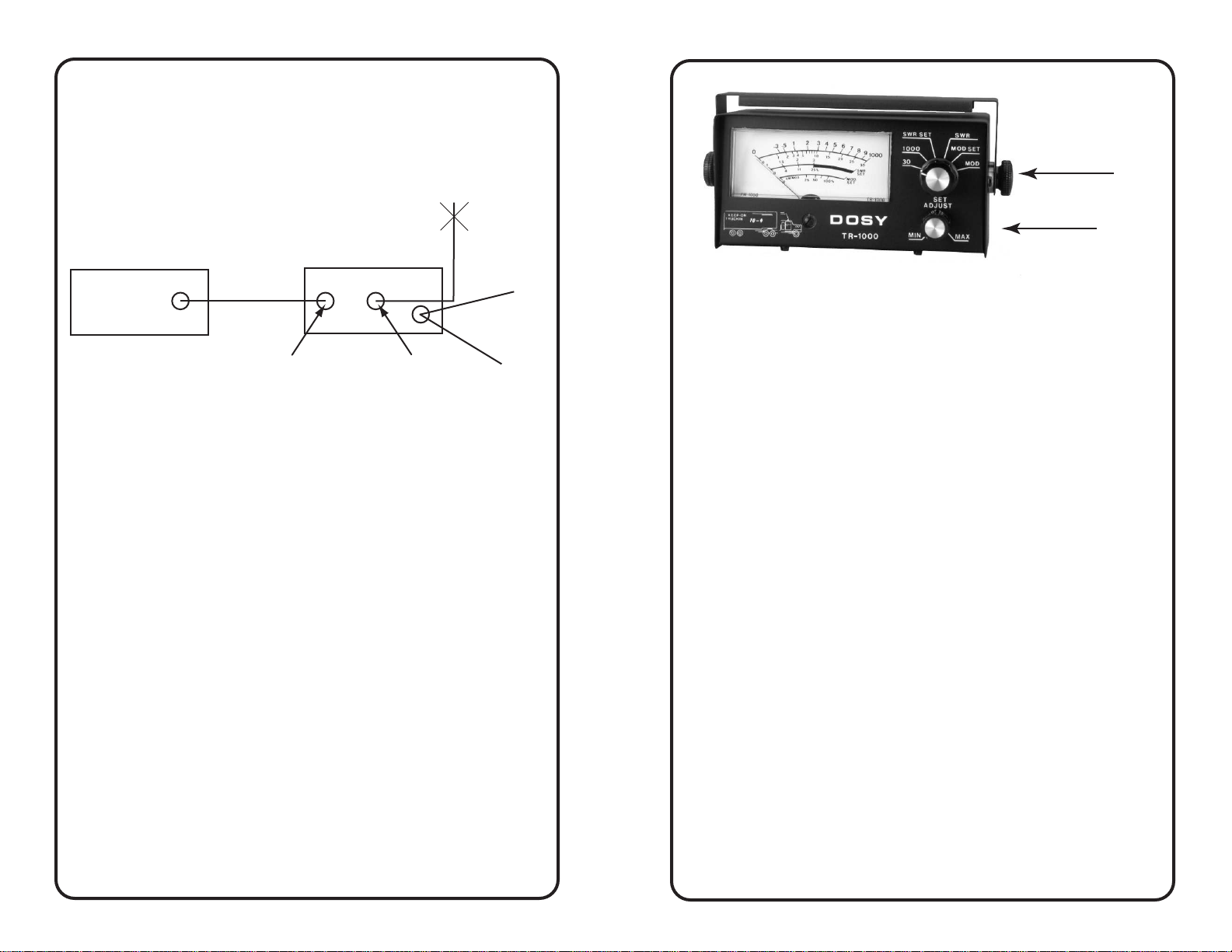
RG/58BU
Input Antenna
Red -
Dash Lts.
Black -
Ground
Jumper
Figure 1
1. Mode Selector
Switch
2. RF Level
Figure 2
Operation
WATTS
The TR-1000 Watt Meter will indicate the power output (in
watts) of your equipment at the point in the transmission line
where you have installed the Watt Meter. To measure any
power from 0 to 1000 watts on two ranges (when measuring
any unknown power) always use a higher range to start with.
Peak WATTS
The TR-1000 Watt Meter will indicate peak watts at all times
when transmitter is modulated.
SWR Check
1. Turn Selector Switch (#1 Fig. 2) to SWR/SET position.
2. Turn RF level control (#2 Fig. 2) to MIN position.
3. Key transmitter and turn RF level control to give a full scale
meter reading or to the SWR/SET on meter scale
4. With microphone keyed, switch Selector Switch (#1 Fig 2)
to the SWR position and read SWR percentage directly on
SWR scale.
Installation
NOTE: After completing the installation of the DOSY TR-1000
Watt Meter, read and familiarize yourself with the operation
section before operating the Watt Meter.
GENERAL: The TR-1000 can be mounted on top of, or below
the dashboard of either a car or truck.
STEP 1: After determining the desired location of the watt
meter, remove the two thumb nuts on both sides of the
mounting bracket and remove the mounting bracket from the
meter case. Now, position the mounting bracket and mark
where the holes are to be drilled. Drill holes using a 1/8" drill
bit and attach the mounting bracket using two 3/16" X 1/2"
sheet metal screws.
STEP 2: Note the TR-1000 can be illuminated for night use.
Locate one of the dash light wires and connect the red wire
from the watt meter to it. Attach the black wire to any ground
in the vehicle. Make sure there are no bare wires at this
point which could cause a short. If your dash lights use a
dimmer switch, the watt meter lights will dim with them.
STEP 3: Remove the antenna cable from the CB Radio and
connect it to the ANT connector on the watt meter. Using a
jumper cable made to proper length using PL-259 screw-on
connectors at each end, connect one end to the CB Radio
and the other end to the watt meter INPUT socket.