MR CARTOOL V310 User manual

Fuel Injector Cleaner & Tester
V310

Fuel injector diagnostic and cleaning
equipment is a mechatronics product
that combines ultrasonic cleaning
technology and microcomputer oil
pressure closed-loop control clean-
ing and detection technology. This
product simulates various operating
conditions of the engine, and cleans
and inspects the fuel injectors of
various automobiles and motorcy-
cles. This equipment is the neces�
sary and preferred equipment for the
automobile and motorcycle repair
and maintenance industry, research
and teaching and training depart-
ments.
Ultrasonic cleaning: Ultrasonic
cleaning can be performed on
single or multiple injectors at the
same time, which can remove the
attachments and internal blockages
on the injectors.
Uniformity detection: to detect the
uniformity of the injection volume of
each injector.
Atomization observation: Using the
background light, you can observe
the spray atomization situation of the
nozzle in a comprehensive and
careful manner.
Tightness test: It can detect the
tightness and dripping of the fuel
injector under high pressure.
Fuel injection volume detection: It
can detect the fuel injection volume
of the fuel injection nozzle under
specific working conditions (such as
the same time and the same number
of times).
All rights reserved by SHENZHEN
MRCARTOOL CO., LTD. No part of
this publication may be reproduced,
stored in a retrieval system, or transmit-
ted in any form by any means, recording,
mechanical, electronic, photocopy-
ing or otherwise, without the prior
written permission of MRCARTOOL.
The information contained herein is
designed only for the use of this unit.
MRCARTOOL is not responsible for
any use of this information as applied
to other units.
Copyright Information
Overview
1.1 Functions And Features
Main Functions
Using ultrasonic powerful cleaning
technology, strong cleaning ability.
Using electronic pressure regulat-
ing control technology, stable oil
pressure and wide adjustable
range.
Use high-quality oil pump to ensure
long-term stable use.
The use of high-definition digital
tube display makes the operation
clear and easy to learn.
The oil tank liquid level is displayed
visually, and the detection liquid
can be recycled.
Main Features

Power Supply
AC 110/220V±10%
Frequency
50HZ±0.5
Relative Humidity
<85%
Environment Temperature
0℃~+40℃
External Magnetic Field Strength
<400A/m
No Open Flames Are Allowed
Around
Structure And Composition
2.1 Structure
1.2 Working Environment And
Technical Parameters
Bright background light, you can
clearly see the various situations of
the fuel injector when it is working.
It has replaceable composite joints
suitable for a variety of vehicle
types.
Within the allowable adjustment
range, the test time, working
frequency, fuel injection times,
shortest switching period, etc. of
the fuel injector can be adjusted
arbitrarily.
Working Environment
Tank Capacity
2000 ml
Range Of Rotation
0-7500 r/min
PWM Pulse Width
0~20.0 ms step 0.1ms
Time
0~10 min
Cleaning Frequency
40 kHz
Cylinder Volume
180 ml
Injection Times
0~9900 times, step 100ms
System Pressure
0~0.6 Mpa
Ultrasonic Cleaning Power
70 W
Package Dimensions
340*295*360 mm
Technical Parameters
①
②
③
④
⑤
⑥
⑦
⑧
⑨
⑪
⑫
⑬
⑩

Lock pole;1
Lock nut;
2
Top oil inlet connector;
4
Glass measuring cylinder;
5
Oil drain handle;
6
Operation panel;
7
Pressure gauge;
8
Oil outlet pipe;
9
Ultrasonic cleaning tank;
10
Signal wire;
11
Power switch;
12
Power socket;
13
Cleaning agent drain valve;
14
Testing agent liquid level
15
Oil rail;
3
3
2.2 Operation Panel Diagram
⑭
⑮
TFT color screen;
1
Function buttons;
2
Pressure adjustment;
4
Voltage selection of injectors;
3
① ② ③ ④
Ultrasonic cleaning is to use the
penetrating and cavitation shock
waves generated when ultrasonic
waves propagate in the medium, and
powerfully clean objects with complex
shapes, cavities and pores to
completely remove stubborn carbon
deposits on the fuel injector.
Operation Process
3.1 Ultrasonic Cleaning
Remove the fuel injector from the
vehicle and check whether its rubber
seal is damaged. If it is damaged, it
should be replaced in time before the
cleaning test to avoid leakage during
the test. Then put the fuel injection
nozzle into the cleaning agent,
carefully remove the external grease
and wipe it with a soft cloth.
Preparation

4
During the cleaning process, you can
hear the intermittent (approximately
5 seconds) vibrating sound when you
take the fuel injector out and put it to
your ear, so you can judge whether
the fuel injector is working normally.
Ultrasonic cleaning is strictly
prohibited when there is no cleaning
agent in the ultrasonic tank to avoid
equipment damage.
Only the ultrasonic cleaning agent
dedicated to cleaning the fuel
injection nozzle can be added to the
ultrasonic tank, and other reagents
cannot be used instead,
otherwise any malfunctions and
damages caused will not be covered
by the warranty.
NOTICE:
This function is to detect the atomiza-
tion, dripping, blockage, fuel injection
angle status of the fuel injectors and
the size and balance of the fuel
injection of each fuel injector at
different speeds.
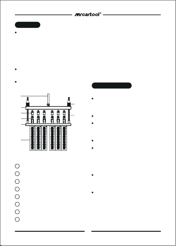
3.2 Injector Diagnostic
Add an appropriate amount of
cleaning agent to the ultrasonic
tank and spread the cleaning agent
over the bottom of the cleaning
stand.
Insert the plugs of the drive wires
into the injector sockets in turn.
(Special fuel injectors need to be
connected with an adapter cable)
Press the item selection up and
down keys to select the “01
ultrasonic cleaning" item, and then
press the working time up and
down keys to set the time. (The
system defaults to 10 minutes, if
you need to modify the time, you
can use the up and down keys to
change)
Press the start button and turn on
the ultrasonic cleaning switch on
the side of the device to start
cleaning. When working, you can
press the pause button to suspend
work or press the stop button to
exit.
During the cleaning process, the
heating switch on the side of the
equipment can be turned on to
improve the cleaning effect.
The working time gradually decreas-
es. When it is 0, the system automat-
ically stops.
Take out the fuel injection nozzle
from the ultrasonic tank, wipe the
cleaning liquid on it with a soft cloth,
and prepare for the next job.
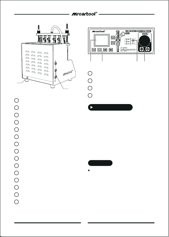
Methods And Steps
Turn on the power and turn on the
power switch on the side of the
main unit.
Put the cleaning bracket in the
accessories into the ultrasonic
cleaning tank, and place the wiped
fuel injector in the cleaning bracket
positioning hole of the ultrasonic
tank.

Oil outlet pipe;
1
Oil rail;
2
Injectors;
4
Upper plate seat;
5
Glass measuring cylinder;
6
Lock nut;
7
Lock pole
8
Top oil inlet connector;
3
Confirm that the injector to be tested
has been installed properly and the
signal wire has been plugged in.
Select "02 Idle Speed Test".
Press the working time up and down
keys to set the time. (Generally set to
2 minutes)
Press the start button to start work.
Turn the pressure adjustment knob to
adjust the pressure to 0.25~ 0.3 MPa.
(In the electronic injection system, the
general oil pressure works at
0.25-0.3MPa)
Press the up and down keys to select
the appropriate pulse width. (The
system default is 3ms).
The working time gradually decreas-
es. When it is 0, the system automat-
ically stops.
02 Idle Speed Test
Confirm that the oil drain handle is
open, use the funnel in the
accessories to add the test liquid to
the equipment through the glass
window, and pay attention to
control the flow rate during the
addition to avoid overflow.
Add 1 bottle (about 1000ml) of
testing agent each time.
Install the fuel injector.
Preparation
Methods And Steps
5
(1)Select the top oil inlet connector
from the accessories and install it into
the oil separator.
(2)Install the fuel injector in the
forward direction (apply a little grease
on the “O" ring of the fuel injector)
(3)Put the horizontal end of the oil
separator and the fuel injector on the
upper plate seat, and tighten the two
ends with the locking rod. Ready to
test.
Top-in Fuel Injector Installation Diagram
①
②
③
④
⑤
⑥
⑦
⑧

Select "03 Medium Speed Test".
Press the start button.
The rest of the operation steps are
consistent with item 02.
03 Medium Speed Test
Select "04 High Speed Test".
Press the start button.
The rest of the operation steps are
consistent with item 02.
04 High Speed Test
The fuel pressure, working time and
pulse width are automatically set by
the system. The time system
defaults to 10s as a cycle period,
and the user does not need to set it
separately.
The system will automatically and
continuously cycle three times to
simulate the working condition and
fuel injection volume of the fuel
injector when the engine is
accelerating uniformly at 750 to
7500 rpm.
NOTICE:
The pulse width system defaults to
3ms, no need to set it again.
Whether the fuel injection nozzle is
dripping and leaking when the
simulated oil pressure is 0.3Mpa.
NOTICE:
6
Select “05 Accelerating Test”.
Press the start button.
05 Accelerating Test
The fuel pressure, working time and
pulse width are automatically set by
the system. The time system
defaults to a cycle of 10s, and the
user does not need to set it
separately.
The system will automatically and
continuously cycle three times to
simulate the working condition and
fuel injection volume of the fuel
injector when the engine is idling
(750 rpm), medium speed (4500
rpm), and high speed (7500 rpm).
NOTICE:
Select “06 Variable Speed Test”.
Press the start button.
06 Variable Speed Test
Select "07 Leak Test".
Press the working time up and
down buttons to set the time.
(Generally set to1minute)
The rest of the operation steps are
consistent with item 02.
07 Leakage Test
Select "08 Idle Spray Volume".
Press the up and down buttons to
set the number of times. (Generally
set to 2000 times)
Press down on the oil drain handle
to observe the fuel injection
volume.
Press the start button to start the
test.
08 Idle Speed Spray Volume Test

Simulate the working conditions
and fuel injection volume of the
engine when the fuel injection
nozzle works for a certain number
of times when the engine is idling.
DESCRIPTION::
Storage And Maintenance
4.1 Storage
7
Flow balance Test the flow balance
at different speeds. When the liquid
level in the measuring cylinder is
2/3 of the measuring cylinder,
pause or stop work to observe the
balance of the fuel injection
volume. The deviation of the fuel
injection volume of all fuel injection
nozzles on a vehicle should not
exceed 2%. Or refer to the relevant
technical manual of the fuel
injector to judge the flow balance
of the fuel injector.
Observation of fuel injection shape
Observe whether the fuel injection
shapes and angles of all fuel
injection nozzles on the same car
are uniform at various speeds. At the
same time, you can adjust the
opening pulse width of the fuel
injection nozzle to check whether the
minimum opening pulse width of the
fuel injection nozzle is consistent.
Leak detection test Leak detection
test is to detect the tightness of the
injector needle valve under the high
pressure of the system. (Observe the
tightness of the fuel injector,
generally there should be no leakage
within one minute)
NOTICE:
Select “10 High Spray Volume”.
The rest of the operation steps are
consistent with item 08.
10 High Speed Spray Volume Test
After the test, raise the drain
handle and put the testing agent
back into the tank.
Select “09 Medium Spray Volume”.
The rest of the operation steps are
consistent with item 08.
09 Medium Speed Spray Volume Test
Display the product number and date
of manufacture of the device.
Turn off the power and unplug the
power plug.
Put all connectors back into the
accessory box for storage.
Drain the ultrasonic cleaning agent.
Wipe the equipment clean with a dry
soft cloth.
If the machine needs to be stored for
a long time, discharge the testing
agent into a bottle and seal it.
4.2 Maintenance
Replacement of testing agent After
the testing agent has been used for a
period of time, a lot of impurities will
11 Unit Info

Since the test device is part of quartz
glass, it is easy to break, so do not
place other objects around the
equipment to avoid bumping and
breaking.
Precautions
8
If there is no digital display after
power on, please check whether
the power supply is powered; if so,
check whether the plug is connect-
ed firmly, or whether the fuse is
blown. If it is not broken, and the
switch is still invalid after pressing
the switch several times intermit-
tently, please contact the manu-
facturer and must not disassemble
it by yourself, otherwise our com-
pany will not provide warranty.
When no cleaning agent is added to
the ultrasonic tank, it is strictly
prohibited to open the ultrasonic
cleaning item to avoid damage to
the ultrasonic system.
Every time the test solution is
changed, it must be cleaned up,
and then 1L of new test solution
should be added.
The use of unqualified testing
agent will cause corrosion of the oil
pump, oil supply pipeline and failure
of the pressure gauge.
Using other cleaning agent and
testing agent will cause the
equipment surface coating to peel
off.
It is strictly forbidden to use
kerosene, gasoline or other testing
agent and cleaning agents as
testing agent and cleaning agents
for this machine. Otherwise, the
“O" ring and pipeline rubber parts
in the equipment will be damaged,
causing leakage.
The cleaning agent and testing
agent should not be mixed up.
will accumulate, and the agent
containing dirt cannot be used,
otherwise it will easily block the fuel
injector. When replacing the agent,
first open the testing agent drain
valve to empty the tank, and then
inject a little testing agent to clean
the interior of the tank. After
cleaning, drain the fuel tank again
and then pour 1L of new testing
agent into the tank.
Fuse replacement there is a square
box marked with a fuse on the
power socket on the left side of the
device, and the fuse can be seen by
opening the box. If it is blown,
replace it with a new one.

9
This manual introduces the product
in detail to the functional features,
working parameters, structure, opera-
tion methods and principles. The
company reserves the right to change
the product design and specifica-
tions. the physical configuration shall
prevail on the content of the product
packaging.
Special Note
Repair or replace the equipment will
be done according to the specific
fault conditions.
We guarantee that all replacement
parts, accessories or equipment are
brand new.
When there is a product breakdown
that can not be solved within 90
days, customer should provide video
and pictures as proof, we will bear
the freight cost and provide custom-
er the accessories in need to replace.
After receiving the product for more
than 90 days, the customer shall
bear the freight cost, we will provide
the accessory for free to replace.
There are 2 years’ warranty for MRCAR-
TOOL product main unit and 1 year
warranty for the accessories since the
day the customers have received the
product parcel.
Warranty Service
Warranty Access
Items that come through the unoff
icial MRCARTOOL purchase channel.
Product failure is caused by incorrect
use of the product, use for other
wrong purpose or human factors.
Not Covered Warranty

Table of contents
Other MR CARTOOL Test Equipment manuals