WARRANTY
The 376/379 Electron Beam Source Crucible Indexer is guaranteed against faulty
materials, function, and workmanship for a period of 12 months after delivery from
Telemark. Components which are purchased by Telemark from other
manufacturers will be guaranteed for any lesser time that such manufacturer
warrants its product to Telemark. This warranty is valid only for normal use
where regular maintenance is performed as instructed. This warranty shall not
apply if repair has been performed or an alteration made by anyone other than an
authorized Telemark representative or if a malfunction occurs through abuse,
misuse, negligence, or accident. No charge will be made for repairs made under
warranty at Telemark’s facilities. Freight costs both ways will be at customer’s
expense. Telemark reserves the right for final warranty adjustment.
USER RESPONSIBILITY
The user is responsible for proper operation and ordinary maintenance of the
equipment, following procedures described in this manual, including reference
documents. Proper operation includes timely replacement of parts that are
missing, broken, or plainly worn. If the user has a reasonable doubt about
understanding the use or installation of a component, Telemark Technical
Service should be called.
It is vitally important that the user properly install the equipment as described in
Chapter 3 (Installation) of this manual. The Warranty will be void if the
equipment is improperly installed.
Alteration of the design or any function of the equipment voids the warranty and is
entirely the responsibility of the user.
SAFETY WARNING
General Precautions: Human contact with the voltages present within the power
supply and vacuum system can be fatal. Make sure that the input power is turned
off before opening the doors or removing panels. Short all HV feedthru
connections with a grounding hook before accessing the indexer main body.
ii
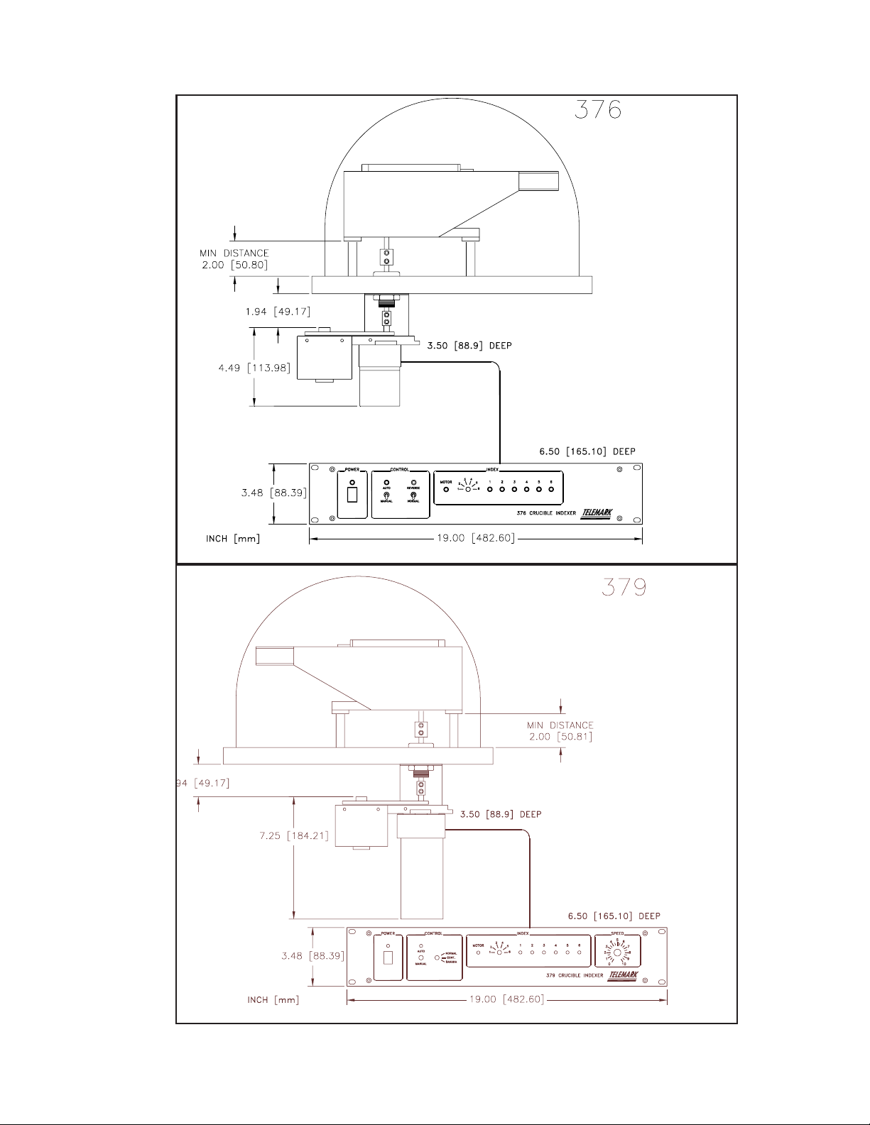
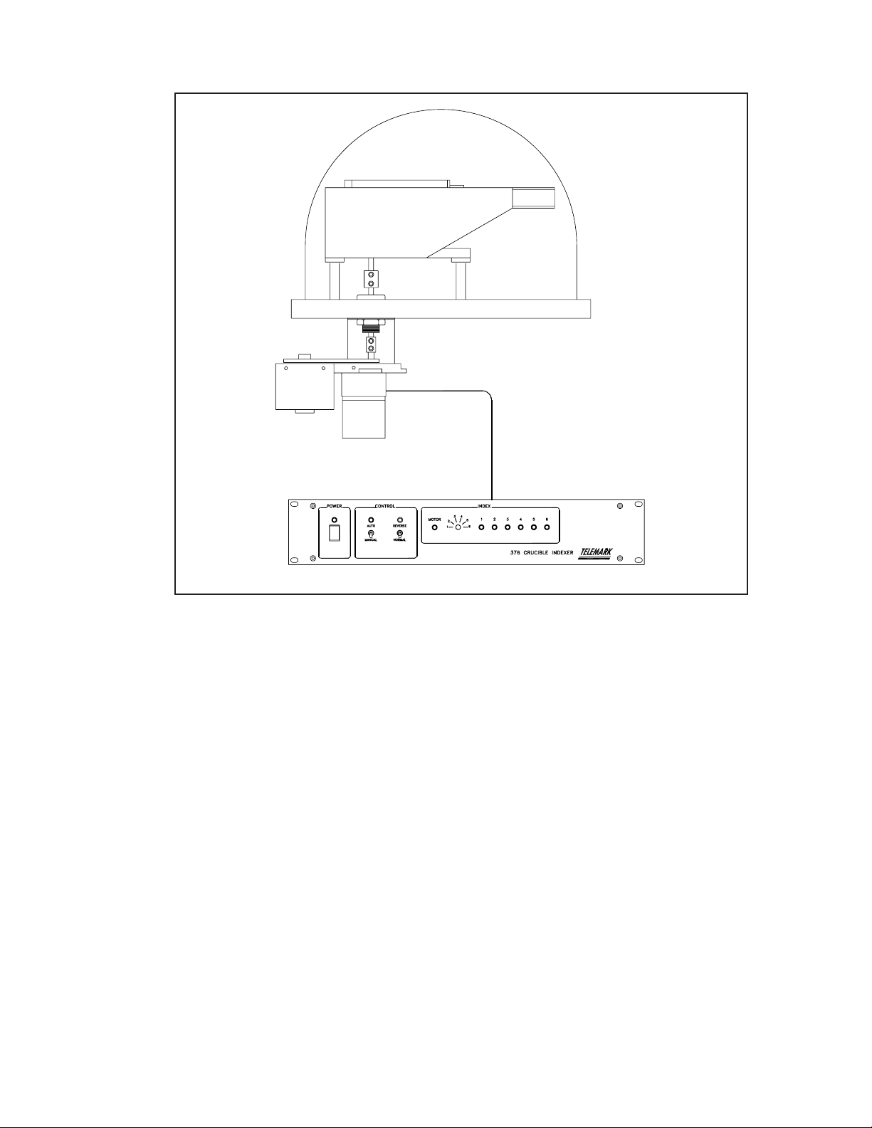
Telemark 376/379 Crucible Indexer