Mr.Ken LA NEW ABS 56" User manual
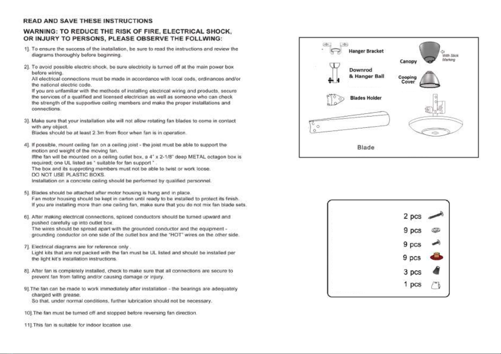
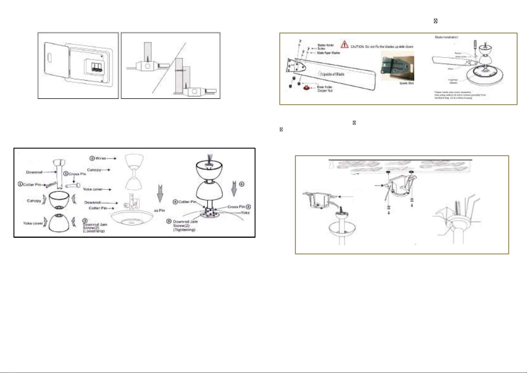
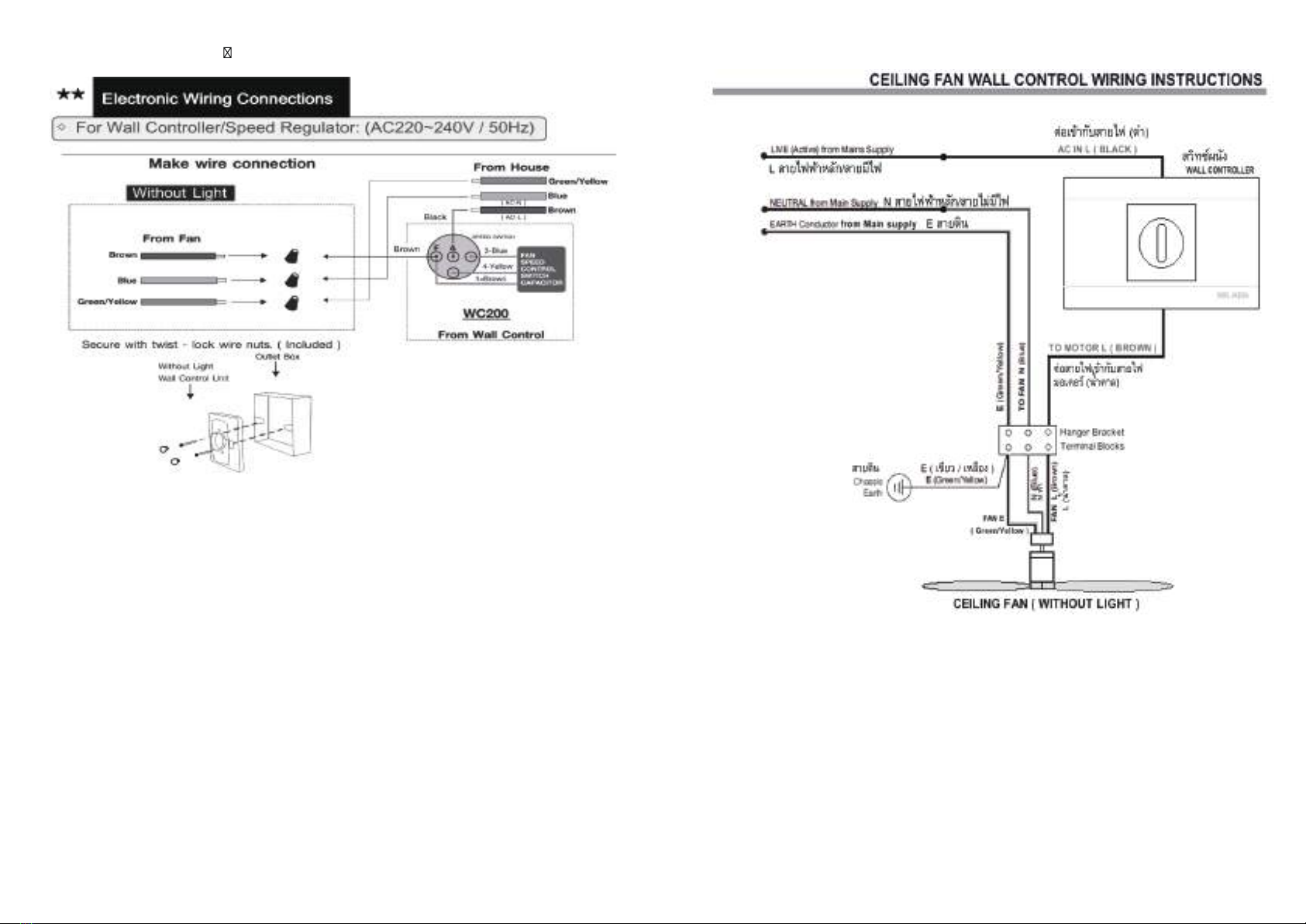
ัิ
์ู
์ู ู ้
์ู

1
Unpack and inspect fan carefully to be certains all are included.
Hardware Bag
Motor complete set
Hanger Bracket Wood Screw
Screw Paper Washer
Blade Holder Screw
Coopper Nut
Wire nut
Blade Balance Kit
2

Assembly and installation steps for fans.
Downrod & Yoke & Canopy Installaon
1. Turn off power at breaker box to avoid possible electrical shock.
2. Use metal outlet box suitable for fan support. Secure outlet box directly to the building structure
using wood screws (included). Outlet box must suport 40 ibs min.
2.1. Remove cross pin and cotter pin from downrod.
2.2 Insert downrod through canopy and yoke cover, and feed motor lead wires through downrid.
2.3 Looesn 2 Dowrod jam scews at yoke. Insert dowrod assembly into yoke.
2.4 Insert the cross pin through yoke & downrod and secure with cotter pin
2.5 Tighten both downrod jam screws to furher secure downrod.
2.6 Pull down the yoke cover to cover yoke.
3
Moter & Blade Installa on
3.1
Upside the blade , Fasten Blade onto motor assembly hole using wahers & motor screws provided
from hardware bag. (Or fix in the Motor housing)
3.2. Then remove the two nuts a
ached to the motor. The propeller to the same. Put the nut back to the
ghtening.
Hanging the fan
4.
1Check whether the installation is strong enough to be installed.
4.2
Hold the base with the nut in the desired position. The position is already prepared for the cable.
4.3
. Composed of pipes and ball Insert the power cord and connect it to the motor. completed Go in to
hang Turn down the lock. After that, move the watch to make sure it is strong. If the ball is l
ocked, it can
not move.
Ceiling
Hanger
Bracket
Hanger
Bracket
Ridge
Ball Notch
4

5.Electronic Wiring Connec ons
5
20
6

Step 1 –
( Turn off the main power supply in the circuit breaker box,
before commencing the installations.)
1. Make wires connec�on according to the wiring instruction
in the rear page.
2. Remove the wall control front plate using a flat and small
screwdriver.
3. Mount the wall control unit onto wall outlet box with the
provided two screws firmly.
( Can be installed vertically or horizontally.)
4. Replace the front plate.
5. Replace the power supply; the wall control is now ready for
operation.
CAUTION:
This is NOT a 360-degree rotate switch,
must turn counterclockwise 3-2-1-0
to switch the fan off
spiTlortnoCdeepSnaF-2petS
1. In case the fan is a pull chain Set the pull chain switch.
Keep in position "High speed" if your ceiling fan
Set the speed control switch.
2. You can now turn the knob clockwise.
To control the fan speed (respectively)
Turns off 0 fans
1 - 4 Adjust the fan speed. Chasing from low speed
To the high speed
7
INSTUCTION:
V980
Installa on of Transmi er
Wall Mount Holder with two
screws.
Ceiling fan Remote Control
Wiring Connection
IMPORTANT:
Keep antenna safely inside canopy.
Make sure its wiring is not cut or damaged
FUNCTION OF TRANSMITTER
1
2
3
4
5
6
1Hr 3Hr 6Hr
The function of the transmitier
ON / OFF: Turn the fan on or off.
Speed: Press bution 1-6 to select
speed level.
Off bution: Press the shutdown bution to
deactivate the fan.
Timer button: Press button 1,3, or 6 hours
to set the auto-off time atter starting
activation.
Light on / off button: Turn on the light,
press the top of the button. Turn off the
light by pressing the botton of the
8

Problems and Troubleshooting
Problems
1. Fan does not work.
2. Noise fan
3. The fan vibrates
abnormally.
Cause
1. Connecting the power cord to the fan or connecting
the power cord to the fan control system. Not good
enough
to make the fire is not complete.
1. Fasten the screws not firmly.
2. Have a loose screw on the motor fan assembly.
1. The propeller holder is not in position.
2. Hanging fan base The ceiling is not tight.
3. Impeller weight is not balanced.
3. The fan vibrates abnormally.
Troubleshooting
1. Check the wiring harness for the fan. And the power cord
in the fan control switch firmly.
1. Install the impeller securely before using the fan.
2. Check whether all the screws tighten.
1. Make sure that the screws that hold the rotor are mounted
in place and sealed to the motor.
2.Make sure that the fan base hangs. It has a ceiling. All screws
are tightened.
3. Switch the rotor by number on each blade. Then change
the impeller in the order of the number attached.
Test the spinning fan to balance the balance.
3. The fan vibrates abnormally.
9

ัิ
์ู
์ู ู ้
์ู

1.
2. ด
3.
4. า่
แงอ้ต
5.
1 วัต
6.
ออกยแ
7.
UL
8.
9. –
10.
11.
:
อ่ตติวีชยีสเอืรห
นอืตเาํค
1

ูน
ั็ํุ
ุ
ู
หง้ัทณรกปุอาวจในแหใอ่ืพเงัวะรดัมะรงายอมลดัพบอสจวรตะลแดปเ นักยวดูยอมวรดม
ู
ุุ
ัุ็ ู
ัุ็
็
ัุ
2
Unpack and inspect fan carefully to be certains all are included.
Hardware Bag
Motor complete set
Hanger Bracket Wood Screw
Screw Paper Washer
Blade Holder Screw
Coopper Nut
Wire nut
Blade Balance Kit
าหญัป
สาเหตุ
อืรหม ์ชทิวสบักฟไยาสอ่ต
รจงวบรค่มไฟไ้หใาํทีด่มไมลดัพมุคมาวคบบะร
ง่นหแาํต
าหญัป้กแีธิว
บบะร์ชทิวสนใฟไยาสะลแมลดัพฟไยาสงอขอ่ตดุจขไ
น่นแ้หใมลดัพมุคบวค
์รอตเอมบัก
นัข้ดไูรกสา่วนาดพเา้ฝบักดคึย้ดไ
วัตกุทว้ลแน่นแดึย
9
2

INSTUCTION:
V980
Installa on of Transmi er
Wall Mount Holder with two
screws.
Ceiling fan Remote Control
Wiring Connection
IMPORTANT:
Keep antenna safely inside canopy.
Make sure its wiring is not cut or damaged
FUNCTION OF TRANSMITTER
1
2
3
4
5
6
1Hr 3Hr 6Hr
The function of the transmitier
ON / OFF: Turn the fan on or off.
Speed: Press bution 1-6 to select
speed level.
Off bution: Press the shutdown bution to
deactivate the fan.
Timer button: Press button 1,3, or 6 hours
to set the auto-off time atter starting
activation.
Light on / off button: Turn on the light,
press the top of the button. Turn off the
light by pressing the botton of the
3
8
ัํํํ
ั่ื่ั
ั่ื่ั
ัื
็ัื่ืุ็
ัิ่ืุุ
่ัืุ้ัุ
่ิัิัั้ั่ื
ุุ
ุ
1
2
3
4
5
6
1Hr 3Hr 6Hr
ั
ั็ั่ื
นาดพเมลดัพทมโีรฟไยาสอตราก
8

Step 1 –
( Turn off the main power supply in the circuit breaker box,
before commencing the installations.)
1. Make wires connec�on according to the wiring instruction
in the rear page.
2. Remove the wall control front plate using a flat and small
screwdriver.
3. Mount the wall control unit onto wall outlet box with the
provided two screws firmly.
( Can be installed vertically or horizontally.)
4. Replace the front plate.
5. Replace the power supply; the wall control is now ready for
operation.
CAUTION:
This is NOT a 360-degree rotate switch,
must turn counterclockwise 3-2-1-0
to switch the fan off
spiTlortnoCdeepSnaF-2petS
1. In case the fan is a pull chain Set the pull chain switch.
Keep in position "High speed" if your ceiling fan
Set the speed control switch.
2. You can now turn the knob clockwise.
To control the fan speed (respectively)
Turns off 0 fans
1 - 4 Adjust the fan speed. Chasing from low speed
To the high speed
 ° µ  ª
ิ
7
4
Moter & Blade Installa on
3.1
Upside the blade , Fasten Blade onto motor assembly hole using wahers & motor screws provided
from hardware bag. (Or fix in the Motor housing)
3.2. Then remove the two nuts a
ached to the motor. The propeller to the same. Put the nut back to the
ghtening.
Hanging the fan
4.
1Check whether the installation is strong enough to be installed.
4.2
Hold the base with the nut in the desired position. The position is already prepared for the cable.
4.3
. Composed of pipes and ball Insert the power cord and connect it to the motor. completed Go in to
hang Turn down the lock. After that, move the watch to make sure it is strong. If the ball is l
ocked, it can
not move.
Ceiling
Hanger
Bracket
Hanger
Bracket
Ridge
Ball Notch
ตตัว051ดุสงูสดลหโ,zH05/V042-V022CAนาดพเมลดัพบัรหาํสะามหเ(
7
4

.
3
20
5
6
ิ็ิ่ื
บัลสสแะรกาฟฟไยาจงลหแ
ีั ํั
ัิ
ีั
ิ
ั
้ํ
้ํ
ืี
ิ
5
6
Table of contents
Other Mr.Ken Fan manuals
Popular Fan manuals by other brands

ALPATEC
ALPATEC VLP 3005 VSIT user manual

dreo
dreo DR-HTF001S user manual

Modine Manufacturing
Modine Manufacturing ECO LFE Technical manual

Zehnder Rittling
Zehnder Rittling ComfoAir flat 150 Series manual

Hunter
Hunter Oceana installation manual

Omega Altise
Omega Altise OAELITEB Operation, maintenance and safety instructions