Mr.Ken MELA Instruction Manual
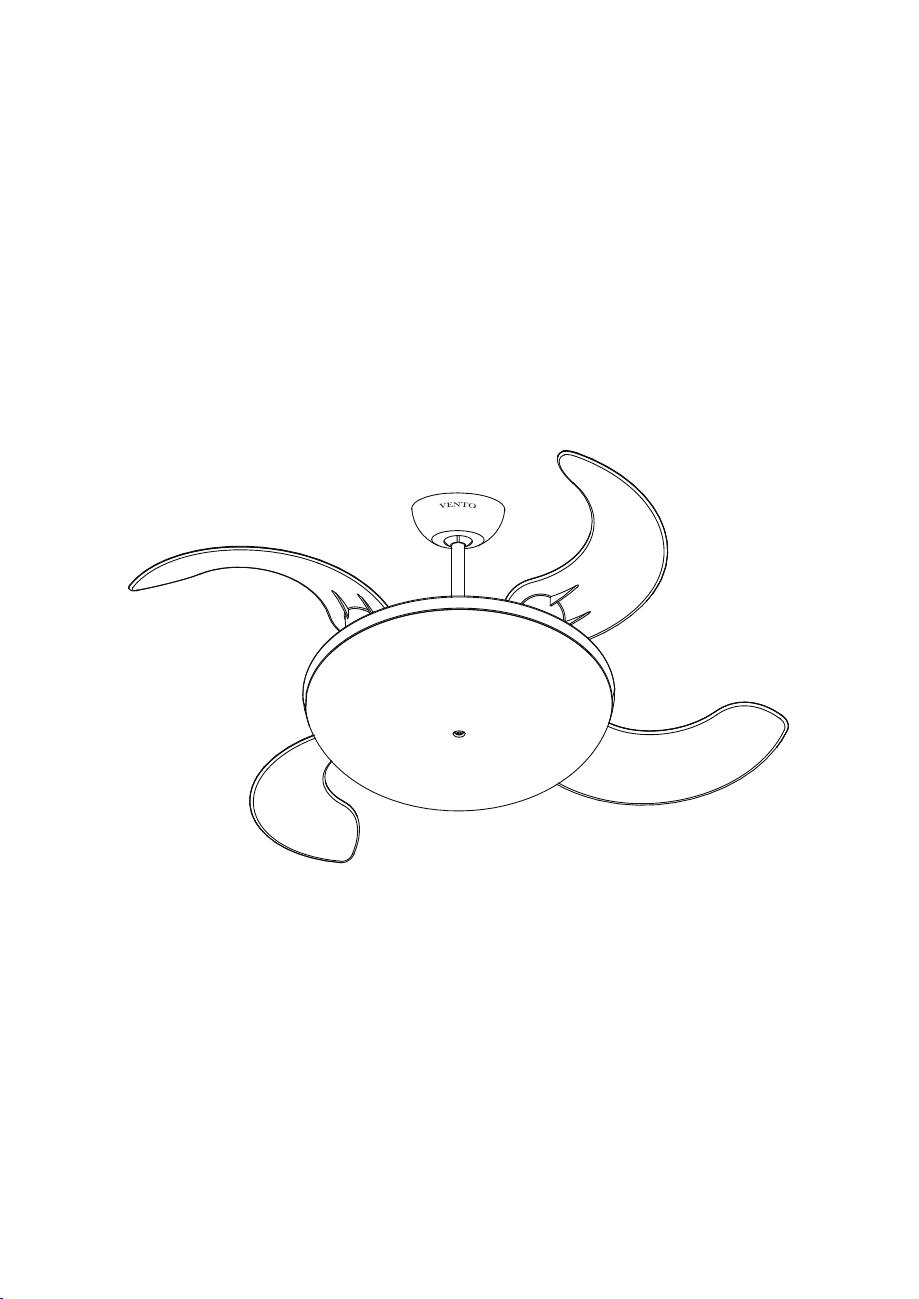
MELA
ASSEMBLY AND INSTALLATION
MANUAL OF CEILING FAN

Installation must be carried out by a qualified electrician.
Turn off the electrical mains at the circuit breaker/fuse box.
Do not use power supply other than 220V / 50Hz.
This appliance must be earthed.
When mounting the fan, ensure that the safety wire is looped across the mounting
bracket
.
The mounting
bracket
must be able to withhold a min. weight of 35 pounds.
The ceiling fan must be mounted at a min. height of 7.5 feet / 2.3m of clearance from
the floor.
Do not place any objects in the path of the blades.
When all electrical connections are done, store all wires neatly.
Make sure that all screws and connections are tightly screwed and secured.
Note
This illustrations in this manual are for explanation purposes only and may differ from the
actual unit. It is subjected to change without prior notice for further improvements.
Warning
This product is designed to use only those parts supplied with this product and/or accessories
designated specifically for using with this product. Using parts and/or accessories not designated
for using with this product could result in personal injury or property damage.
1.
2.
3.
4.
5.
6.
7.
8.
9.
10.
I. IMPORTANT SAFETY INSTRUCTIONS
A.
B.
C.
D.
E.
F. G.
a.
b.
c.
d.
f.
g.
e.
LIGHTON
LIGHTOFF
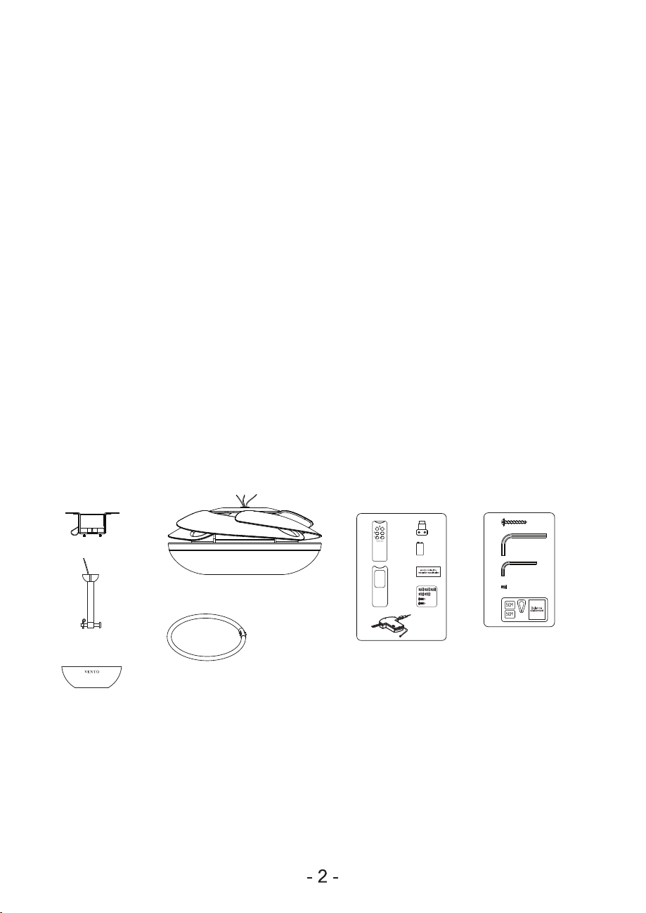
Mounting Bracket
Downrod Set
Canopy
Fan Body
T5 40W
Circular Lamp
(Optional)
.
.
.
.
.
A
B
C
D
E
.G Screw Pack
Screws For
Mounting Bracket
x2
6 mm Hex Wrench x1
4 mm Hex Wrench x1
Wire Connector x3
Balance Pack x1
h
i
j
k
l
.
.
.
.
.
.F
Remote Control
Transmitter
Transmitter Cover
Receiver
Wall bracket For Transmitter
Battery
Instruction Manual For
Remote Control
Accessories Packet
.
.
.
.
.
.
.
a
b
c
d
e
f
g
k.
l.
h.
i.
j.
2.
Check if all parts and accessories are present:
II. FOR YOUR CONVENIENCE ON ASSEMBLY & INSTALLATION,
PLEASE FOLLOW THIS MANUAL DESCRIPTION
1. Tools:
Philips Screwdriver
Slotted Screwdriver
Adjustable wrench
Cutter
Ladder
Install the power cord in accordance with the cord
.
.
.
.
.
.
A
B
C
D
E
F
NOTE: THE TRANSMITTER IS DESIGNED FOR USE WITH EITHER WALL BRACKET
FOR TRANSMITTER (d.) OR THE TRANSMITTER COVER (b.)
NOTE: PLACE THE PARTS FROM (G.) SHOWN ABOVE, IN A SMALL CONTAINER TO
PREVENT PARTS FROM GETTING LOST. IF ANY PARTS ARE MISSING, CONTACT
YOUR LOCAL RETAILER FOR REPLACEMENT BEFORE PROCEEDING.
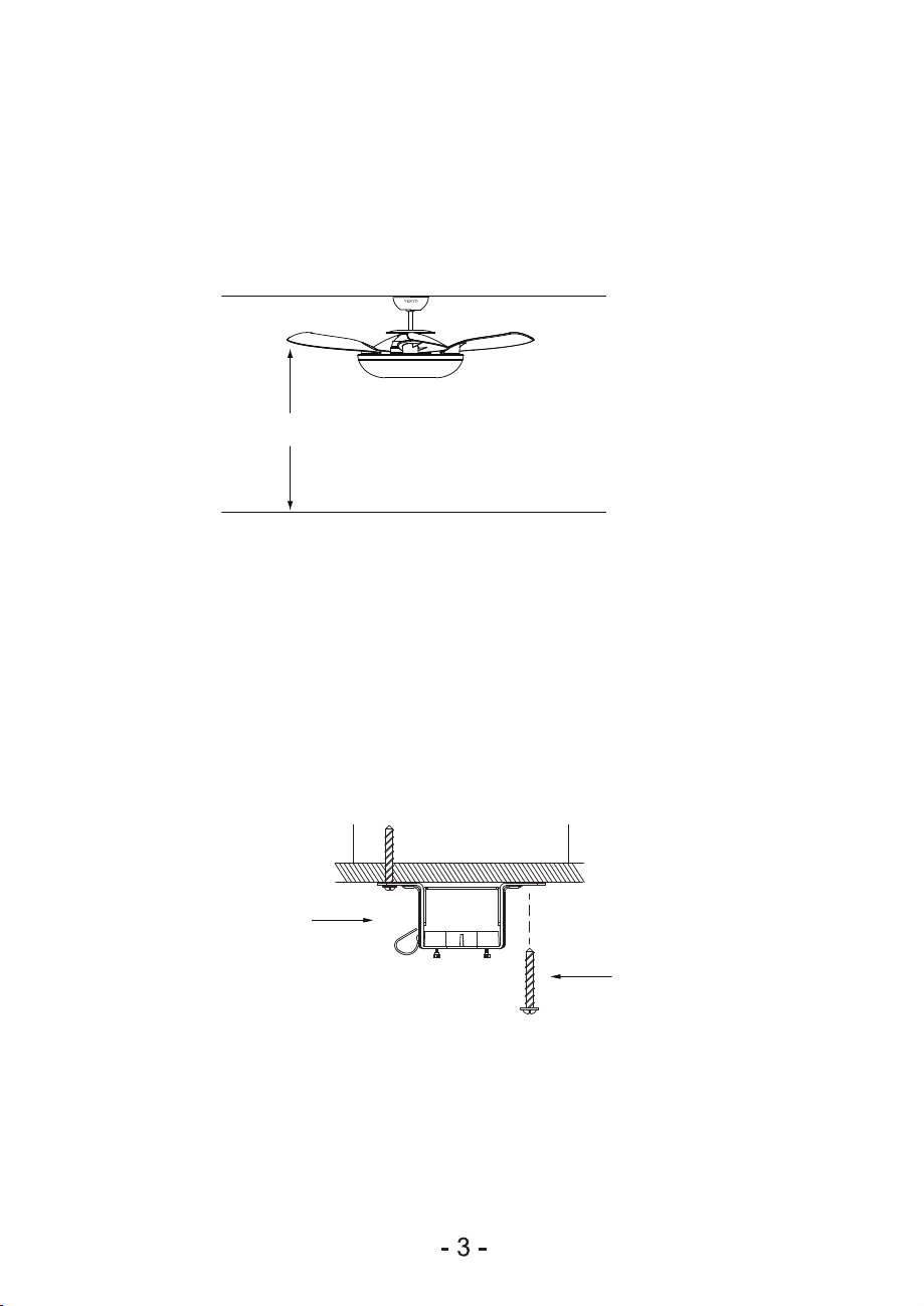
Floor
2.3m
III. INSTALLATION INSTRUCTION
1.
ATTENTION: Do not install the fan onto the partition ceiling or chapped wall.
The ceiling fan must be mounted at a min. height of 7.5ft/2.3m of clearance from the
floor.
2. The mounting bracket must be securely fastened to a structural ceiling member.
NOTE: Make sure all screws are tightened.
Mounting Bracket
Screw ( h.)

4 mm Hex Wrench
VENTO
Lock Pin
Screw
Canopy
Downrod Set
Polyester Bar
Polyester Bar
Before installation, remove two polyester bars from the fan body. Otherwise, the fan
will not function properly.
3.
- 4 -
Loosen 2 screws at the yoke of the motor assembly. Slide the canopy into the downrod.
Thread the power leads from the fan through the canopy and downrod (take extra care
not to pull power wires damage). Set downrod into yoke and rotate until the holes
match. Then, insert lock pin through the holes and firm it with R pin. Tighten 2 screws
with hexagon wrench at the top yoke of the motor assembly. Please try to shake the
downrod (ball part) and make sure 2 screws are tightened.
ATTENTION: Make sure the R pin and lock pin is proper and secure to prevent the fan
from falling or causing property damages or personal injury.
4.
R Pin
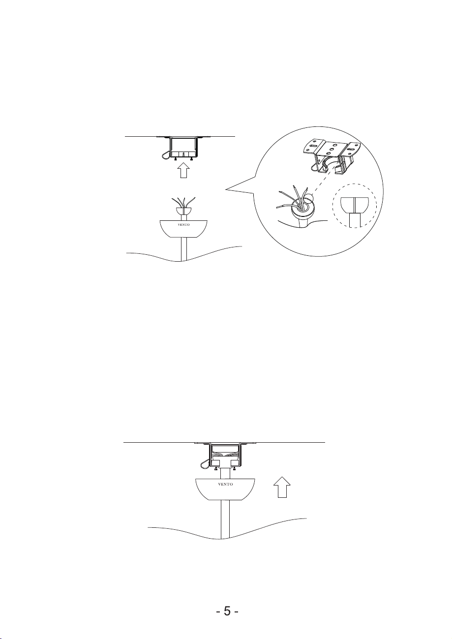
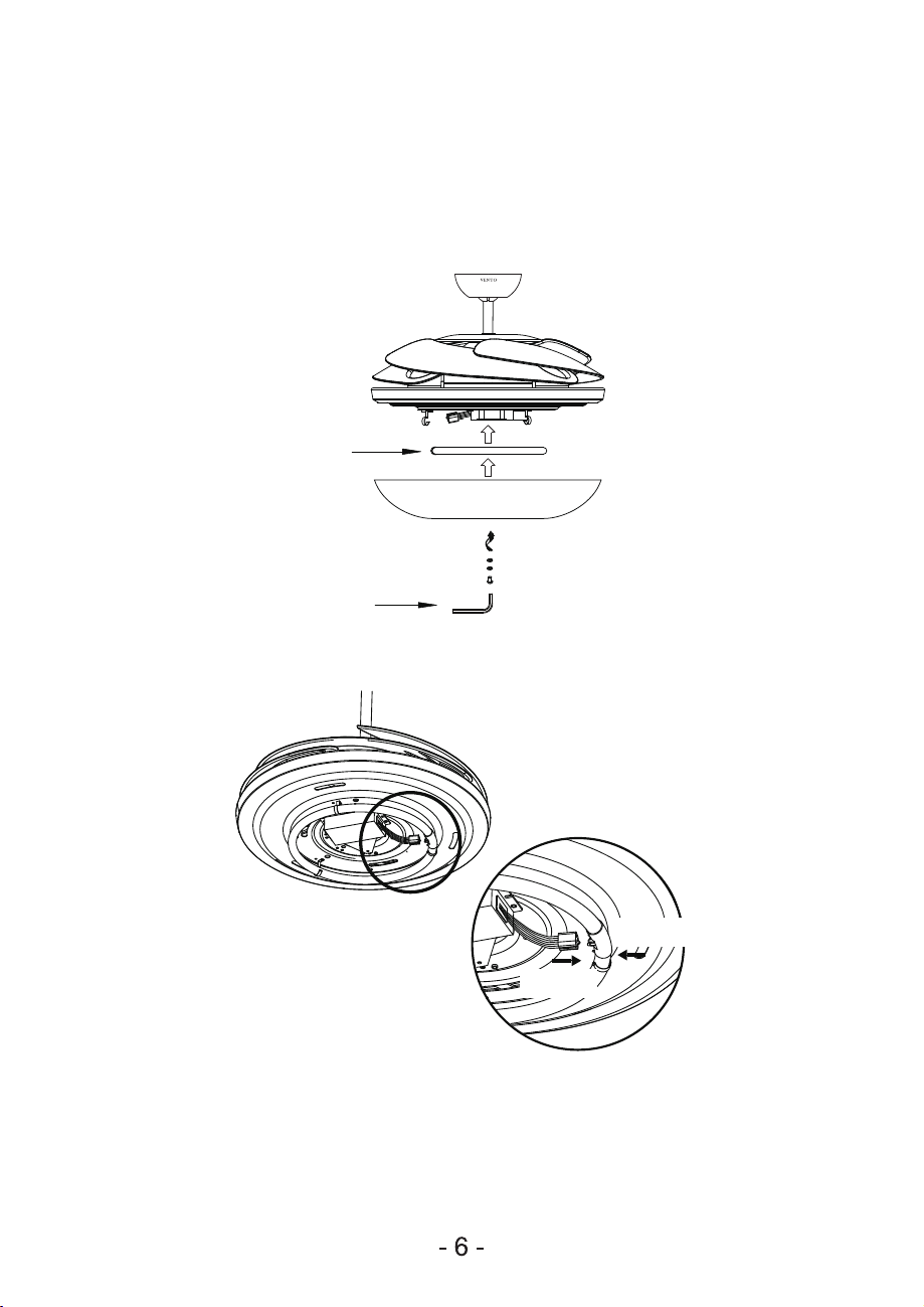
6. Insert the receiver into the mounting bracket (see the illustration on page 8-10 ). Loosen
the screws from the mounting bracket, uphold the canopy to cover the mounting bracket,
then let the mounted hole aim at the screws, then firm the screws.
ATTENTION: Make sure all wires are proper connected.
Tighten the two downrod set screws to make sure the fan run stably. Then, install
downrod (ball part) into mounting bracket opening that already securely fastened to a
structural ceiling member. The tab opposite of the mounting bracket opening should
fit in slot on ball.
5.
Push
Push
T5 Bulb
6mm Hex wrench
Plug G10Q 40W assembly chart
After locking the canopy, loosen the screw on lampshade. Install T5 circular lamp into
the spring clips, then push lamp holder into the T5 circular lamp socket. Align holes on
lampshade to the fan body. Finally tighten the washers and screw with 6mm
Hex
wrench.
NOTE: Make sure the bulb is now secure on its position against falling.
7.
IV. INSTALLATION INSTRUCTIONS FOR CEILING
FAN REMOTE CONTROL
A. IMPORTANT POINTS:
B. OPERATION INSTRUCTIONS:
C. FUNCTIONS OF TRANSMITTER:
1.
2.
3.
4.
5.
6.
7.
8.
Please read this manual and keep it for future use.
Turn off the electrical mains at the circuit breaker/fuse box.
Please note that all wiring connections should be done by a qualified electrician.
This unit is to be used in an AC220V / 50Hz supply zone only.
Do not install in damp locations or immerse in water. (For indoor use only.)
To avoid damaging the transmitter prevents dropping or banging the transmitter.
Do not attempt to shorten the receiver’s antenna wire.
If the transmitter is not used for some time, please remove batteries to avoid leakage
that will damage the transmitter.
1.
2.
After installing the receiver, make sure the transmitter has its batteries installed.
If the transmitter is not functioning properly or not function or if the fan is not moving
please do the followings:
a) Turn off the electrical mains at the circuit breaker/fuse box.
b) Follow steps on page 9-10 to reinstall the receiver.
HI
MED
LOW
OFF
LIGHT ON
LIGHT OFF
Set fan to high speed.
Set fan to medium speed.
Set fan to low speed.
Turn off the ceiling fan.
Turn on the light.
Turn off the light.
:
:
:
:
:
:
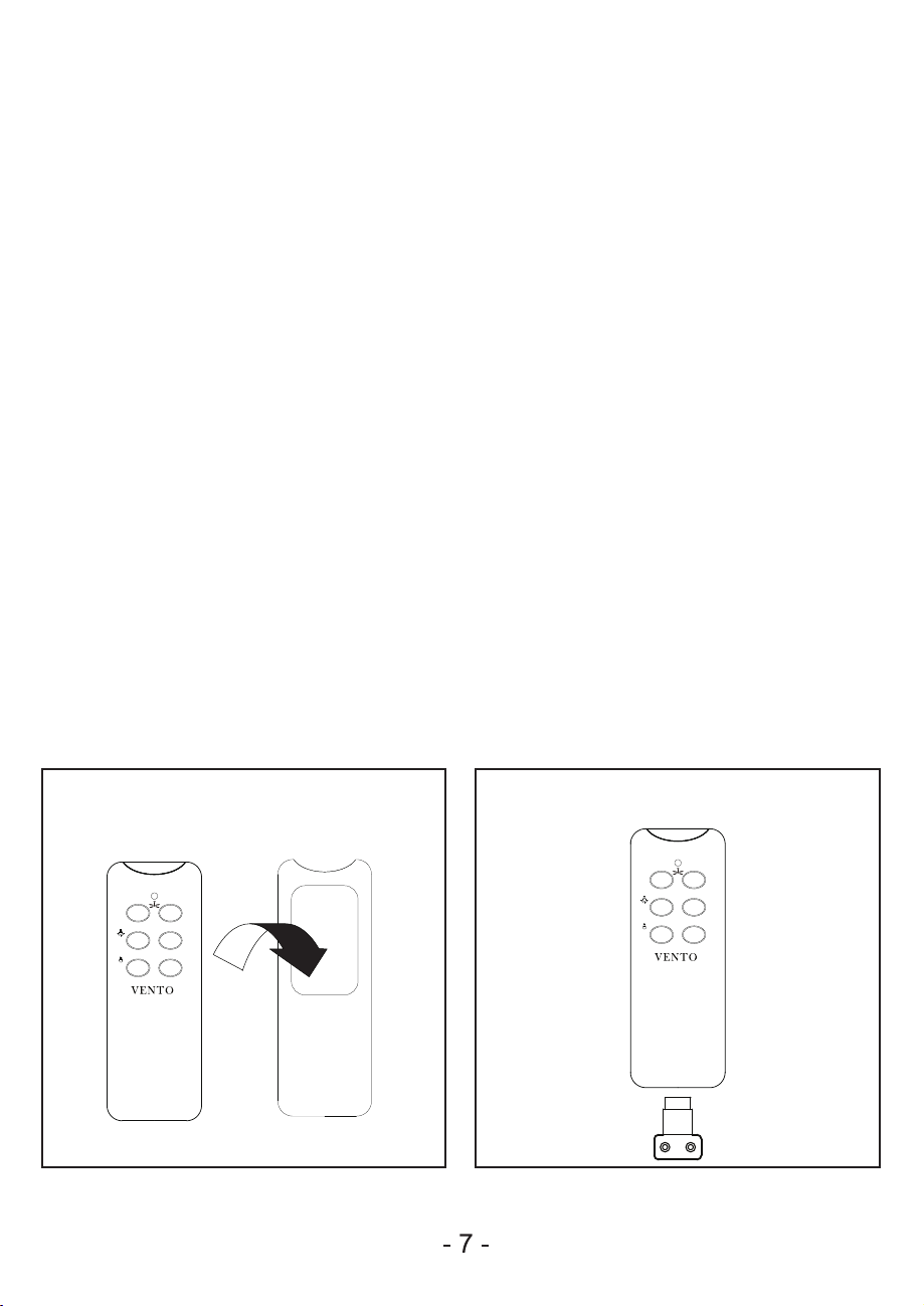
NOTE: THE TRANSMITTER IS DESIGNED FOR USE WITH EITHER WALL BRACKET
FOR TRANSMITTER (d.) OR THE TRANSMITTER COVER (b.)
LIGHT ON
LIGHT OFF
LOW
OFF HI
MED
Put the transmitter into transmitter cover. Wall bracket for transmitter
(If desired, install onto the wall with screws.)
LIGHT ON
LIGHT OFF
LOW
OFF HI
MED

V. CODE SWITCH SETTING
1.
2.
3.
4.
5.
6.
These DIP code can be pushed upward and downward to change the setting.
Both of these remote control components (receiver and transmitter) have a set of four
switches that need to have the same settings. (The total combination becomes 16
frequency codes).
The setting determines the frequency that will be used to control the ceiling fan.
Otherwise, the ceiling fan will not operate.
Once the setting has been made, slide down the back cover of transmitter to the arrow
direction. Install a 9 Volt battery.
Now the remote control receiver module is ready for installation up at the ceiling fan
of mounting bracket.
Select different combinations of dip switches to prevent mis-operation due to other
remote control fans.
RECEIVER
ANTENNA
9V BATTERY
1234
ON DIP
DIP SWITCH
Follow the arrow direction to
open the battery cover.

- 9 -
VI. WIRING FOR CEILING FAN INSTALLATION
NOTE: a.) Incorrect wire connection may damage this fan and receiver.
b.) Do not attempt to shorten the receiver’s antenna wire.
1.
2.
3.
4.
5.
A typical ceiling fan remote control is wired as shown in this wiring diagram. (Fig. 1)
Make sure that the wire of brown/blue/orange is connected.
Wires connecting the receiver and the ceiling fan have its sticker indication. The
receiver wires to the fan motor are Blue (neutral) marked TO MOTOR N and
Brown (live) marked TO MOTOR L. Orange is for the light fixture marked FOR LIGHT.
Connect wires with sticker indicating “AC IN” from the receiver-Red (live) and
White (neutral) to the wires from the ceiling.
Make sure that the ground wire from the ceiling is connected to the GREEN/YELLOW
wire of the ceiling fan.
After connecting the wires, push up the canopy till it reaches the ceiling then install
the receiver by sliding into opening in the mounting bracket. Tighten the canopy screw.
As shown in Fig.2
N / WHITE
L / RED
GROUND WIRE (GREEN/YELLOW)GROUND WIRE (GREEN/YELLOW)
N / BLUE
L / BROWN
Fig 1
CEILING FAN
AC
POWER
INPUT
N / BLUE
L / BROWN
FOR LIGHT / ORANGE
TO MOTOR N / BLUE
TO MOTOR L / BROWN
FOR LIGHT / ORANGE
ANTENNA
Fuse socket
AC POWER INPUT
WHITE (
AC IN
/ Neutral)
RED (
AC IN
/ Live)
BLACK
(ANTENNA)
BLUE (Fan / Neutral)
BROWN (Fan / Live)
ORANGE (Light / Live)
GREEN/YELLOW
(Ground Wire)
Fig 2
ANTENNA
(Do not attempt to shorten
the receiver’s antenna wire.)
CODE SWITCH
COMPLETE DIAGRAM
Completes The Chart
5A Fuse
Latch
Assemble Chart
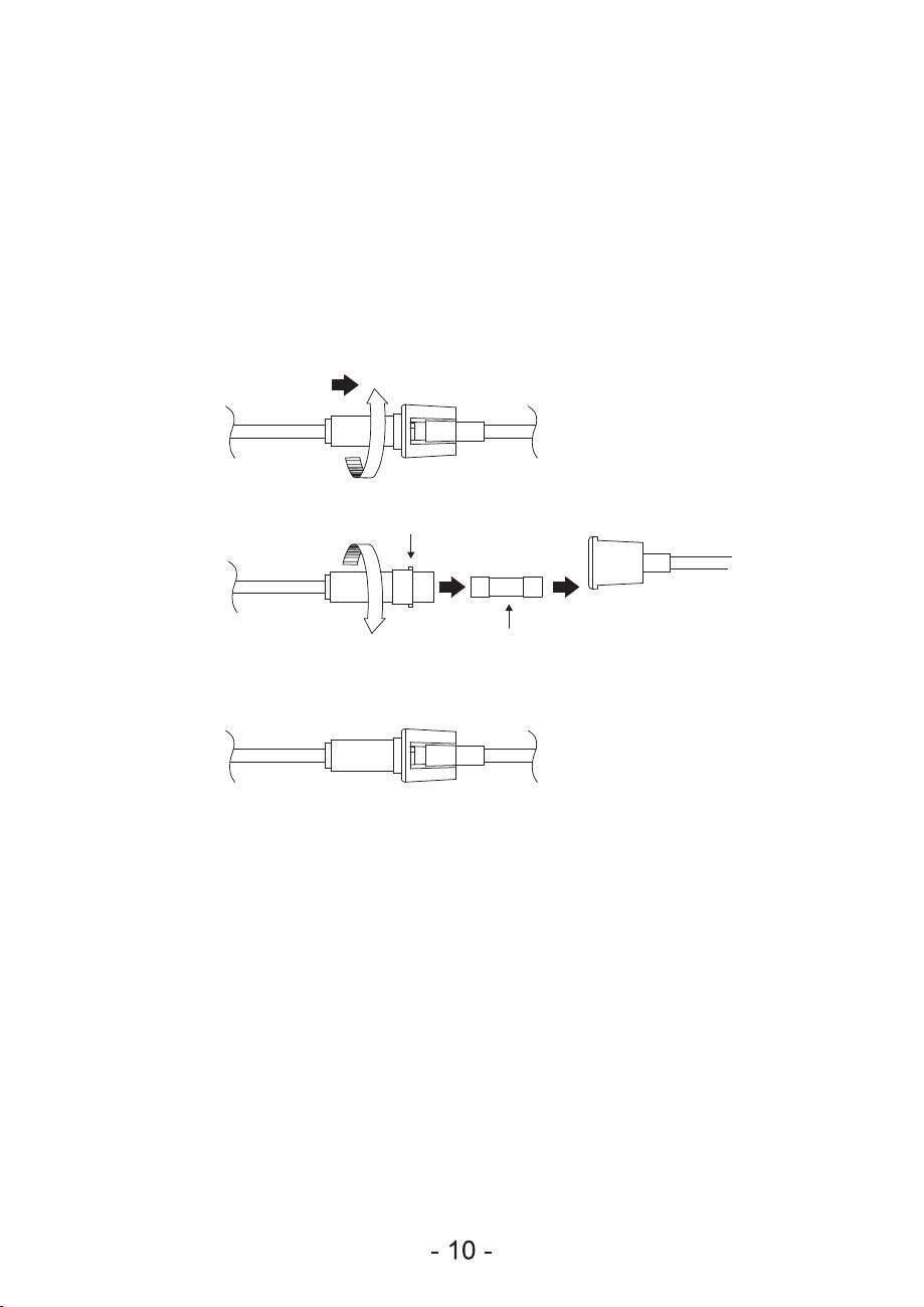
VII. FUSE REPLACEMENT
Push both side of the fuse capsule towards each other and twist it to open the fuse
capsule. Remove the damaged 5A glass fuse from the capsule then replace a new
5A glass fuse. To close the fuse capsule aline the latch and groove then push in and
twist to lock the fuse capsule.
Left Side
Left Side
Right Side
Right Side

PROBLEM A: FAN WILL NOT START
REMEDIES:
1.
2.
3.
Check fuse or circuit breaker and replace if necessary.
Turn off electrical power, check all wire connections.
Check to make sure the dip switches from the transmitter and receiver are set on the same frequency.
PROBLEM B: FAN EXCESSIVELY NOISY
REMEDIES:
1.
2.
3.
Check that all screws in fan assembly are tight and properly seated.
Check to make sure mounting bracket is installed properly.
Check to make sure light kit and glass are tight and installed properly.
PROBLEM C: FAN WOBBLES
REMEDIES:
1. Use the clip from balance pack to make sure the position. Stick the balancing weight on the
opposite side of the mark place.
VIII. TROUBLE SHOOTING

B40519B KE
Table of contents
Other Mr.Ken Fan manuals


Popular Fan manuals by other brands


NuAire
NuAire MRXBOX95-WM2 installation manual

Hunter
Hunter Hunter Ceiling fans Installation and operation manual

Bimar
Bimar VC82 Instruction booklet

Visual Comfort & Co.
Visual Comfort & Co. 5ASPR56 Series installation instructions

Enviro
Enviro HLF Installation operation & maintenance

Maico
Maico MDR EC Series Mounting and operating instructions


