Mr. Nixie IN-9 Nixielyzer User manual

IN-9 Nixielyzer Assembly Manual
Page 1
Foreword
Dear Nixie tubes friend,
Thank you for purchasing this state-of-the-art Audio Analyzer DIY kit for 6 x IN-9
Neon or Argon Bargraph tubes. You have purchased a product that captivates as a
DIY version a component quality and choice of materials that is outstanding in the
market and will certainly draw the attention as an eye catcher of your acquaintances
in the future.
However, this also means that you should not "cobble together" this kit in record
time. Take a smooth evening and about four to five hours time to build.
Also, you should already have the necessary equipment and knowledge to be able
to build such a high-quality DIY kit without complications. The resulting success will
definitely reward you for your effort and stamina.
This instructions assume electronic fundamentals, i.e. you should already know
that Electrolythic Capacitors, ICs, LEDs and Transistors are polarized components
and may not be soldered in reverse direction. These parts are also very sensitive for
electrostatic discharge. Furthermore, the usage of a temperature-controlled soldering
station with max. 1 mm wide tip and corresponding fine electronic solder as well as
appropriate tools (multimeter, TX10 and slotted screwdriver, side cutter, tweezers,
magnifying glass, etc.) are recommended.
The tubes used in this kit are made of glass, evacuated and therefore very sensitive.
The wires or the glasbulb of the tubes can therefore crack during rough handling -
even when unpacking. Complaints due to such defects cannot be accepted.
Please read and follow the steps and hints in this manual.
These are all tested and allow you a trouble-free assembly.
Important Safety Instructions
During installation, commissioning and measurements and repair special care is
required! Assembling of the circuit is at your own risk. The functionality can not be
guaranteed, nor the suitability for certain purposes. The user himself has to check
this and is responsible for this suitability.
No liability can be accepted for damages arising during or as a result of the assembly
or operation, in particular for damages resulting from a lack of electronic skills.
The Analyzer may only be operated in a touch-proof housing in dry indoor
environment. Operation without or with defective tubes is not permitted!
The person who has completed a kit or has made an assembly ready by extension
or enclosure installation, is according to VDE 0869 a manufacturer and therefore
provided to supply all documents when selling the device and also give his name
and address.
Devices which are assembled from kits themselves are to be considered as an
industrial product in terms of safety.
And now, after these necessary words - time to fire up your soldering station.
– Version 1.04 from 5th November 2019 –

IN-9 Nixielyzer Assembly Manual
Page 2
Locate the PCBs inside the components box
Crack the PCBs on the red market V-Cuts
Please print out in color page 11 and 12 of the PDF manual
with the BOM and parts locations shown on the Main Board
Let’s first assemble the two SMD parts IC2 / L1 and IC3
Get from the Semiconductor bag the SMD IC2 NCY9100, the through hole IC3
BA3830S and from the Divers bag the SMD 47µH Inductor L1.
Start with IC2 by soldering only one of the „fat“ pads in the corners. Next place the
part in position and heat the lead / pad again until the the solder melts and anchors
the part. Pay attention for the position of the IC’s notch. Now solder the three
connections in the other corners and finally the remaining 12 smaller pads. A de-
solder wick will help when you accidentally solder two pads together.
When finished, inspect your solderwork carfully with the help of a loupe !
Do it in the same way with the inductor L1. But, as this pads are very big and also
the part itself will draw a lot of heat from the soldering, you need to set your solder
iron temporarily to 400°C / 750°F for a good melting of the soldering tin. The
polarization of the inductor is negligible.
When finished, set back the temperature of the solder iron and bend very carefully
the legs of each side from IC3 until they will fit proper into the pads as this IC is
assembled without socket. Take special care for correct orientation and solder
carefully, as there’s no easy way without damaging the part or the board when you
need to swap / unsolder this part.
Main Board
Top Board #1
Top Board #2
This part is waste !
Tube mounting Top Board
Tube soldering Board

IN-9 Nixielyzer Assembly Manual
Page 3
We will build an assembling aid for the resistors and diodes
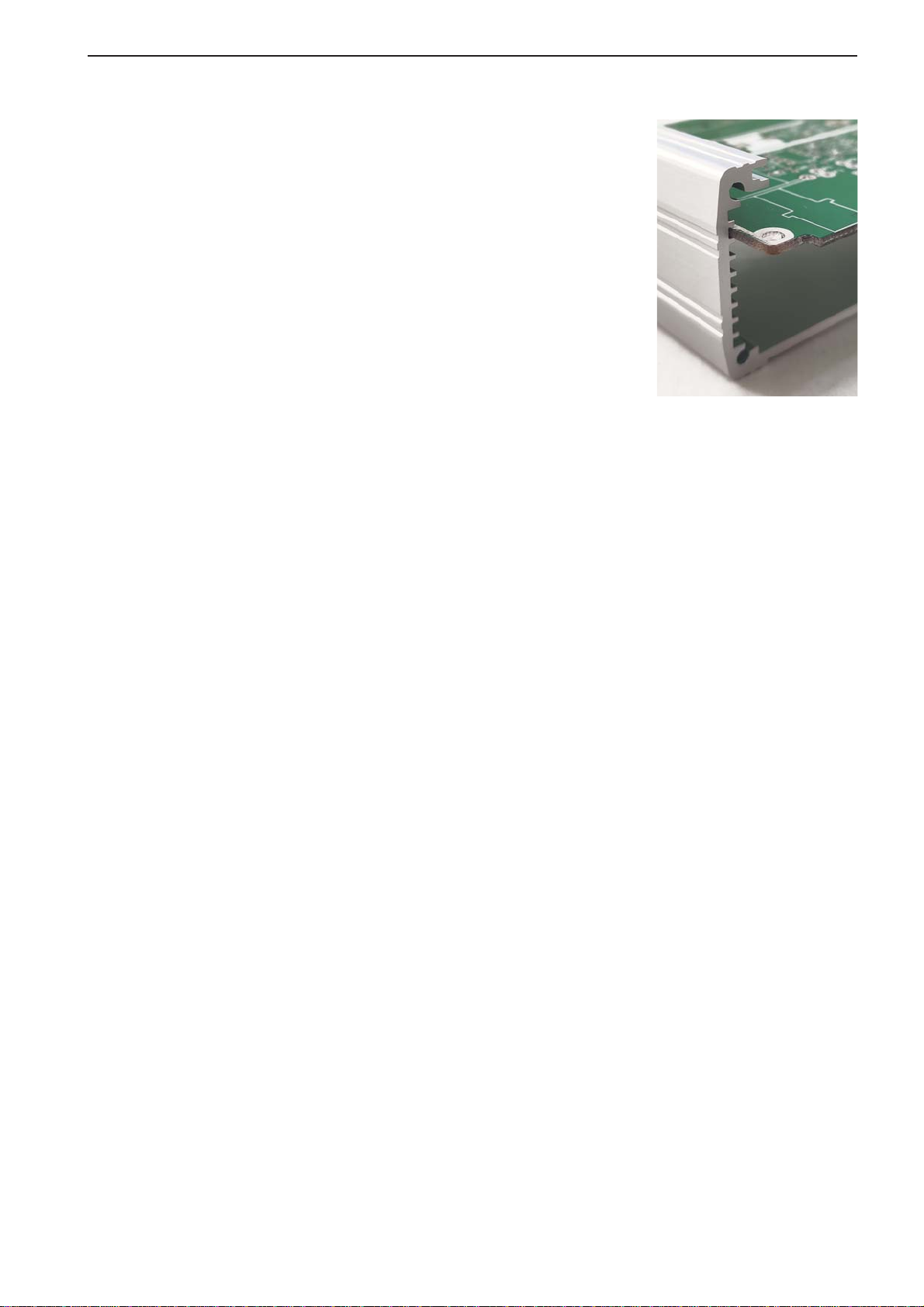
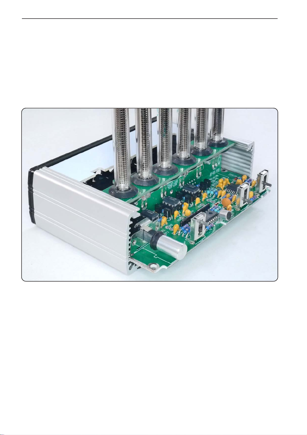
Pick up the Main Board and the aluminum frame. Slide
the PCB in the second wider upper groove as shown in the
picture. Pick up from the components box the bag with the
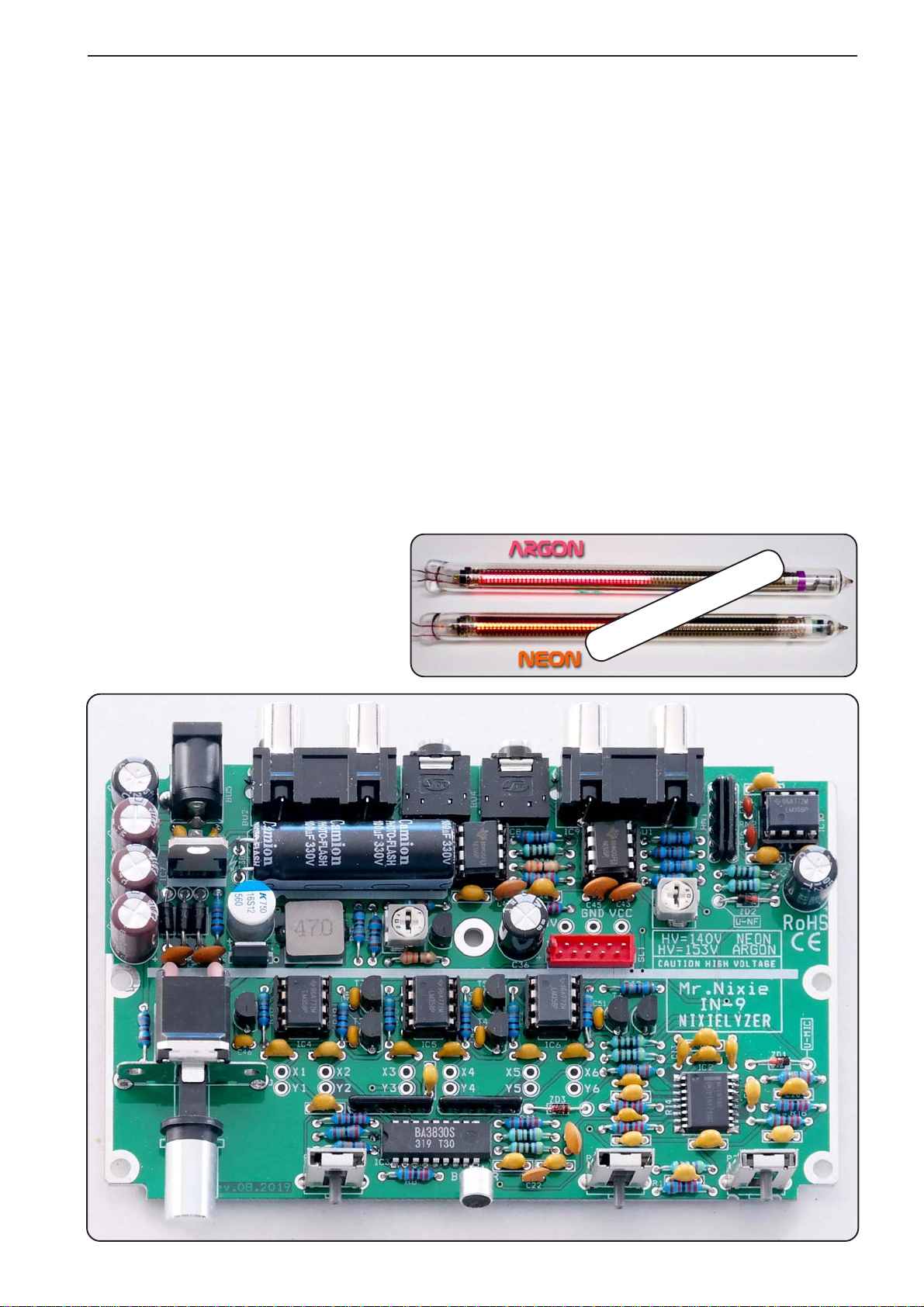
Resistors. We will now start assembling and soldering
the parts from components side. This is much faster and
easier. Start assembling and soldering the resistors value
by value, start with the lowest count = 590 kohms, followed
by 2 x 33 ohms, etc. Stop when you reach the 9 x 430 ohms
and clip all the soldered wires first on solder side. Then
continue assembling. For assembling and soldering R3 and
R16 you’ll need to pull out the board a little as they are
partially hidden by the frame on the right-hand side. Don’t
assemble the Trimmers, Potentiometes and Arrays yet.
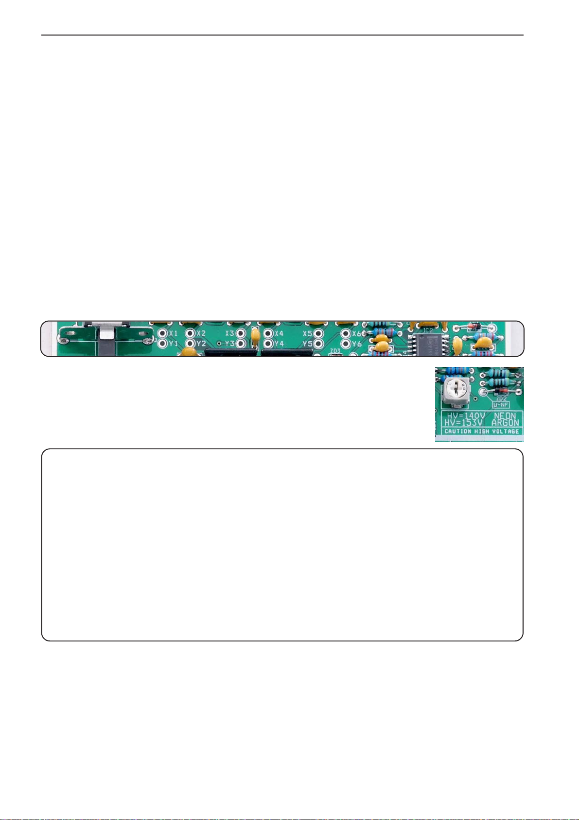
Pick up now from the Semiconductor bag only all diodes and zenerdiodes (D1...3
and ZD1...3) and assemble and solder them in the same way. Pay attention about
the correct orientation and do not mismatch ZD3 (2V7) with ZD1...2 (5V6 each).
When finished check all solderings and than clip all the wires on solder side.
Now you can put the aluminum frame on a safe place.
Assemble the four Resistor Arrays RN1...4. They have no preferred orientation,
so you can negligible the dot on the part’s silk screen.
Pick from the Capacitor bag the two 220pF C16/17 and fit them next to RN2.
On the other hand the six IC sockets from the Semiconductor bag are well
poarized, so take attention when fitting them. If you have done a mistake, try not
to unsolder the sockets. When you later fit the IC’s in the correct orientation, that
will be fine.
Also fit the two jacks BU3 and BU4 from the Divers bag. Now solder all the parts.
Pick from the Capacitor bag the six taped 1nF capacitors C46...51 and fit them.
They are located between the transistors T1...T6 and are marked with a small filled
box decale between their pads. Pick up the remaining seven taped 10nF
capacitors, fit and solder than all parts.
Flip the board now and pick LED1 from the Semiconductor bag. Bend it legs as
shown on the PCB’s silk screen. Note that the Anode is the longer wire and the
Cathode (shorter wire) is marked with an annular ring on the PCB’s silk screen. Fit
the LED and solder it from solder side. Next clip the wires on component side.
Let’s start now assembling the remaining ceramic capacitors, therefore only get the
two small bags market with 4u7 and 1u from the Capacitor bag, but keep them
in their bags for the moment!
Have first a close look on the PCB’s silk screen for the 4u7 and 1uF capacitors. They
are marked with different decales. The 1uF have only a single dash between it’s pad
whereas the 4u7 have a squared decale. Let’s start first by assembling all 1uF
capacitors, next all 4u7 capacitors. Note that there should be remain one capacitor
for each value just for spare when you have dropped one as they are hard to find by
the common suppliers. When finished, solder and clip all wires.

IN-9 Nixielyzer Assembly Manual
Page 4
Pick up from the Semiconductor back the TO92 transistors (seven taped MPSA42
in Ammo-Pack style and a BC546B), the ipac MosFet T8 – be carefully as the
MosFet is an electrostatic sensitivity device and do not fit the MosFet in wrong
direction; it’s heatsink must face away from you to the capacitor C37.
Fit from the Resistor bag the two Trimmers TR7...8 and from the Divers bag the
male Mircomatch connector SL1. Align this part correct in parallel to the PCB and
have care about the position of it’s nose.
Now solder all parts and clip the protruding wires.
Now we will fit the DC jack BU5 from the Divers bag.
Unfortuntately two different mechanical versions are used in
the kits. See the photo on right side. The jack with the „DC“
print fits fine into the PCB whereas on the other version the
rear leg is too wide and needs to be bent or clipped first. Anyway,
solder this leg for fixing the jack from component’s side first.
Next prepare the switch S1 together with the knob from the
Divers bag and the pink rubber tube from the Mechanic bag:
First cut the tube into two halves and slide them fully over the
switches’s legs. Than carefully push the aluminium coloured
knob on the stamper of S1.
Next fit from the Divers bag the two RCA jacks, from the Capacitors bag all
electrolythic capacitors except of the three 33µF 100V types and from the
Resistors bag the remaining three slider potentiometer P1...3.
When soldering all these parts do not solder the metallic mounting bezel of the
switch for an easier adjustment – if necessary – later during case assembly.
Next assemble and solder the three remaining capacitors C35, C36a...b from the
Capacitors bag and the voltage regulator IC7 from the Semiconductors bag.
Take care about the orientation. The heatsink must face to the diodes D1...3.
Prepare now the electret microphone from the Divers bag:
One pad on rear is connected via two or three small tracks to
the metallic round bezel of the microhone. This is the GND pin,
marked with „B“ on the PCB, the other wire is the signal and
market with „R“. Bend these wires as shown in the picture.
From the Divers bag pick the microphone mounting tool and slide it onto the
PCB. Next fit from top the microhone with its bent leads and solder it. The tool gives
the correct spacing from the PCB for later fitting fine into the front cover.

IN-9 Nixielyzer Assembly Manual
Page 5
Now it’s time – with ICs not fitted – to have a voltage check:
Plug in the 15VDC power supply and switch the device on. Have a first look at the
LED on the buttom. Does the LED light up?
If not, remove at once the power supply and check for the fault!
When ok, check the MosFet and the inductor, that there’s no self-generated heat.
Next do a voltage measurement on the test points above the red connector:
VCC is around 10V and HV is around 13V at the moment.
Now we’ll power up the PCB with the high voltage converter:
Wth the power removed from the PCB, install the 4x LM358 ICs and the 2x NE555
ICs in their sockets. Pay attention for the correct orientation of the IC’s notch.
Plug in the power supply, turn on the device and do a voltage measurement again.
Now be very careful as around 140 VDC are present in the region of the
Flash capacitor and also in the Micromatch connector’s region!
Check the voltages on the testpoints again. VCC should remain at around 10V and
the HV is now at around 140VDC. Adjust now slowly (!) with Trimmer TR7 (below
the Flash capacitor) this voltage
to 140V when using Neon tubes
and 153V on Argon tubes.
When finished, switch off the
device, and do not touch it within
one minute, as first the capacitors
needs to be discharged.
Colour of the tube’s ring

IN-9 Nixielyzer Assembly Manual
Page 6
Now put the Main Board away as we now start assembling the tubes:
Empty first the Mechanic bag into a storage box.
Pick up the six Rubber Grommets and insert them into the Tube mounting
board. Pick up the two black M3 x 8 Screws and both self-retaining 3 mm
Plastic Spacers and fit them on this board too.
Now fit (keep special care about the correct orientation) and solder the female
Micromatch Connector on the Tube soldering board. Cut all protruding wires
of the connector as short as possible.
Pick up the two Mounting Brackets and the two self-tapping M3 x 6 Screws
and fix them on the board too; do not tighten them too hard.
Finally, mount all two boards together. The pictures will help you within this task.
Pay attention for the mounting direction of the rubber grommets

IN-9 Nixielyzer Assembly Manual
Page 7
Next slide tube by tube through the rubber grommets, the Anode mesh is facing
to you.
Be very careful not to bend the leads near the melted glass socket as they are very
fragile and might break.
Specially take care that the wires are located only on upper side (which is facing to
you) of the board.
Now push wire by wire with the help of tweezers or a tiny slotted screw driver
through the cutouts of the PCB to have a kind of loop to avoid mechanical stress to
the wires while soldering and adjusting the height when assembling the case.
See also the picture below for reference.
Solder the wires on the PCB pads on the connector solder side and cut the wires.
Now it’s time for a first height adjustment. Use as horizontal „reference“ the upper
colored ring above of the Anode mesh, whereas a white ring indicates a Neon inert
gas, and a pink ring is for Argon filled tubes.
By adjusting the height, the glass sockets should have at least a 1 mm gap between
the board. Adjust also the viewing angle for paralleling sockets with respect to the
board and an around 90° angle for all tubes.
Fit next the complete assembled tube board onto the main board.

IN-9 Nixielyzer Assembly Manual
Page 8
Powering up and „Burning-In“ the IN-9 Nixie Bargraph tubes:
Connect the 15VDC power supply again and turn the IN-9 Nixielyzer on. Set the
most left-hand slider potentiometer (Microphone) to maximum and speak something.
Now all the tubes should react to your voice - for sure the most left-hand tube
(63Hz) will better react with „boom“ music signal.
Tip: If the left hand tube (63Hz) looks very „responsible“ (mains hum pickup from
the electronics) so try inserting the 15VDC power supply 180° reversed into the
mains outlet or adaptor to minimize this effect, as actual no enclosure is fitted.
If ok, check the Line and Aux-In Inputs with a line music signal from a MP3 player
or Amazon Echo output for example.
Therefore, set the Microphone slider to minimum, the middle slider (Balance) to
middle and the right-hand slider (Line level) to maximum.
Check also by adjusting the middle slider, if left and right channel is displayed.
Due to the long storage time of 30 years many of these tubes are not able to display
the full length of their glow when first powered up, so don’t worry about this issue
when powering up the IN-9 Nixielyzer, this will be now solved.
A „burn-in“ procedure was introduced whereas the tubes are continuously driven
with over-current until they have reached their maximum display range.
First locate the Trimmer T8 on the board and turn for burn-in
fully clockwise. Next, locate the pad combinations X1/Y1, X2/
Y2 ... X6/Y6 on the board. By short-circuit this pads with a
piece of wire each, the corresponding tube is powered with
over-current. We will describe next the function of this Trimmer:
Start burn-in by short-circuit X1/Y1 and watch the left-hand tube’s glow rising.
Some tips:
These pads have low voltage level, so there’s no need to turn the IN-9 Nixielyzer off
when inserting or removing a wire jumper.
You can burn-in three tubes at the same time. Please don’t burn in more tubes
simultaneously as this will overload the inductor and MosFet.
You can also use up to three tweezers to short-circuit the pads, and the tweezers
can even touch each other without any hazzle.
Set the left-hand slider (Microphone level) to maximum and clap in your hands.
Watch all tubes what happens with the glow:
Sometimes it will go off from button and start from the middle. If this happens,
turn the Trimmer TR8 anti-clockwise while clapping in your hand with your 3rd
hand ;-) until this issue will disappear. Keep this trimmer setting for later in
your mind and turn first fully clockwise for burn-in to get the maximum possible
effective current.
The trimmer adjusts the duty cycle of the blanking time (80...100 Hz) for the
tubes. Specially the Argon filled tubes are sometimes a little picky for proper
signal form. A lower blanking time (turning TR8 clockwise) will also give a sharper
visible margin of the glow.
If you are unsure, set the trimmer after burn-in to middle position. This might
work reliable for the most of the tubes.

IN-9 Nixielyzer Assembly Manual
Page 9
Burning-in the tubes with the help of three tweezers as short-circuit jumpers
The inductor / MosFet / Flash capacitor and even the tubes, which are over-current
powered, will become warm during this procedure. Depending on the tube this
procedure may take up to 15 minutes.
When a tube will not light up but it has glown during normal operation, simply
increase a bit the HV voltage, as it will drop due to this heavy load.
Burn-in is finished when the glow reaches the upper end of the darkened Anode
mesh, this threshold is around 7 mm below the white or pink colored ring.
After burn-in allow the electronic parts and tubes a few minutes to cool
down, play a bit in the meantime with the Nixielyzer, next remove the power cord.

IN-9 Nixielyzer Assembly Manual
Page 10
Assembling the enclosure
Pick up the aluminum frame and glue on bottom the four self-adhesive bumpers.
Next pull off from one 3 mm black acrylic frame the protective foils from both
sides and fix the frame with four self-tapping M3 x 10 screws on one side of the
aluminum frame.
Pick up the 1.6 mm rear panel, pull off the 3M protective film and carefully slide
it over the black frame and the four screws.
Pick up the white Top Board #2 and slide it with the cut-outs facing to front
into the most upper groove of the aluminum frame.
Net slide the complete electronics into the aluminum frame as shown in the photo.
Slide white Top Board #1 into the most upper groove to cover the top.
Pull off from the remaining 3 mm black acrylic frame the protective foils from
both sides and fix the frame with the remainig self-tapping M3 x 10 screws on
front side of the aluminum frame.
Pick up the 1.6 mm front panel, pull off the 3M protective film and carefully slide
it over the black frame and the four screws. Pay attention for the microphone !
Next pick up the 1.6 mm silvery top frame with the six big holes, pull off both (!)
protective films and glue it on top.
Pick up the golden „audio spectrum“ frame, pull off the 3M protective foil and
glue it in correct direction (63Hz is on left-hand side) onto the silvery top.
And finally slide the 6-fold tubes clamb – after you have removed both protective
foils – very carefully (!) over the tubes for a proper alignment.
Congratulation. Now your IN-9 Nixielyzer is ready assembled. Have a lot of fun !

Stückliste / BOM IN-9 Nixielyzer
Check Qty. Value Package Ref.
10 22k 0207 R1,R8,R9,R11,R14,R15,R16,R17,R33,R41
9 430R 0207 R18,R19,R20,R21,R22,R23,R26,R28,R39
8 4k7 0207 R2,R5,R6,R7,R10,R24,R25,R29
7 1k3 0207 R27,R30,R35,R36,R37,R38,R40
4 270k 0207 R3,R4,R12,R13
2 33R 0207 R31,R32
1 590k 0207 R34
4 22k Array SIL6-3 RN1,RN2,RN3,RN4
2 1k Trimmer TR7,TR8
3 5k Mini-Slider P1,P2,P3
Check Qty. Value Package Ref.
15 1u 50V Ceramic in Tüte / in bag RM 5.04 C4,C6,C8,C10,C11,C12,C13,C24,
C25,C26,C27,C28,C29,C32,C33
15 4u7 50V Ceramic in Tüte / in bag RM 5.04 C1,C2,C3,C5,C7,C9,C14,C15,C18,
C19,C20,C21,C30,C42,C44
2 220p Ceramic (lose / odd) RM 2.54 C16,C17
6 1n Ceramic (auf Band / on tape) RM 2.54 C46,C47,C48,C49,C50,C51
7 10n Ceramic (auf Band / on tape) RM 2.54 C22,C23,C39,C40,C41,C43,C45
1 10u 160V Low ESR 8 x 11 mm C36
3 33u 100V Low ESR 8 x 16 mm C35,C36b,C36a
1 100u 330V Photoflash 12 x 35 mm ax. C38
1 560u 16V Polymer 8 x 11 mm C37
2 220u 25V oder / or 330u 16V Elko 8 x 11 mm C31,C34
Check Qty. Value Package Ref.
3 UF4004 (auf Band / on tape) DO-41 D1,D2,D3
1 LED amber 1.8 mm oblong LED1
1 2V7 Zenerdiode (lose / odd) DO-35 ZD3
2 5V6 Zenerdiode (auf Band / on tape) DO-35 ZD1,ZD2
1 7808 TO220 IC7
2 NE555P DIL-8 IC8,IC9
4 LM358N DIL-8 IC1,IC4,IC5,IC6
6 IC-Socket DIL-8
1 AOI4286 N-Ch. MosFet 100V 10A IPAC T8
1 BC546B NPN (lose / odd) TO-92 T9
7 MPSA42 NPN (auf Band / on tape) TO-92 Ammo T1,T2,T3,T4,T5,T6,T7
1 NCY9100 Compandor IC (SMD) SO-16W IC2
1 BA3830S Spectrum Analyzer IC DIL-18 shrink IC3
Check Qty. Value Package Ref.
1 Schalter / Switch ALPS SDKL S1
1 Knopf / Knob 9 mm DM S1
1 Micromatch 10-pol. male Micromatch SL1
1 Micromatch 10-pol. female 90° Micromatch BL1
1 Electret-Micro 6050 R/B
1 DC-Buchse / DC jack HEBW21 BU5
2 3.5 mm Buchse / 1/8" TRS jack EBSF 35 BU3,BU4
2 Stereo-Cinch 90° AV2-5 BU1,BU2
1 47uH 2.5A Spule / Inductor 10 x 10mm L1
1 Mikrofon Montagehilfe / Micro Mounting Tool
Check Qty. Value Package Ref.
1 Gummischlauch pink / rubber tube pink 20 mm für / for S1
6 Gummitüllen für IN-9 Befestigung / Rubber fixing for IN-9
4 Selbstklebe-Füße / Self adhesive Bumpers für / for GB83-75
2 Montagewinkel / Moutning Bracket M3 + 3.2mm
2 Distanzhülse / Spacer 3.4 x 6 x 3 mm DI 3.4 x 3
2 Schraube / Screw M3 x 8 blk M3 x 8 Tx10 Flachkopf schwarz / flat hat black
2 Schraube / Screw M3 x 6 M3 x 6 Tx10 Gewindefurchend / Self tapping
8 Schraube / Screw M3 x 10 M3 x 10 Tx10 Gewindefurchend / Self tapping
1 Acrylglas-Gehäuseteilesatz / Frame Set for enclosure
1 U-Gehäuseprofil / U-profile GB83-75
1 Leiterplatte #1 + #2 + #3 / PCB
6 OPTION: IN-9 Röhren / tubes
1 Netzteil 15V 2A
Mechanik
Divers
Widerstände / Resistors
Kondensatoren / Capacitors
Halbleiter / Semiconductors

LM358
LM358
LM358
LM358
NE555
NE555
t0-ADJ
HV-ADJ
NCY9100
BA3830S
100µ
330V
Stk / pcs. Symbol
15 1u
15 4u7
2 220p
6 1n
7 10n
1 BC546B
7 MPSA42
Stk / pcs. Symbol
10 22k
9 430R
8 4k7
7 1k3
4 270k
2 33R
1 590k
1 2V7
2 5V6
Stk / pcs. Symbol
1 10u
3 33u
1 560u
2 220/330u

5
5
4
4
3
3
2
2
1
1
D D
C C
B B
A A
VCC
VCC
VCC
VCC
VCC
VCC
VCC
VCC
VCC
VCC
VB
HV
VB
VB
HV
HV
VCC
VNE
VNE
Title
Size Document Number Rev
Date: Sheet of
by Mr.Nixie 0
IN-9 Nixielyzer
A4
11Monday, October 14, 2019
Title
Size Document Number Rev
Date: Sheet of
by Mr.Nixie 0
IN-9 Nixielyzer
A4
11Monday, October 14, 2019
Title
Size Document Number Rev
Date: Sheet of
by Mr.Nixie 0
IN-9 Nixielyzer
A4
11Monday, October 14, 2019
Polymer
330V
MICRO
160V
Balance
Line
Mic
Burn-in Jumpers
U-IC3
U-MIC
U-NF IC4A
LM358
IC4A
LM358
3
2
1T1
MPSA42
T1
MPSA42
H3 IN-9H3 IN-9
C30
4u7
C30
4u7
RN4B
22k
RN4B
22k
C51
1n
C51
1n
R39
430R
R39
430R
C48
1n
C48
1n
C7
4u7
C7
4u7 BL1-9BL1-9
R13
270k
R13
270k
T3
MPSA42
T3
MPSA42
R12
270k
R12
270k
R34
590k
R34
590k
BB
R26
430R
R26
430R
R31
33R
R31
33R
C13
1u
C13
1u
D1
UF4004
D1
UF4004
T7
MPSA42
T7
MPSA42
IC1B
LM358
IC1B
LM358
5
6
7
8
4
-+
P2
5k
-+
P2
5k
R14
22k
R14
22k
Y2Y2
C5
4u7
C5
4u7
RN1A
22k
RN1A
22k
RN2C
22k
RN2C
22k
RR
R9 22kR9 22k
SL1-9SL1-9
T5
MPSA42
T5
MPSA42
R22
430R
R22
430R
C32
1u
C32
1u
BL1-2BL1-2
C14
4u7
C14
4u7
R36
1k3
R36
1k3
C33
1u
C33
1u
ZD2
5V6
ZD2
5V6
S1S1
R35
1k3
R35
1k3
C43
10n
C43
10n
SL1-6SL1-6
Y3Y3
SL1-10SL1-10
R3
270k
R3
270k
C49
1n
C49
1n
BL1-3BL1-3
C31
220u
C31
220u
R37
1k3
R37
1k3
R27
1k3
R27
1k3
C2
4u7
C2
4u7
C16
220p
C16
220p
H6 IN-9H6 IN-9
R30
1k3
R30
1k3
C8
1u
C8
1u
Y4Y4
SL1-5SL1-5
BL1-5BL1-5
L1
47u
L1
47u
RN1B
22k
RN1B
22k
Y5Y5
SL1-2SL1-2
X2X2
C26
1u
C26
1u
SL1-3SL1-3
C42
4u7
C42
4u7 R32
33R
R32
33R
C1
4u7
C1
4u7
Y6Y6
X3X3
C28
1u
C28
1u
IC2
NCY9100
IC2
NCY9100
Rect CAP 1
1
Rect IN 1
2
Cell IN 1
3
GND
4
Inv IN 1
5
Res R3 1
6
OUT 1
7
THD ADJ 1
8
Rect CAP 2 16
Rect IN 2 15
Cell IN 2 14
VCC 13
Inv IN 2 12
Res R3 2 11
OUT 2 10
THD ADJ 2 9
C19
4u7
C19
4u7
C38
100u
C38
100u
R11
22k
R11
22k
BL1-6BL1-6
VCCVCC GNDGND
R21
430R
R21
430R
R40
1k3
R40
1k3
C20
4u7
C20
4u7
C36B
33u
C36B
33u
C23
10n
C23
10n
C40
10n
C40
10n
C15
4u7
C15
4u7
H4 IN-9H4 IN-9
X4X4
R25
4k7
R25
4k7
R1
22k
R1
22k
R33
22k
R33
22k
SL1-1SL1-1
C11
1u
C11
1u
RN3B
22k
RN3B
22k
-+
TR8
1k
-+
TR8
1k
C36
10u
C36
10u
C4
1u
C4
1u
BL1-1BL1-1
C39
10n
C39
10n
SL1-8SL1-8
T9
BC546B
T9
BC546B
-+
TR7
1k
-+
TR7
1k
C44
4u7
C44
4u7
X5X5
D2
UF4004
D2
UF4004
RN4A
22k
RN4A
22k
RED
WHITE
BU2
RED
WHITE
BU2
R16
22k
R16
22k
LED1
amber
LED1
amber
C36A
33u
C36A
33u
RN4C
22k
RN4C
22k
H1 IN-9H1 IN-9
R8 22kR8 22k
RN2B
22k
RN2B
22k
IC5A
LM358
IC5A
LM358
3
2
1
T2
MPSA42
T2
MPSA42
X6X6
R38
1k3
R38
1k3
C46
1n
C46
1n
IC5B
LM358
IC5B
LM358
5
6
7
8
4
R20
430R
R20
430R
Y1Y1
T4
MPSA42
T4
MPSA42
IC4B
LM358
IC4B
LM358
5
6
7
8
4
C50
1n
C50
1n
H2 IN-9H2 IN-9
C21
4u7
C21
4u7
ZD1
5V6
ZD1
5V6
C47
1n
C47
1n
R15
22k
R15
22k
RED
WHITE
BU1
RED
WHITE
BU1
C9
4u7
C9
4u7
BU3BU3
R28
430R
R28
430R C22
10n
C22
10n
-+
P3
5k
-+
P3
5k
C24
1u
C24
1u
R24
4k7
R24
4k7
IC6A
LM358
IC6A
LM358
3
2
1
T6
MPSA42
T6
MPSA42
IC6B
LM358
IC6B
LM358
5
6
7
8
4
R10
4k7
R10
4k7
C41
10n
C41
10n
BU4BU4
T8
AOI4286
T8
AOI4286
IC9
NE555P
IC9
NE555P
GND
1TR
2OUT
3RST
4CV 5
THR 6
DIS 7
VCC 8
R41
22k
R41
22k
X1X1
C3
4u7
C3
4u7
C25
1u
C25
1u
ZD3
2V7
ZD3
2V7
-+
P1
5k
-+
P1
5k
C12
1u
C12
1u
HVHV
R19
430R
R19
430R
IC3
BA3830S
IC3
BA3830S
R F2-6
1
R F1
2
FB NF
3
IN-
4
FB Rec
5
IN-Rec
6
C RST
7
C BIAS
8
GND
9VCC 10
OUT Rec 11
OUT F6 12
OUT F5 13
OUT F4 14
OUT F3 15
OUT F2 16
OUT F1 17
RST 18
C27
1u
C27
1u
H5 IN-9H5 IN-9
C18
4u7
C18
4u7
C34
220u
C34
220u
R4
270k
R4
270k
C35
33u
C35
33u
IC7 7808IC7 7808
IN GND
OUT
C10
1u
C10
1u
R6
4k7
R6
4k7
R23
430R
R23
430R
SL1-7SL1-7
C17
220p
C17
220p
R2
4k7
R2
4k7
IC1A
LM358
IC1A
LM358
3
2
1
BL1-8BL1-8
IC8
NE555P
IC8
NE555P
GND
1TR
2OUT
3RST
4CV 5
THR 6
DIS 7
VCC 8
D3
UF4004
D3
UF4004
R29
4k7
R29
4k7
RN3A
22k
RN3A
22k
R7
4k7
R7
4k7
C45
10n
C45
10n
C6
1u
C6
1u
R17
22k
R17
22k
RN3C
22k
RN3C
22k
C29
1u
C29
1u
RN2A
22k
RN2A
22k
BL1-10BL1-10
BL1-7BL1-7
RN1C
22k
RN1C
22k
BU5
12..15VDC
BU5
12..15VDC
R5
4k7
R5
4k7
R18
430R
R18
430R
C37
560u
C37
560u
Table of contents
Other Mr. Nixie Measuring Instrument manuals
Popular Measuring Instrument manuals by other brands

AESSEAL
AESSEAL FLOWTRUE FTP-50-145 Installation, operation & maintenance manual

Riftek
Riftek IMR-L Series user manual

Giropes
Giropes GI650 user manual

GW Instek
GW Instek PEL-3000 Series user manual

Sensotec
Sensotec Rapidox 1100ZR-H-OL-LC instruction manual

Johnson Level & Tool
Johnson Level & Tool 40-6645 instruction manual