MRMC MRMC-2044-00 User manual

ii
Police Head Quick Start Guide
Part number: MRMC-2044-00
Product Code: MRMC-1298-01
© 2019 Mark Roberts Motion Control Ltd. All rights reserved.
No part of this publication may be reproduced, transmitted, or translated
by any means — graphical, electronic, or mechanical — including
photocopying, recording, taping, or storage in an information retrieval
system, without the express written permission of Mark Roberts Motion
Control.
Although every care has been taken to ensure that the information in this
document is accurate and up to date, Mark Roberts Motion Control
continuously strives to improve their products and may make changes to
the hardware, firmware, and software described in this document. Mark
Roberts Motion Control therefore cannot be held responsible for any
error or omission in this document.
All product names mentioned herein are the trademarks or registered
trademarks of their respective owners.
Contact information
Mark Roberts Motion Control Ltd.
Unit 3, South East Studios
Blindley Heath
Surrey
RH7 6JP
United Kingdom
Telephone: +44 (0) 1342 838000
E-mail: info@mrmoco.com (sales and general enquiries)
Web: www.mrmoco.com
www.mrmocorentals.com

Police Head Quick Start Guide
iii
Police Head Quick Start GuidePolice HeadQuick Start Guide
Contents
Chapter 1 Quick start ..................................................................... 1
Safety........................................................................................1
Overview ................................................................................. 1
Connecting the cables ...........................................................2
Powering up and loading the head ......................................3
The joystick control unit.......................................................3
Setting the soft limits.............................................................4
Chapter 2 Recording and re-using static camera positions........... 5
Recording a preset..................................................................5
Using a preset..........................................................................6
Modifying a preset .................................................................6
Appendix 1 Troubleshooting............................................................. 8
Typical symptoms, causes, and actions ...............................8
Appendix 2 Panels ........................................................................... 11
Panel summary.....................................................................11
Connector pin-out information.........................................12
Power In connector ....................................................12
Video output connector.............................................12
Appendix 3 Compliance.................................................................. 15
Appendix 4 Specifications............................................................... 21
Mechanical Design...............................................................23
Control System Design........................................................24

Police Head Quick Start Guide
iv

Police Head Quick Start Guide
1
Police Head Quick Start GuidePolice HeadQuick Start Guide
Chapter 1 Quick start
Safety
Do not use around flammable gas. All electrical equipment can
generate sparks that can ignite flammable gas.
Heads have powerful motors that can pinch, so take care not to
get your hands trapped in the head or cabling.
Keep cables tidy. Use cable ties to keep them out of harm’s way.
Overview
Thank you for using the Police Head from Mark Roberts Motion Control
(MRMC). The system is a robust controller designed for day-in, day-out
use in surveillance environments.
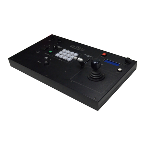
The two-handed controls on the system controller give you precise,
ergonomic, real-time control of the camera direction (pan and tilt and
camera functions (auto-focus and trigger). You can store up to eight
camera direction settings which you can return to later at the touch of a
button.

Police Head Quick Start Guide
3
Powering up and loading the head
There is no power switch on the camera head unit; the power is on
whenever the 24-volt power supply is attached and live. Similarly, there is
no power switch on the joystick control unit; it automatically gets its
power from its USB connection.
When you start MHC on the PC, it will automatically load the operating
software into the camera head unit, assuming that all cables are
connected.
The joystick control unit
Focus
Camera head
direction and
camera shutter
trigger button
Optional Zoom
control
Playback speedHead movement speed
Screen (displays the active head)
SELECT button (to select active head) and
BACK button to abort the current movement. RECORD
preset
Eight PRESETS (camera positions),
recordable and playable.
Auto-focus trigger
Camera shutter
trigger
Redundant

Police Head Quick Start Guide
4
Setting the soft limits
In order to prevent damage to cables and other equipment, you can set
software limits to the range of physical travel of the head movement.
To set the soft limits you use the MHC menu option Settings >
Preferences >Pan and Tilt.
Hint
The soft limits apply to any live motions that you perform with the
system, and to any existing positions that you have recorded
previously. If you tighten the limits, any existing position that is now
outside a limit will be not be accessible. The system will only go as
far as the limit allows.
If an axis is outside its soft limit then you will only be able to move
the axis towards the nearest soft limit.

Police Head Quick Start Guide
5
Police Head Quick Start GuidePolice HeadQuick Start Guide
Chapter 2 Recording and re-using static
camera positions
You can record the current head direction as a single “preset”, and then
return to that preset later at the touch of a button.
You can record up to eight presets on the joystick control unit, and more
in the MHC software, and the system remembers them even if you power
off. The following sections tell you how to record and use static camera
positions on the joystick control unit.
Recording a preset
1. Press the RECORD button.
2. If you haven’t done so already, use the system controls to go
to the camera direction that you want to record.
3. Press one of the eight PRESETS buttons.
The current settings are stored to that PRESETS button.
4. Repeat steps 2 and 3 to record additional presets if you want, using a
different PRESETS button for each position.
As long as you stay in Record mode, pressing one of the PRESETS buttons
will store the current settings to that button, overwriting the previous
settings for that button.
You record, use, and modify
presets by using the RECORD
and PRESETS buttons.

Police Head Quick Start Guide
6
Using a preset
1. Press one of the PRESETS buttons.
The camera points to the position that is stored under that
button.
2. Repeat step 1 to go to any other presets that you want.
As long as you stay in Playback mode, pressing one of the PRESETS
buttons will go to that camera direction.
Modifying a preset
1. Press the PRESET button for the position you want to
modify.
2. When the camera arrives at the preset position, use the
Joystick to fine-tune the settings the way you want.
3. Press RECORD then press the same PRESETS button
again.
The new fine-tuned settings overwrite the previous settings
for that button.
Hint
You do not need to wait until the head finishes going to a
preset position in order to go to another one. For example, if
you press the wrong PRESETS button by mistake you can
rectify it by immediately pressing the correct one. Pressing any
PRESETS button in Playback mode instantly aborts any current
action and goes to the new preset selection.
To immediately stop the head and abort the current action
without going to another preset, press the BACK button.

Police Head Quick Start Guide
7

8
Police Head Quick Start GuidePolice HeadQuick Start Guide
Appendix 1 Troubleshooting
Typical symptoms, causes, and actions
Symptoms Cause and/or action
Pod head did not
appear connected in
MHC
Check that all cables are connected, and all
devices have power.
Check you have added the correct IP address of
the Pod head in MHC.
If you have connected more than one Pod
heads, connected the MRMC system to
another local network, or moved the Pod head
between networks, check that correct addresses
have been entered in MHC.
A spanner( ) icon
appears with the Pod
head icon in the MHC
Main screen.
This can occur due Pan axis or Tilt axis error.
To resolve this, power cycle the head. The head
will take about 4 seconds to reappear
connected in MHC after power cycle.

Police Head Quick Start Guide
9
Notes

Police Head Quick Start Guide
10
Notes

Police Head Quick Start Guide
11
Police Head Quick Start GuidePolice HeadQuick Start Guide
Appendix 2 Panels
Panel summary
1. USB connector, for connection to the PC for using Nikon Camera
Control Pro software to control the camera features.
2. ETHERNET RJ45 connector. For connection to the head or larger
multi-component system. This Ethernet port is rated at 100 Mbits/
sec but can operate at lower speeds of 10 Mbits/sec or less.
3. POWER IN connector. The LFP requires a 3-pin, 24 Volt DC power
supply. For pin-out information see Power In connector on page 12.
4. VIDEO output connector for video signal from the camera. For
pin-out information see Video output connector on page 12.
1 2 3 4

Police Head Quick Start Guide
12
Connector pin-out information
Power In connector
Power to supply the camera unit, 24 Volts DC.
1. GND
2. 24VIN
3. N/C
Video output connector
The VIDEO output connector on
the camera unit is rated at 3 GHz.
1. VIDEO (inner)
2. GND (outer)
2
1
3
2
1

Police Head Quick Start Guide
13
Notes

Police Head Quick Start Guide
14
Notes

Police Head Quick Start Guide
16
Table of contents
Other MRMC Controllers manuals
Popular Controllers manuals by other brands

Rockwell Automation
Rockwell Automation MPMA instruction manual

Messana
Messana mZone installation guide

Baker Hughes
Baker Hughes Mooney 21 Series instruction manual

Douglas Lighting Controls
Douglas Lighting Controls BT-PP20-B installation manual

vivoVerse
vivoVerse vivoCube+ user manual

ABB
ABB PM554-T installation instructions