MRMC QUAD BOX User manual

ii
Quad Box Quick Start Guide
QSG Product Code: MRMC-1120-02
Product Covered: MRMC-2020-00
Modification date: 6 October 2021
© 2020 Mark Roberts Motion Control Ltd. All rights reserved.
No part of this publication may be reproduced, transmitted, or translated
by any means — graphical, electronic, or mechanical — including
photocopying, recording, taping, or storage in an information retrieval
system, without the express written permission of Mark Roberts Motion
Control.
Although every care has been taken to ensure that the information in this
document is accurate and up to date, Mark Roberts Motion Control
continuously strives to improve their products and may make changes to
the hardware, firmware, and software described in this document. Mark
Roberts Motion Control therefore cannot be held responsible for any
error or omission in this document.
All product names mentioned herein are the trademarks or registered
trademarks of their respective owners.
Contact information
Mark Roberts Motion Control Ltd.
Unit 3, South East Studios
Blindley Heath
Surrey
RH7 6JP
United Kingdom
Telephone: +44 (0) 1342 838000
Web: www.mrmoco.com
www.mrmocorentals.com

Quad Box Quick Start Guide
iii
Quad Box Quick Start GuideQuad BoxQuick Start Guide
Contents
Chapter 1 Quad Box Panel ............................................................. 1
Introduction to Quad box connections ..............................1
Notes on head-controller communication
methods..........................................................................1
Quad box connector summary ............................................2
Quad box connector pin-out information..........................4
Stepper motor connector.............................................4
Power 18-36 Volts connector ......................................4
Serial RS232 connector ................................................4
Trigger connector (trigger out and in).......................5
Adding a Quad box in Flair..................................................5
Troubleshooting Finding Boards in Flair ..................7
Changing IP Addresses.......................................8
Network Status.....................................................8
Appendix 1 Connecting Stepper Motors to Quad box ................... 11
Connecting any other stepper motor to Quad box .........11
Stepper drive pulse/direction .............................................11
Step/direction inputs..................................................12

Quad Box Quick Start Guide
iv

Quad Box Quick Start Guide
1
Quad Box Quick Start GuideQuad BoxQuick Start Guide
Chapter 1 Quad Box Panel
Introduction to Quad box connections
Quad box is an MRMC axis box with a Quad card inside, usually used to
drive four stepper motors.
The stepper motors can be of type:
23B
17B
34B
These motors run on a 48V voltage and can increase speed when supplied
with higher voltage. The Quad box can handle 26-36V; for higher voltage
of 48V, a Y cable can be added to supply extra power.
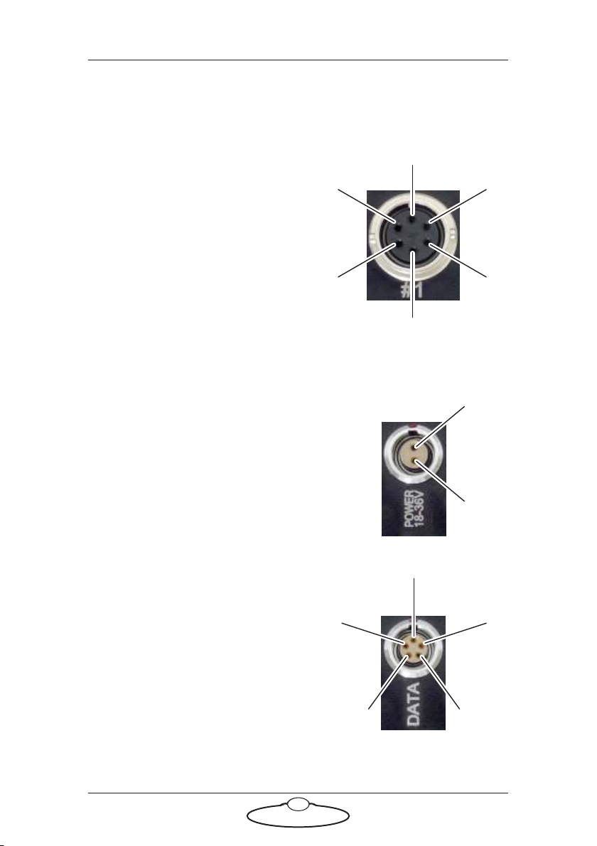
The Quad box has four stepper motor connectors. See Quad box
connector summary on page 2.
Notes on head-controller communication methods
Three types of connections between the head and controller are in
common use in MRMC equipment:
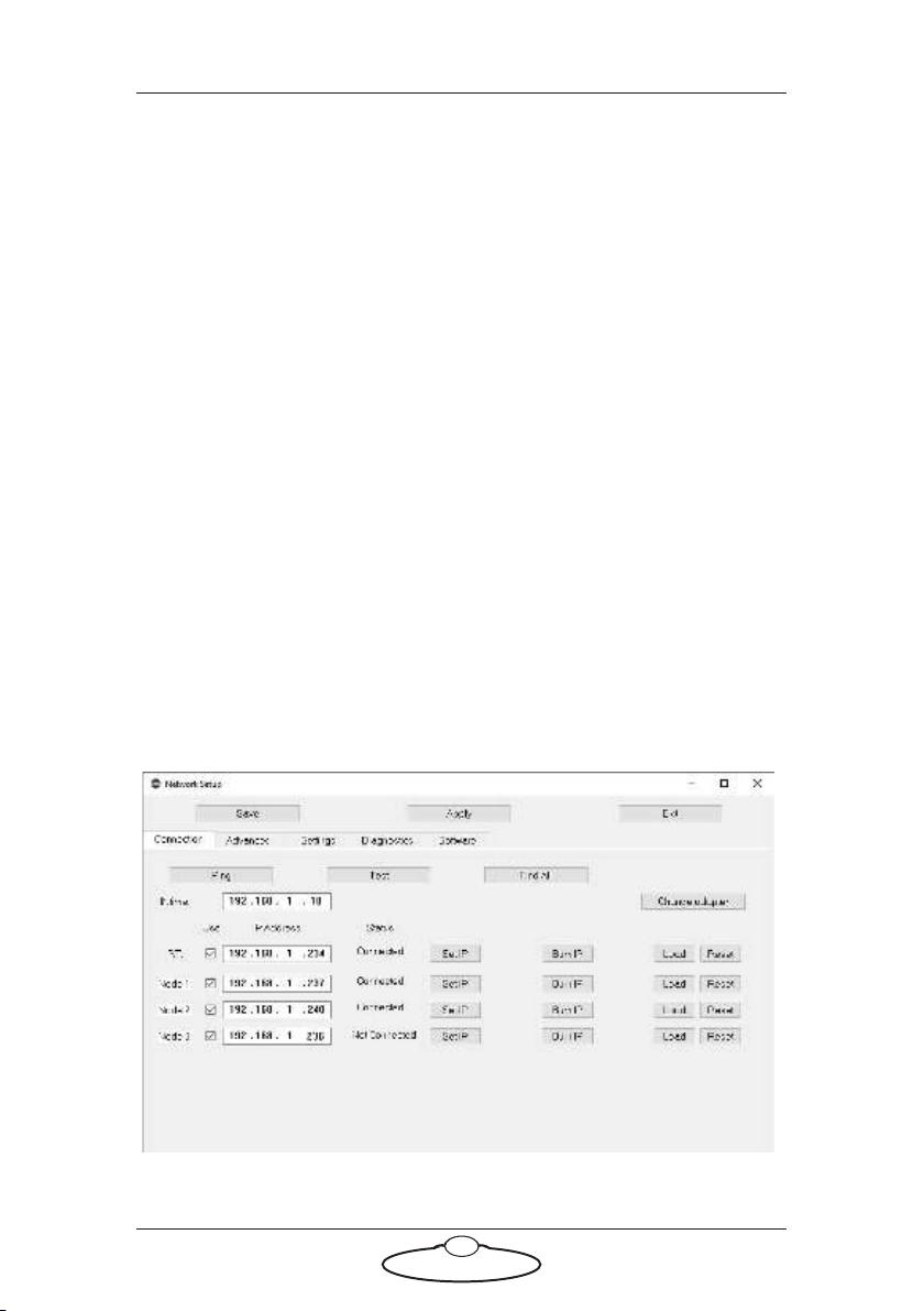
Ethernet: This is the most modern preferred method, and uses
standard Ethernet plugs, cables, hubs, and protocols.
DataLink: This is an MRMC proprietary connection type
based on a modified form of Serial RS232. You can connect
several DataLink devices together in a daisy-chain. DataLink is
robust and dependable and is still the preferred connection
method in environments with high electrical interference that
can cause problems on Ethernet networks.
Serial RS232: This is based on standard computer serial RS232
hardware and protocols.
Although many MRMC devices have built-in hardware for two or three of
the above connection methods, any controller that you use (such as the
MSA-20 Handwheels, LFP, Joystick Controller, or Mini MSA) must be
programmed at the factory for the connection method that you want to
use.

Quad Box Quick Start Guide
2
Quad box connector summary
1-4. #1 - #4 identical connectors for any stepper motors, such as PAN
and TILT in the head, track motors, and external Lens Control
Motors. For pin-out information see Stepper motor connector on page
4.
5. POWER 18-36V connector, for power input for the head.
When the power is on, the LED next to the POWER
connector lights up. For pin-out information see Power
18-36 Volts connector on page 4.
6. DATA connector. This is a Serial RS232 connector, for connection to
a controller using a Serial RS232 connection (as an alternative to an
Ethernet connection), and for updating the firmware in the Quad
box. For pin-out information see Serial RS232 connector on page 4.
1234
56 7
Quad box front
8
Quad box rear:
Power
LED

Quad Box Quick Start Guide
3
7. TRIGGER connector, for a bi-directional trigger signal
between the head and camera. When the trigger is
activated the LED next to the TRIGGER connector lights
up. For pin-out information see Trigger connector (trigger
out and in) on page 5.
8. ETHERNET RJ45 connector for controlling the head using an
Ethernet network connection. This Ethernet port is rated at 100
Mbits/sec but can operate at lower speeds of 10 Mbits/sec or less.
Trigger
LED

Quad Box Quick Start Guide
4
Quad box connector pin-out information
Stepper motor connector
The Quad box has four connectors for
stepper motors, typically used for Pan
and Tilt plus two for auxiliary devices
such as a track motor or Lens Control
Motor (LCM).
1. GND
2. 24V
3. 5V
4. Homing Datum
5. Step
6. Direction
Power 18-36 Volts connector
Two-pin DC input for powering the
head.
1. GND
2. +24V
Serial RS232 connector
This is a 5-pin Serial RS232 connector.
For usage see page 2.
1. Boot select
2. Tx (out)
3. Rx (in)
4. 5V
5. GND
5
6
1
3
2
4
2
1
4
5
3
2
1

Quad Box Quick Start Guide
5
Trigger connector (trigger out and in)
Trigger connection with Trigger Out
and Trigger In connections.
1. GND
2. Trigger Out
3. Trigger In/Out
4. +5V
Pin 3 can be trigger input or output
depending on a jumper setting in the
box which is set during manufacture. DSLR applications typically use two
trigger outputs, on pins 2 and 3; one for shutter and one for auto-focus.
Video applications typically use pin 2 for trigger output and pin 3 for
trigger input.
Adding a Quad box in Flair
When a new Turntable, other model mover or motor driven by a Quad
box needs to be added to a Flair system, there is a set of steps that need to
be followed to get this information on the nature of the item into Flair so
the network can detect it and load it on bootup.
Devices are added to the network as nodes identified by their IP address,
and it is possible that there may be duplicated IP addresses which will
need to be handled before this is possible.
The additional Quad box will need to have an Ethernet cable connected
to the Ethernet hub of the Flair system, and be powered.
1. Edit the file C:\Flair\Flair6\Flair.ini. This file is a text file
that you can edit with any text editor such as Notepad, either
directly or by using the Flair menu option Help >View .ini File.
You need to add or edit some lines in the file similar to the following
lines.
*NetworkBoards: 3
*NodeProgram3: Quad6Ether_II.btl
The keywords used in the above table are described below:
*NetworkBoards: This line shows the number of network
boards (nodes) in the system. You need to increase this by one
3
4
2
1

Quad Box Quick Start Guide
6
(1) to cater for the new Quad board. For example, if the
number of network boards was 2 increase it by 1 to make it 3.
*NodeProgram3: For the node that you are assigning the new
board to (node 3 in this case), add a reference to the node
program, or.btl file, that you want Flair to load on that node
when starting up. The .btl file is already supplied with Flair
so you don’t need to copy or download it from elsewhere. For
example, in this the new board is assigned to node 3, the .btl
file will be added to NodeProgram3.
Remember to save the file after you have edited it. When this Flair is
booted, Flair will attempt to load all the boards it has been informed
about in Flair.ini. It may fail to do so until correct connections are
made and correct IP addresses are set.
2. In the Flair menu, click on Setups >Network Setup. The first screen
is the Connection tab.
3. In the pop-up, click on the Find button.
4. In the Find results, find the IP address of the Quad box
(192.168.1.236 in this example – this is normally written on the box
at the factory), and copy it into the node that you assigned to the
Quad (Node 3 in this example):
5. In the Network Setup pop-up, click on the buttons Save and Apply.

Quad Box Quick Start Guide
7
6. Click Load and exit the Network Setup.
If the IP address is correct and does not conflict with any other IP
on the system, and you have put the correct software name in
Flair.ini then clicking on the Load button will load the board. On the
next restart, Flair should automatically recognise all the nodes and
load the .btl files into them.
Even if the IP address is correct and there are no conflicts of address, the
software may not be set correctly. If you now look at the Software tab it
will give the PC address of the software it has tried to load, and if you
click on Select, it will open the Btls folder and allow you to choose
another software file to load. You can then Reload and it will attempt to
load that new software. If this works you will need to put that software
name into Flair.ini to enable it to work next time you boot Flair.
Troubleshooting Finding Boards in Flair
Once you have physically connected with an Ethernet cable and powered
on the added board, and Network setups is open, if you click on Find, it
will broadcast a signal to see all the boards on the system, and will tell you
their IP address settings. If they do not appear, then they are not
connected or not powered; Or there is an IP address duplicated on two
boards!
You may then find you have conflicts in that the board you want to
connect will have the same IP address as the one already on the system.
The Find button will not find two boards with the same IP address. This
often occurs where you want to use the spare Ultibox from your Bolt as a
Note
Even though the specified .btl file might load, this does not
guarantee that it is the correct software for your Flair setup. Older
systems my need older versions of software loaded to work best.
Note
It may be necessary to unplug temporarily the other boards on the
system for the new board to show up!

Quad Box Quick Start Guide
8
model mover, and it has been set up to have the same IP, 192.168.1.237 as
the present Ultibox mounted on the Bolt arm.
Changing IP Addresses
The facility to change an IP address is built into the system, but to work it
must have the board you want to change already loaded.
If you find that whatever you do the new board does not appear, try
cycling the power to the network hub. Sometimes a hub may not “look”
for any additional devices unless rebooted.
Unfortunately, you cannot load two identical IP boards and then change
one, you have to load the incorrect board by doing a Find with other
boards not connected, to find its IP, then set that IP in the Network setup
screen, with its duplicated IP board disconnected. When you are
connected to it you can change the IP in Network Setups to a new IP and
press Set IP to make that the IP address Flair looks for, and press Burn IP
to burn that IP into the new board.
Once you have a new IP address burnt into the new board, put a new
label on it for future reference, and you should then be able to plug back
in any boards that were unplugged before making the change.
The list of IP addresses and boards loaded in sequence will be found in
the Network.ini file.
Because you now have the new board written into your Flair.ini it will try
to load every time you load Flair, and will give you a warning saying it did
not load if it is not plugged in on later shoots. Of course this does not
matter as the rest of the network will still work, you just need to know
Flair looked for it and did not find it.
Network Status
Under the Status heading in Network Setup, ‘Connected’ appears if it is
connected and being used by an axis in Flair. If it says ‘Unassigned’ it
means it is connected but you have not assigned that board to any axis in
Flair. Example, you have just added a node to be node 3 as a Quad box,
but you have no axis assigned to Network Node 3 in the Flair Screen. You
will need to assign your axes to that node for them to work.
There are coloured blobs in the bottom right of the Flair screen. A red
blob means its not connected to that node, a blue blob means its
connected but not assigned, a green blob means its connected and in use
by an axis.

Quad Box Quick Start Guide
9
Once you have added the board to Flair you may still need to set up the
axes. Refer to Flair manual for further details or the video “Flair Axis
Setup” in the Tutorial Videos section of Resources on www.mrmoco.com.

Quad Box Quick Start Guide
10
Notes

Quad Box Quick Start Guide
11
Quad Box Quick Start GuideQuad BoxQuick Start Guide
Appendix 1 Connecting Stepper Motors to
Quad box
Connecting any other stepper motor to Quad box
For a Stepper motor requiring 24V input, connect the V- to Pin 1 and V+
to Pin 2 on the Stepper connector. For a Stepper motor that requires more
than 24V use a Y cable, as follows. In this case, Pin 2 is not connected.
Also, if the motor driver requires 5V of Power, Pin3 in the stepper
connector can be used.
Stepper drive pulse/direction
The signal input of Step and Direction from the Quad box can be used for
interfacing the pulse/direction input clock type. Note that the CW/CCW
clock type is not supported by the Quad box.

Quad Box Quick Start Guide
12
Step/direction inputs
The motor angle step with the rising edge of the STEP signal, the
direction of rotation is controlled by the DIR signal.
Step and Dir outputs from the four motor ports are open collector
outputs. Absolute maximum current is 40 mA, so depending on what
voltage you use, and on your stepper driver electronics (diagram only
shows an example) you may need to add some resistance (R) on the cable.
It is possible to use higher voltage as long as the current is kept within the
limit, but it is highly recommend to use 5V output from MRMC Quad
board (pin3). Absolute maximum is 24V, and should never be exceeded.
Signal Signal value Meaning
STEP Rising edge Angle step
DIRECTION 0/open
1
Clockwise direction
Counterclockwise
operation

Quad Box Quick Start Guide
13
There is no enable line, therefore the enable input on the driver needs to
be wired permanently enabled.

Quad Box Quick Start Guide
14
Notes

Quad Box Quick Start Guide
15
Notes
This manual suits for next models
1
Table of contents
Popular DC Drive manuals by other brands

SEW-Eurodrive
SEW-Eurodrive MOVIDRIVE MD*60A Series operating instructions

Dover
Dover DESTACO CAMCO RNG Series Service manual

Festo
Festo DNCM POT Series operating instructions

BONFIGLIOLI
BONFIGLIOLI Agile AGL 401-05 quick start guide

Power Electronics
Power Electronics SD750 Series Hardware and installation manual

Festo
Festo DRVS-6 operating instructions

STG-BEIKIRCH
STG-BEIKIRCH M9 1000N Technical information and operating instruction

Danfoss
Danfoss VLT AQUA Drive FC 202 operating instructions

YASKAWA
YASKAWA PROFINET V1000 Product Transition Guide

unicraft
unicraft RFW 0,5, operating instructions

PI
PI MP116E user manual

ThyssenKrupp
ThyssenKrupp Mini gearless DAF270 operating manual