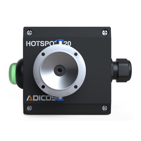
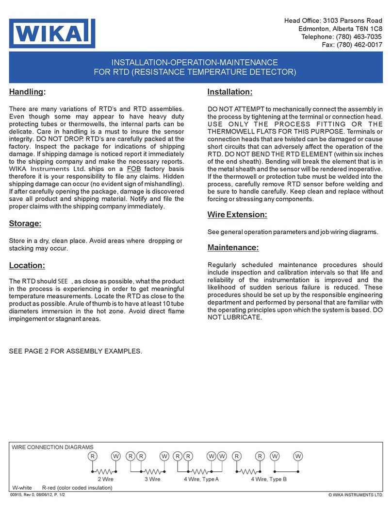
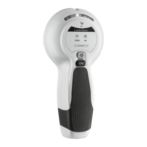
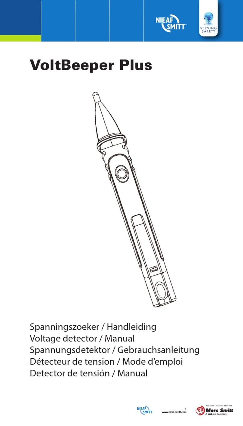
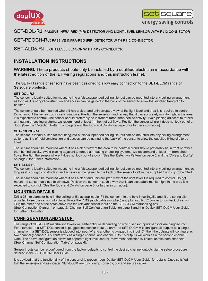
mru 400DH User manual

USER MANUAL 400DH
MRU GmbH, D-74172 Neckarsulm 1 / 14

USER MANUAL 400DH
2 / 14 MRU GmbH, D-74172 Neckarsulm
Manufacturer:
Legal notices / Intellectual property rights comments
Original user manual
© 2019 by MRU
No part of this manual may be published in any form (print, photocopy, elec-
tronic media or any other publication form) without a written approval by the
publisher.
All user trademarks and name mark descriptions, even those which are not
marked as such, are properties of the respective owners.
Edition: 2019-05-23, V01

USER MANUAL 400DH
MRU GmbH, D-74172 Neckarsulm 3 / 14
Content
1Introduction ...........................................................................................4
1.1. Intended Usage....................................................................................................4
1.2. The company MRU..............................................................................................5
2Security and safety directions for the analyzer..................................6
2.1. Safety manual .......................................................................................................6
2.2. Safety manual .......................................................................................................6
3Description.............................................................................................7
3.1. The hand detector probe 400DH ...................................................................7
3.2. Terms and window designation.....................................................................8
3.3. Context menu .......................................................................................................8
4Interchangeable sensors with technical specs....................................9
4.1. Leak detection on gas installations ...............................................................9
4.2. Spillage test on flue gas systems................................................................. 10
4.3. Verification of indoor climate ....................................................................... 11
4.4. Non-contact temperature measurement................................................ 12
4.5. Leak detection on air conditioners............................................................ 13
5Declaration of conformity.................................................................. 14

USER MANUAL 400DH
4 / 14 MRU GmbH, D-74172 Neckarsulm
1Introduction
This manual is an important part of your delivery. It explains the usage and
purpose of the Hand Detector Probe 400DH.
Please read this manual carefully and make yourselves familiar with the Hand
Detector Probe 400DH before using it.
The Hand Detector Probe 400DH may only be used by skilled personnel and
may only be used for its intended purpose.
Please pay special attention to the security and warning signs, to avoid per-
sonal injuries and damaging the product.
MRU can’t be held responsible for damages or injuries, by mot following the instruc-
tions in this manual.
Always keep the manual near you when working with the analyzer, to be able
to read instructions as needed.
1.1. Intended Usage
The hand detector probe 400DH cannot be used for personal protection or con-
tinuous monitoring tasks!
The hand detector probe 400DH is available with different interchangeable sen-
sor heads and can be used:
Gas Leak detector to detect gas leaks in an installation area
Spillage test to locate leaks at flue pipes
The hand detector probe 400DH detects measurement components and dis-
plays them.
The instrument was manufactured according relevant norms and regulations. It
must be used within its intended use.
The hand detector probe 400DH may not be modified from the design or safety
engineering.
Modifications of any kind by the user will render the declaration of conformity.
This hand detector probe meets the requirements of the
valid European and national regulations.
You can find the declaration of conformity in the appendix

USER MANUAL 400DH
MRU GmbH, D-74172 Neckarsulm 5 / 14
1.2. The company MRU
The 400DH is manufactured by the MRU GmbH in Neckarsulm, Germany
(founded in 1984), a medium sized company that specializes in developing, pro-
ducing and marketing high quality emission monitoring analyzers. MRU GmbH
manufactures a wide range of instruments, from standard analyzers up to tailor
made industrial analyzers
Plant 1: Sales, Service, R&D
Plant 2: Production
MRU GmbH
Fuchshalde 8 + 12
74172 Neckarsulm - Obereisesheim GERMANY
Phone +49 71 32 99 62 0 (Front office)
Phone +49 71 32 99 62 61 (Service)
Fax +49 71 32 99 62 20
Email: info@mru.de
Internet: www.mru.eu

USER MANUAL 400DH
6 / 14 MRU GmbH, D-74172 Neckarsulm
2Security and safety directions for the analyzer
2.1. Safety manual
All general information and safety precautions of MRU products are listed in the
supplied separate safety manual.
Therefore, this manual must be read and observed before the first use of the ana-
lyzer.
Instrument-specific safety and warning requirements in this manual are pre-
fixed before dangerous actions
2.2. Safety manual
The used categories of safety precautions are here explained once more
DANGER
Identifies an immediate, impending hazard that, if ignored, will
result in severe bodily injuries or death.
WARNING
Identifies an immediate, impending hazard that, if ignored, may
result in severe bodily injuries, material damage or death.
CAUTION
Identifies a possibly dangerous situation that, if ignored, may re-
sult in minor injuries.
ATTENTION
Identifies a possibly harmful situation that, if ignored, may result
in damages to the device or its surroundings.
NOTE
Identifies user tips and other especially important information.

USER MANUAL 400DH
MRU GmbH, D-74172 Neckarsulm 7 / 14
3Description
3.1. The hand detector probe 400DH
The detector hand probe 400DH must be connected to an MRU measuring device
(e.g. OPTIMA7) via the AUX plug.
The red markings of the socket on the measuring device and the plug on the detec-
tor hand probe 400DH must match.
Select the menu item "400DH (ext. probe)" in the measuring device.
…
"Connect sensor!" is displayed
The hand detector probe 400DH alone does not support measurement.
Each measurement function is implemented via the sensor to be plugged in.
In this operating manual only the hand detector probe 400DH with the available in-
terchangeable sensors is covered.
Please read the operating instructions for the basic operation of the measuring in-
strument.
The sensors are automatically recognized and can be easily operated.

USER MANUAL 400DH
8 / 14 MRU GmbH, D-74172 Neckarsulm
3.2. Terms and window designation
function
explanation
1
Connect probe!
In case of a communication error, check that the probe
is connected to the device via AUX connector and that
an interchangeable sensor is correctly plugged in.
2
SN
The serial number of the mounted sensor is displayed.
3
Warm-up time
Depending on the sensor, a certain time is required to
warm up the sensor to the required operating temper-
ature.
4
Numeric value
Display of the elapsed warm-up time
5
Function bar
Displays the functions available for the sensor used
3.3. Context menu
Depending on the sensor type used, different functions are offered in the context
menu:
function
explanation
Signal ON (Key F1)
If the sensor has a signal threshold, signal ON appears
in the context menu and on the display (Key F1).
With this function the signal is switched on.
Signal OFF (Key F1)
If the sensor has a signal threshold, signal ON appears
in the context menu and on the display (F1).
This function turns off the signal.
Zero point (Key F2)
This function is sensor dependent.
With this function the sensor is zeroed.
Max = 0 (Key F3)
The value Max is set to zero.
Reset
This function resets the graphic.
Setting
Depending on the sensor, the units and Signal thresh-
olds are set.
Printout (Dr)
Printout is generated, a printer is required for this
function.
Measurement menu
(ESC)
Exit measuring program
Info
The information (sensor name, serial number, firmware
version) about the sensor is displayed here.
choice
( >>) "Arrows right"
choice
( <<) "Arrows left"
Varies by sensor
e.g. HC402:
Switching between CH4, C3H8 and H2

USER MANUAL 400DH
MRU GmbH, D-74172 Neckarsulm 9 / 14
4Interchangeable sensors with technical specs
4.1. Leak detection on gas installations
The change sensor HC400 is used to locate gas leaks from CH4in installations. With
the change sensor HC401 it is also possible to search for C3H8and with the change
sensor HC402 it is also possible to search for H2gas leaks.
After the warm-up time of 30 seconds, the measuring window opens automatically
and the measurement begins.
If necessary, reset the zero point with the F2 key.
Slowly guide the sensor along the points to be tested. If there is a leak, the meas-
ured value changes and the flashing frequency of the red LED in the sensor foot in-
creases with the increase in the measured gas concentration..
Functions in the Context menu:
function
explanation
Signal ON (Key F1)
With this function the signal is switched on.
Signal ON (Key F1)
With this function the signal is switched off.
Zero point (Key F2)
With this function the sensor is zeroed.
Max = 0 (Key F3)
The value Max is set to zero.
Setting
Setting units and Signal thresholds
Printout (Dr)
Printout is generated, a printer is required for this
function.
Meas. menu (ESC)
Exit measuring program
Info
The information (sensor name, page number, firmware
version) about the sensor is displayed here.
Choice ( >>) ( <<)
„Arrows right/left“
HC401: Switching between CH
4
, C
3
H
8
HC402: Switching between CH
4
, C
3
H
8
and H
2
Settings: To trigger signals (signal ON /signal-OFF) for CH4, C3H8and H2the desired
signal thresholds must be set separately for each gas in the context menu/settings.
Gas
Adjustable Signal thresholds
CH
4
[ppm]
10 … 500 ppm
CH
4
[%]
0,001 … 0,050 %
CH4[% LEL]
0,02 … 1,14 % LEL
C
3
H
8
[ppm]
10 … 500 ppm
C
3
H
8
[%]
0,001 … 0,050 %
C
3
H
8
[% LEL]
0,06 … 2,94 % LEL
H2[ppm]
10 … 500 ppm
H
2
[%]
0,001 … 0,050 %
H
2
[% LEL]
0,03 … 1,25 % LEL
Technical Specification:
Sensor HC40X
range
resolution
response time
CH
4
-sensor
0 … 44.000 ppm
1 ppm
< 5 Sec.
C
3
H
8
-sensor
0 … 17.000 ppm
1 ppm
< 5 Sec.
H2-sensor
0 … 40.000 ppm
1 ppm
< 5 Sec.
DANGER
Danger due to improper use
Non-compliance with the measurement rules can result in fatal
accidents.
The meter may only be used for advertising purposes to locate
gas leaks in the installation area.

USER MANUAL 400DH
10 / 14 MRU GmbH, D-74172 Neckarsulm
4.2. Spillage test on flue gas systems
The change sensor RM400 is used for locating leaks in flue gas pipes.
Before measuring, remove the protective cap from the interchangeable sensor!
Slowly guide the sensor along the points to be tested. If there is a leak, the meas-
ured value changes and the flashing frequency of the red LED in the sensor foot in-
creases with the increase in moisture on the sensor surface.
For measurement, the sensor surface must be dry and at room temperature.
Functions in the Context menu:
function
explanation
Signal ON (Key F1)
With this function the signal is switched on.
Signal ON (Key F1)
With this function the signal is switched off.
Max = 0 (Key F3)
The value Max is set to zero.
Reset
This function resets the graphic.
Measurement menu
(ESC)
Exit measuring program
Info
The information (sensor name, serial number, firmware
version) about the sensor is displayed here.
Technical Specification:
range
resolution
response time
Sensor RM400
0 … 100
1
< 1 Sec.
NOTE
The RM400 operates on a conductive sensor surface, so do not
clean with alcohol or distilled water.
If necessary, clean the sensor surface with saline water and al-
low it to dry
DANGER
Danger due to improper use
Non-compliance with the measurement rules can result in fatal
accidents.
The meter may only be used for advertising purposes to locate
gas leaks in the installation area.

USER MANUAL 400DH
MRU GmbH, D-74172 Neckarsulm 11 / 14
4.3. Verification of indoor climate
The change sensor HM400 is used to check humidity, tempera-
ture, air pressure and dew point indoors.
With the sensor HM400 the measured values are displayed
without preheating time. Use the arrow left/right selection
keys to display the individual diagrams for each criterion and
the total display of all values as an overview.
Functions in the Context menu
function
explanation
Max = 0 (Key F3)
The value Max is set to zero.
Setting
Setting units
Printout (Dr)
Printout is generated, a printer is required for this
function.
Meas. menu (ESC)
Exit measuring program
Info
The information (sensor name, page number, firmware
version) about the sensor is displayed here.
Choice ( >>) ( <<)
„Arrows right/left“
Display switching between general view and view of
the individual criteria as individual diagrams
Settings:
Criterion
Adjustable units
Humidity
% (relative), g/m
3
(absolute)
Dew point
° C, ° F
Air pressure abs.
hPa, inHG, mmHG, mmH
2
O
Temperature
° C, ° F
Technical Specification:
Sensor HM400
Criterion
range
resolution
Humidity
0 … 100 % RH
0,1 %
Temperature
0 … +60 °C
0,1 °C
Air pressure
300 … 1.100 hPa
0,1 hPa
Dew point
calculated from humidity and temperature

USER MANUAL 400DH
12 / 14 MRU GmbH, D-74172 Neckarsulm
4.4. Non-contact temperature measurement
The IR400 interchangeable sensor is used for non-contact temperature measure-
ment.
Aim the sensor at the surface to be measured. The measuring distance depends on
the size of the surface to be measured, the closer the measurement becomes, the
more accurate it becomes. The minimum distance is approx. 1 - 2 cm.
Functions in the Context menu:
function
explanation
Signal ON (Key F1)
With this function the signal is switched on.
Signal ON (Key F1)
With this function the signal is switched off.
Max = 0 (Key F3)
The value Max is set to zero.
Reset
This function resets the graphic.
Setting
Setting units and signal thresholds
Printout (Dr)
Printout is generated, a printer is required for this
function.
Meas. menu (ESC)
Exit measuring program
Info
The information (sensor name, page number, firmware
version) about the sensor is displayed here.
Settings:
Signal threshold
30 °C … 380 °C
units
° C, ° F
Technical Specification:
range
resolution
field of vision
Sensor IR400
-70 … +380 °C
0,1 °C
35°

USER MANUAL 400DH
MRU GmbH, D-74172 Neckarsulm 13 / 14
4.5. Leak detection on air conditioners
The RF400 interchangeable sensor is used for leak detection on air conditioning
units.
The detected refrigerants are FCKW, HFCKW, FKW, HFKW and HFO.
After the warm-up time of 55 seconds, the measuring window opens automatically
and the measurement begins.
If necessary, reset the zero point with the F2 key.
Slowly guide the sensor along the points to be tested. If there is a leak, the meas-
ured value changes and the flashing frequency of the red LED in the sensor foot in-
creases with the increase in the measured gas concentration.
Functions in the Context menu
function
explanation
Signal ON (Key F1)
With this function the signal is switched on.
Signal ON (Key F1)
With this function the signal is switched off.
Zero point (Key F2)
With this function the sensor is zeroed.
Max = 0 (Key F3)
The value Max is set to zero.
Reset
This function resets the graphic.
Setting
Setting units and signal thresholds
Printout (Dr)
Printout is generated, a printer is required for this
function.
Meas. menu (ESC)
Exit measuring program
Info
The information (sensor name, page number, firmware
version) about the sensor is displayed here.
Choice ( >>) ( <<)
„Arrows right/left“
Switching between the gases
Settings:
To trigger signals (signal ON / signal -OFF), the desired signal thresholds must be
set separately for all gases in the context menu/settings.
Refrigerant/Gases
Adjustable signal thresholds
R134a [ppm]
5 … 100 ppm
H
2
[ppm]
5 … 100 ppm
R32 [ppm]
5 … 100 ppm
R1234ze [ppm]
5 … 100 ppm
Technical Specification:
Sensor RF400
Ref. refrigerant
R134a, H2, R32, R1234ze
Detect. refrigerant
FCKW, HFCKW, FKW, HFKW, HFO
Measuring range
0 … 1.000 ppm
Resolution
1 ppm
Detection limit
3 g/a (R134a)
Response time
< 3 sec.

USER MANUAL 400DH
14 / 14 MRU GmbH, D-74172 Neckarsulm
5Declaration of conformity
Table of contents