Bentel Security RAY60-S User manual

RAY60-S/RAY100-S
ISO 14001
9191.BNT2
ISO 14001
IT-52588
ISO 9001
9105.BNT1
ISO 9001
IT-52587
OHSAS 18001
9192.BSEC
OHSAS 18001
IT-60983
ITALIANO
Caratteristiche Generali
Raggio gemellare
Lenti di tipo asferico
Protezione contro la luce esterna
Ampia regolazione
Protezione contro il gelo e la rugiada
Distanza massima di arrivo del fascio: 10 volte
della gamma di protezione
IP54 (Protezione contro acqua e polvere)
Microprocessore e 4 canali
Descrizione Generale
ENGLISH
General Features
Twin beams
Aspheric lens type
External light protection
Wide adjustment
Protection against frost/dew
Maximum beam arrival distance: 10 times of
protection range
IP54 (Protection against water and dust)
Digital CPU and 4-channel
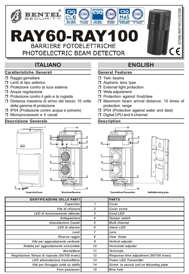
Description
IDENTIFICAZIONE DELLE PARTI PARTS
Coperchio 1 Cover
Vite di chiusura 2 Cover screw
LED di funzionamento ottimale 3 Good LED
Antiapertura 4 Tamper switch
Impostazione Canali 5 Multi channel
LED di allarme 6 Alarm LED
Lenti 7 Lens
Ricerca raggio 8 View nder
Vite per aggiustamento verticale 9 Vertical adjuster
Indice per aggiustamento orizzontale 10 Arrow for Horizontal adjuster
Morsettiera 11 Terminals
Regolazione Tempo di risposta (50/700 msec) 12 Response time adjustment (50/700 msec)
LED alimentazione trasmettitore 13 Power LED Transmitter
Vite per ssaggio unità su staffa 14 Screw to secure unit on Mounting plate
Foro passacavi 15 Wire hole
ISTISBL1RAY100-S 0.0 100212 ID CS3
2
1
11
3
12 4
5
6
7
7
8
9
10
Ricevitore/Receiver Trasmettitore/TransmitterCoperchio/Cover
5
4
13
Staffa/Mounting plate
7
7
8
9
10
14 14
15 15

Cautele nella Installazione
Per l’installazione delle barriere:
evitare che una forte luce abbagli il ricevitore o il¾
trasmettitore (raggi del sole o fari di automobili);
non installare le barriere su superci non stabili;¾
non installare le barriere in prossimità di alberi o¾
arbusti che possono interrompere il raggio delle
barriere stesse (considerare le stagioni);
non installare le barriere in luoghi dove vengano¾
continuamente spruzzate da acqua sporca o da
spruzzi di mare diretti.
Tempo di risposta
Per la regolazione del tempo di risposta agire
sul trimmer 12 come in gura a lato:
Corsa a tutta velocità: (6,9 m/s) – 50 ms;¾
Camminata con rapidi passi: (1,2 m/s) – 200 ms;¾
Camminata normale: (0,7 m/s) – 300 ms;¾
Camminata con passi lenti: (0,5 m/s) – 500 ms;¾
Scavalcamento di un recinto: (0,3 m/s) – 700 ms.¾
Distanza protetta ed estensione del raggio
Distanza protetta ed estensione del raggio:
Installazione
Installazione a parete:
rimuovere il coperchio dalla base (vite¾2) e fare
scorrere la piastra metallica sulla basa, dopo aver
tolto la vite 15;
staccare quindi la piastra dalla base. Far passare¾
i li attraverso le aperture della piastra e ssare
con 4 viti da 4 mm la piastra alla parete;
rompere i bassofondi sulla base per far passare i¾
li quindi ssare la base alla piastra (vite 15).
Dopo aver completato i collegamenti, regolate¾
l’allineamento, controllate le operazioni ed inne
ssate il coperchio sulla base (vite 2).
Installazione su paletto: ssare l’unità su un paletto
di diametro esterno da 40 a 46 mm.
Allineamento ottico
Leggere il voltaggio con un tester nelle apposite prese di
controllo (vedi gura sotto) per confermare l’allineamento
ottico ed ottenere la migliore afdabilità.
Alimentare l’unità dopo aver tolto il coperchio.1.
Cautions on Installation
Carefully work through the following steps:
Avoid strong light from sun, car head lights etc.¾
shining on Tx or Rx;
Do not install the unit on unsteady surface;¾
Do not install in a site where beam may be inter-¾
rupted by tree or plants, consider the seasonal
changes;
Do not install in a place where units may be¾
splashed continuously by dirty water or direct
sea spray.
Response time
Response time adjustment:
Run at full speed (6.9 m/s) – 50 ms;¾
Walk with quick steps: (1,2 m/s) – 200 ms;¾
Walking: (0.7 m/s) – 300 ms;¾
Walk with slow steps: (0.5 m/s) – 500 ms;¾
Go over a fence: (0.3 m/s) – 700 ms.¾
Protection distance and Expansion of beam
Protection distance and expansion of beam:
Installation
Wall mount:
remove cover from unit (screw¾2) and slide the
mounting plate to detach it.
Break grommet on mounting plate and pull wire¾
through it.
Secure the plate with 4 mm screws.¾
When exposed wired, break knockouts on the¾
rear of unit, pull wire through and attach it to the
mounting plate (screw 15).
After wiring is completed, adjust alignment, check¾
operation and attach cover.
Pole mount: Unit mounts to a 1.58” (40 mm) ~1.80”
(46 mm) external diameter pole.
Optical alignment
Read voltage from monitor jack with volt-meter
(digital) to conrm optical alignment and to obtain
the highest reliability (see gure below).
Supply power with cover detached.1.
A
DISTANZA PROTETTA/PROTECTION DISTANCE: L
MODELLO/MODEL LA
RAY 60-S
RAY 100-S
60 m
100 m
1.8 m
3.0 m
50 700
RESPONS TIME

Utilizzando il Ricerca raggio (2. 8) allineare le lenti
del trasmettitore con quelle del ricevitore. Le
lenti possono spostarsi orizzontalmente ±90° e
verticalmente ±10° per permettere all’unità di
funzionare in tutte le direzioni. Il Trasmettitore
o il Ricevitore dovrebbero apparire nei rispettivi
Ricerca raggio (8) nel mezzo dello specchio
interno.
Regolare il trasmettitore orizzontalmente e/o vertical-3.
mente per ottenere la migliore lettura del voltaggio.
Confermare il livello del raggio inserendo un4.
Tester nelle prese di controllo del Ricevitore.
Impostazione del canale
Questa funzione è usata per prevenire interferenze o
bypass dei raggi che possono accadere in una linea di
protezione o una linea ad unità sovrapposte. Impostare
il canale del raggio utilizzando il dipswitch (5).
Descrizione dei morsetti
Set Transmitter lens to Receiver lens by the view2.
nder. Look through view nder on either side and
line-up optics horizontally and vertically until the
opposite unit is visible. (Using the adjuster, the
lens can move horizontally (±90°) and vertically
(±10°) allowing the unit to work in all directions).
The opposite Transmitter or Receiver should ap-
pear on the view nder of inside middle mirror.
Adjust the transmitter’s horizontally and vertically3.
to get highest voltage reading.
Conrm the beam level by inserting a tester in 4.
monitor jack of receiver.
Channel setting
This function is used for the purpose of preventing
cross-talk or bypass of beams which may occur in
line protection or 2-stacked protection. Set beam
channel (dipswich 5).
Terminal assignment
1°canale/1 Ch 2°canale/2 Ch 3°canale/3 Ch 4°canale/4 Ch
RICEVITORE/RECEIVER
+
-
Regolazione verticale:±10°
Vertical adjustment:±10°
Regolazione orizzontale:±95°
Horizontal adjustment:±95°
Presa di controllo
Monitor Jack
Ricerca raggio
View finder
Presa di controllo voltaggio
/Monitor jack output voltage
3.1Vopiù/or over
3.0Vomeno/or less
Livello Raggio
/Beam level
Buono/Good
Regolazione/Readjustment
TAVOLA DI RIFERIMENTO/REFERENCE TABLE
DIMENSIONI
DIMENSIONS
177
86
80
15
26
37
4
234567
RICEVITORE/RECEIVER TRASMETTITORE/TRANSMITTER
Descrizione dei Morsetti Descrizione dei Morsetti
+ (Alimentazione) NO (Normalmente aperto)
- GND(Terra) Tamper ( Antiapertura)
NC(Normalmente Chiuso) Tamper ( Antiapertura)
(Tamper Tx: mors.3e4)
COM (Comune)
N. N.
15
26
37
4
Terminal configuration Terminal configuration
+ (Vcc:DC) NO (Normally open)
- GND Tamper
NC ( Normally Closed) Tamper
(Tx Tamper: term.3and 4)
COM (Common)
N. N.
1
-
NC COM NO TAMPER
+
234
1
-
TAMPER
+
Rx Tx

BENTEL SECURITY s.r.l. si riserva il diritto di modicare le speciche tecniche di questo prodotto senza preavviso.
BENTEL SECURITY s.r.l. reserves the right to change the technical specications of this product without prior notice.
CARATTERISTICHE TECNICHE
Modello RAY60-S RAY100-S
Portata (all’esterno) 60 m 100 m
Portata (all’interno) 120 m 200 m
Tipo di rilevamento Doppio raggio, pulsante
sincronizzato
Raggio infrarosso IR LED
Canali multipli 4 canali selezionabili
Tensione di alimentazione 10,8 ÷ 25V_
Corrente trasmettitore Max 60 mA
Corrente ricevitore
Tempo di risposta 50 ÷ 700 ms
LED Ricevitore Verde ON: sensibilità buona
Rosso ON: allarme
LED Trasmettitore (verde) Alimentazione
Uscita di allarme Scambio libero di relè
1C-30V(AC/DC) 1A max.
Reset: tempo di interruzio-
ne e ritardo (2±0.5sec)
Uscita antisabotaggio Microswicth (COM, NC)
Scambio libero di relè
1C-30V(AC/DC) 1A max.
Temperatura di funzionamento -20 ÷ +60 C°
Regolazione Raggi Orizzontale: 190° (±95°),
Verticale: 20° (±10°)
Materiale Coperchio: Policarbonato,
Base: ABS
Peso Tx: 305 g, Rx: 315g
Grado IP IP 54
PROBLEMI E SOLUZIONI
PROBLEMA CAUSA SOLUZIONE
Il LED non si
accende
Non alimentato Accendere
Sbagliata connessione
dei li o lo rotto, Corto
Controllare i li
Il LED di al-
larme non
si accende
quando il
raggio è in-
terrotto
Non alimentato Accendere
Sbagliata connessione
dei li o lo rotto, Corto
Controllare i li
Il raggio è riflesso su
un’altro oggetto e non
all’interno del ricevitore
Togliere l’oggetto ri-
ettente o cambiare la
direzione del raggio
Due raggi non sono inter-
rotti simultaneamente
Interrompere due rag-
gi simultaneamente
Il LED di al-
larme si ac-
cende conti-
nuamente
Il raggio non è allineato Controllare e regolare
di nuovo
Un oggetto fa da scher-
mo tra il Tx e l’Rx
Togliere l’oggetto che
scherma
Le lenti sono sporche Pulire le lenti con un
panno morbido
LED Allarme
intermittente
Errata connessione dei li Controllare di nuovo
Cambio voltaggio di ali-
mentazione
Regolare il voltaggio
Un oggetto fa da scher-
mo tra il Tx e l’Rx
Togliere l’oggetto che
fa da schermo
Una grossa fonte di di-
sturbo elettrico, come
un generatore, è troppo
vicino al Tx o all’Rx
Cambiare il luogo
dell’installazione
Installazione instabile
del Tx o dell’Rx
Rendere stabile l’in-
stallazione
Le lenti sono sporche Pulire le lenti con un
panno morbido
Allineamento sbagliato Controllare e regolare
di nuovo
Piccoli animali possono
attraversare i due raggi
Regolare il tempo di
risposta
TECHNICAL SPECIFICATIONS
Model RAY60-S RAY100-S
Protection range (Outdoor) 60 m 100 m
Protection range (indoorr) 120 m 200 m
Detection method Twin synchronized pulsed
beams
Infrared beam IR LED
Multi channel Selectable 4-channels
Supply Voltage 10.8 ÷ 25V_
Transmitter Current Less than 60 mA
Receiver current
Response time 50 – 700 ms
Receiver LED Green ON: sensitivity good
Red ON: alarm
Transmitter LED (green) Power
Alarm output Dry contact relay output 1C-
30V(AC/DC) 1A max.
Contact action: interruption time
& delay time (2±0.5sec)
Tamper output Dry contact, relay output
form (N/C). Contact capaci-
ty: 30V(AC/DC) 1A max.
Temperature range -20 – +60 C°
Beam adjustment Horizontal: 190° (±95°),
Vertical: 20° (±10°)
Material Cover: PC resin,
Base: ABS resin
Weight Tx: 305 g, Rx: 315g
IP Rating IP 54
TROUBLE SHOOTING
TROUBLE CAUSE SOLUTION
LED does not
light
No power supply Turn on the power
Bad wiring connection or
broken wire, Short
Check wiring
Alarm LED
does not
light when
the beam is
broken
No power supply Turn on the power
Bad wiring connection or
broken wire, Short
Check wiring
Beam is reflected on
another object and sent
into receiver
Remove the reflec-
ting object or change
beam direction
Two beams aren’t bro-
ken simultaneously
Broke 2 beams simul-
taneously
Alarm LED
continues to
light
Beam alignment is out Ch ec k an d adju st
again
Shading object between
Tx and Rx
Remove the shading
object
Optics of units are soi-
led
Clean the optics by a
soft cloth
Intermittent
Alarm LED
Bad wiring connection Check again
Change supply voltage Stabilize supply vol-
tage
Shading object between
Tx and Rx
Remove the shading
object
A large electric noise
source, sach as power
machine, is located ne-
arby Tx and Rx
Change the place of
installation
Unstable installation of
Tx or Rx
Stabilize
Optics of units are soi-
led
Clean the optics by a
soft cloth
Improper alignment Ch ec k an d adju st
again
Small animals may pass
throught the 2 beams
Set the response time
longer
This manual suits for next models
1
Other Bentel Security Security Sensor manuals

Bentel Security
Bentel Security Visus99 User manual

Bentel Security
Bentel Security ZT100H User manual

Bentel Security
Bentel Security BW-MCN User manual
Bentel Security
Bentel Security RAY60 User manual
Bentel Security
Bentel Security IR 360 User manual

Bentel Security
Bentel Security AMC10 User manual
Bentel Security
Bentel Security BL151 User manual
Bentel Security
Bentel Security FC450IB User manual

Bentel Security
Bentel Security FC450IB User manual
Bentel Security
Bentel Security BMD503 User manual
