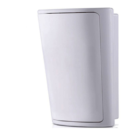
T.REXExit Detector Installation Sheet
Detector type Passive infrared
Filter technology Digital signal processing (DSP)
Detector lens Curtain type Fresnel lens
Detection range One hand: 3 m (10 ft). Whole body: 6 m (20 ft)
Power consumption 12 to 28 VDC, 50 mA
Piezo buzzer 90 db at 28 VDC, 5 to 28 VDC, 20 mA (XL and XL2 models only)
Main relay contacts SPDT, 1 A maximum at 30 VDC maximum
Main relay timer Adjustable, 1/2 to 60 seconds
Main relay recycle time Fixed, 3/4 second off
Lock control relay Solid state relay, N.C., 600 mA at 30 VDC, fixed time of 2 seconds. Available on LT2 and XL2 models only.
Tamper switch N.C., 100 mA maximum at 30 VDC maximum
Dimensions (H x W x D) 19 x 4.5 x 4.75 cm (7 1/8 x 1 3/4 x 1 7/8 in.)
Indicator light Red and green LED
Certifications UL 294, CE, FCC
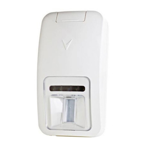
Adjusting the detection pattern
After you mount the T.REX and replace the cover, set the span and target direction
of the detection pattern by gently turning the louver direction screws. Stop turning
the louvers when you feel resistance. The louvers are located below the detector
lens on the barrel of the T.REX. The slots on the louvers indicate their position and
serve as an adjustment guide. The adjustment range is approximately 45°.
To adjust the detection zone towards or away from the door, rotate the detector
barrel. If you mount the T.REX directly above the door, direct the detection zone
away from the door. Rotate the barrel so that the lower edge of the detector lens is
approximately 1/4 in. above the edge of the case. Test the detection pattern and
zone by walk testing. Watch the LED for position detection. When you find the
correct detection pattern and zone, remove the cover and tighten the barrel locking
screw on the right side of the barrel, and replace the cover.
Warning: This detector provides fast detection and has not been designed to be
used in intrusion detection applications. This detector is designed to detect an
individual approaching a door. Normally, upon receiving the detector information,
the system supervising the door will bypass the door condition for a certain time to
permit the exit without causing a 'door forced open' alarm. This detector is designed
to be used on free exit doors. It has not been designed to unlock doors equipped
with door strikes. Locking and associated devices are generally governed by
regulatory bodies and should always be installed according to local regulations. In
most instances, there are strict limitations to installing this type of device on doors
used to exit. Be sure to check with local authorities for regulations before using any
such devices.
Table 2: Technical specifications
Part number Description
T.REX-LT Tamper and timer
T.REX-XL Tamper, piezo, and timer
T.REX-LT2 Tamper, timer, and 2 relays
T.REX-XL2 Tamper, piezo, timer, and 2 relays
Table 3: T.REX models
2
Jumper On (default) Off
LED LED follows the relay. LED stays on.
Fast High sensitivity.
LED is normally red.
LED is green on detection.
Normal sensitivity.
LEDis normally green.
LED is red on detection.
Latch Relay is on for timer setting. Relay follows detection, up to the
maximum timer setting.
Table 4: LED, fast, and latch jumpers
UL294 performance levels
Destructive attack: Level I
Line security: Level I
Endurance: Level IV
Standby power: Level I
This device complies with Part 15 of the FCC Rules. Operation is subject to the following two
conditions: (1) This device may not cause harmful interference, and (2) this device must accept any
interference received, including interference that may cause undesired operation. Changes or
modifications not expressly approved by Kantech could void the user's authority to use this equipment.
© 2019 Johnson Controls. All rights reserved. JOHNSON CONTROLS, TYCO and KANTECH are trademarks and/or registered trademarks.
Unauthorized use is strictly prohibited. DN1319-1908.
