MSA ML-3 User manual

cap lamp system
instructions
PITTSBURGH, PENNSYLVANIA,U.S.A.15230
Manufactured by
THIS MANUAL, INCLUDING THE WARNINGS AND CAUTIONS INSIDE, MUST
BE READ AND FOLLOWED CAREFULLY BY ALL PERSONS WHO USE OR
MAINTAIN THIS PRODUCT, INCLUDING THOSE WHO HAVE ANY RESPON-
SIBILITY INVOLVING ITS SELECTION, APPLICATION, SERVICE, OR REPAIR.
THIS CAP LAMP SYSTEM WILL PERFORM AS DESIGNED ONLY IF USED
AND MAINTAINED ACCORDING TO THE INSTRUCTIONS. OTHERWISE IT
COULD FAIL TO PERFORM AS DESIGNED AND PERSONS WHO RELY ON
THIS PRODUCT COULD SUSTAIN SERIOUS PERSONAL INJURY OR DEATH.
WARNING
The warranties made by MSA with respect to the product are voided if the
product is not installed, used, and serviced in accordance with the instruc-
tions in this manual. We encourage our customers to write or call for a
demonstration of this equipment prior to use or for any additional informa-
tion relative to use or repairs. Call 1-800-MSA-2222 during regular working
hours, or 1-800-MSA-5555 after working hours or during emergencies.
TAL 991 (L) Rev. 0 © MSA 1999 Prnt. Spec. 10000005389(S) 10011346
Doc. 10000004394
ML-3
1011346 9/7/99 12:40 PM Page 3

IMPORTANT
Pay close attention to Warnings and
Cautions in this manual. A WARNING
describes a condition that may cause
severe personal injury or death if
allowed to happen. A CAUTION
describes a condition that may cause
moderate injury or property damage if
allowed to happen.
1. An adequate mine lighting pro-
gram must include assessment
of mine lighting requirements,
integration of appropriate MSHA
regulation, selection of proper
equipment, and instruction and
training in use, inspection and
maintenance of equipment. (See
MSHA regulations, Title 30 CFR,
Part 19).
2. The cap lamp system will per-
form as designed only if used
and maintained according to the
manufacturer’s instructions.
Supervisors and users must
read and understand these
instructions before trying to use
or service this product. We
encourage our customers to
write or call their MSA distribu-
tor or call MSA Customer
Service for information on this
product before using it. To reach
the nearest MSA office, call 1-
800-MSA-2222 during normal
business hours, or 1-800-MSA-
5555 after hours or during emer-
gencies.
3. This cap lamp may be used only
after proper instructions and
training of its use.
4. Do not alter, modify, or substi-
tute any components without
the approval of MSA. Such alter-
ations will void the MSHA
approval for use in a hazardous
atmosphere.
5. Inspect the cap lamp and bat-
tery after each use and maintain
them according to MSA’s
instructions. Repairs must be
made by properly trained per-
sonnel only.
6. Follow MSA’s instructions for
first time and routine cap lamp
use. The battery must not be left
“on charge” indefinitely, (see
Storing Idle Batteries section).
Doing so may cause internal
gases to vent, which may lead
to accumulation of combustible
gases in the lamp room, dam-
age to the battery, or reduced
service life.
Failure to follow the above can
result in serious personal injury or
death.
GENERAL DESCRIPTION
The ML-3 Cap Lamp System consists
of cap mounted headpiece powered
by a Luminator®(lead-acid) battery.
The basis of the headpiece in which
some of the internal connections are
integral. A selector switch is incorpo-
rated, which can switch on either the
large main bulb or the small secondary
bulb. The main bulb is held in the
reflector in a focussed position by a
screwed boss form which a lead con-
nects to one of the cable termination
points. The small bulb holder is posi-
tioned at the top of the headpiece,
being connected internally to the cable
termination. The reflector fits over the
small bulb and has a rubber gasket
around the rim to seal against the
headpiece lens.
The battery covers are made of metal
or plastic. When the metal cover is
positioned on the top of the battery, it
2TAL 997 (L) Rev. 0 - 100113469
2
WARNING
TABLE OF CONTENTS
IMPORTANT .......................................................................2
GENERAL DESCRIPTION..................................................2
Remote Power Connections...........................................3
PREPARATION FOR USE...................................................3
Battery Charging.............................................................3
Storage of Batteries........................................................3
Filling Battery..................................................................3
Using the Remote Power Connection............................3
CAP LAMP SYSTEM..........................................................4
Replacing Battery (Metal Cover).....................................4
Removing Cable Wires from Battery..............................4
Replacing Battery Cover (Metal).....................................4
Replacing Battery (Plastic Cover)...................................4
USING ML-3 CAP LAMP SYSTEM....................................5
Repairing the Headpiece................................................5
REPLACING BULBS ..........................................................6
Removing the Bezel Ring ...............................................6
Replacing Main Bulb.......................................................6
Replacing Small Bulb .....................................................6
Reassembling the Bezel Ring.........................................6
Replacing the Reflector ..................................................6
TROUBLESHOOTING ........................................................7
ML-3 Cap Lamp System
1011346 9/7/99 11:43 AM Page 2

Preparing for Use
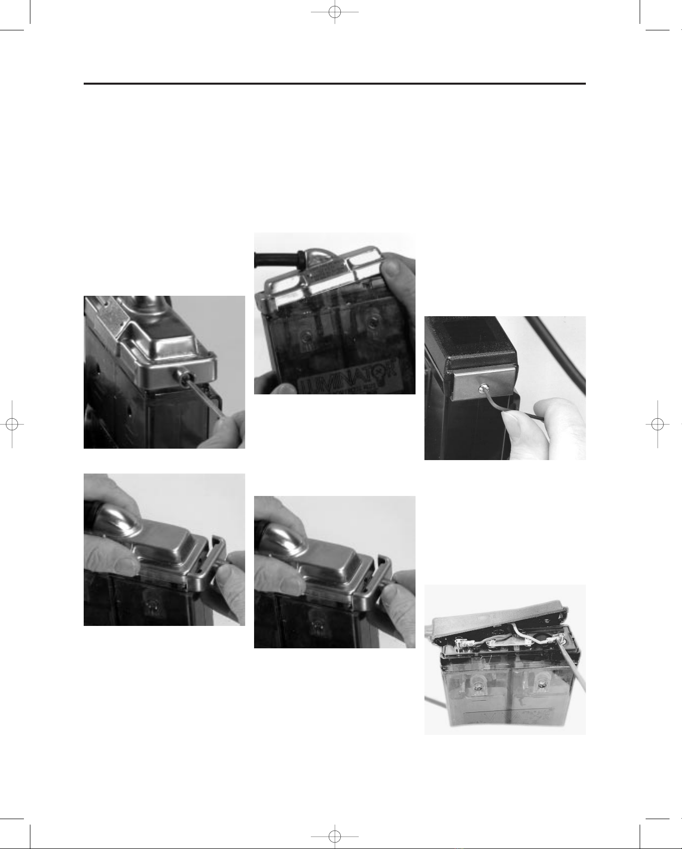
is further secured by a lock device
which fits at the end opposite to the
angle clamp. The lock device fits over
the end of the cover, and is secured in
position by a slotted screw. After the
screw is tightened, it can be filled with
wax to detect any unauthorized per-
son tampering with the battery.
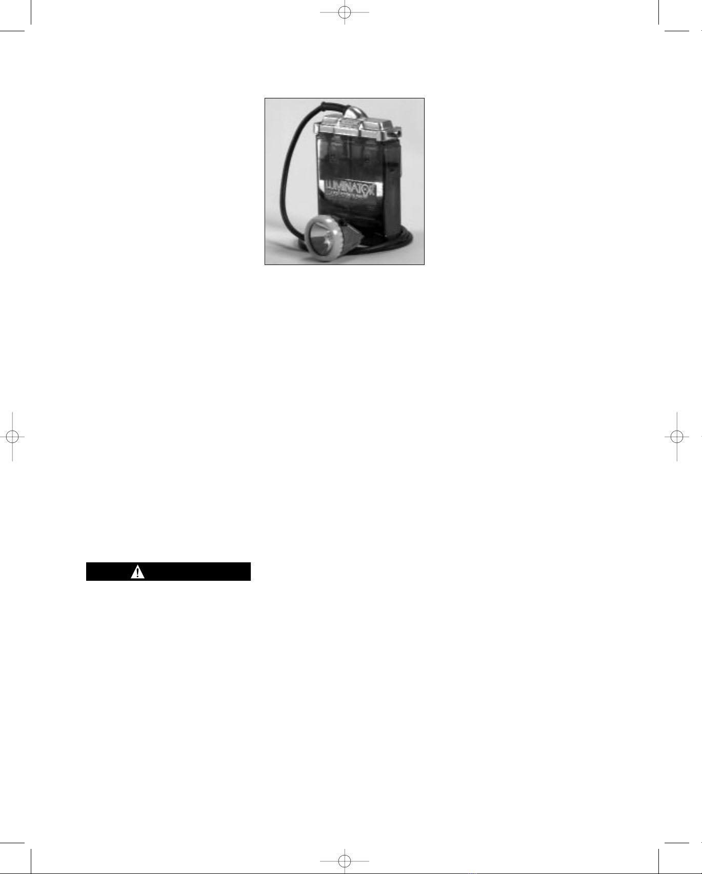
Depending on the Luminator battery
used, the cap lamp is designed to
operate at full brilliance for a minimum
of an 8-10 hour shift, with reserve
energy if needed. At the end of each
shift the battery is recharged in a sin-
gle- or multiple-station charging unit.
The Luminator Power Cell (13 AH) is
designed to operate at cycle routines
of 8-10 hours discharge/16-14 hour
recharge 5 days/week (max). If the
routines are increased, the Luminator
Power Cell Plus (16 AH) is recom-
mended. Battery charging connection
is made through the headpiece. Each
battery has a transparent case with
molded-in electrolyte level indicators
below the filling ports.
Remote Power Connections
(only available with plastic cover)
The Remote Power Connection allows
the Cap Lamp to be used as a power
source for an external remote device
while still operating as a light source.
MSHA regulation permits this configu-
ration as long as the external remote
device current requirement does not
exceed 275 milliamps.
If using the Remote with the ML-3
Cap Lamp, the Luminator Power Cell
Plus 16 AH battery is recommended,
due to higher battery demands.
However, the Luminator Power Cell 13
AH has been approved.
PREPARING THE ML-3 CAP LAMP
FOR FIRST TIME USE
Battery Charging
Every battery must be charged before
it is used for the first time.
1. Allow the battery to remain on
charge for 24 hours.
2. Top off each cell with distilled water
if necessary (see Filling Battery).
Never fill over top of fill line.
Note
Batteries which do not perform satis-
factorily, should be removed from
service and cycled - charged 16
hours, discharged 8 hours. Repeat
several times until battery responds. If
battery does not respond after three
or four cycles, it should be replaced.
3. After weekly shifts, the battery
should be placed on the charger
following the instructions included
with the charger, and left to charge
the remainder of the weekend.
4. If cap lamp needs cleaning, use a
mild detergent and wipe. Do not
submerge in water.
Storage of Batteries
All stored batteries with acid should
be boost charged for 24 hours every 3
months, and immediately before being
placed into regular service.
Recommended storage temperatures
32˚F to 80˚F.
Filling Battery
The electrolyte level should be main-
tained between the two lines below
the filling and venting hole i.e. slightly
above the top of the battery plate.
Normally topping up should not be
necessary more often than once every
4-6 weeks, and should always be car-
ried out when the battery is fully
charged. Only distilled or deionized
water should be used in topping off.
The electrolyte level of all batteries
should be checked once each
week, and after battery is charged.
Water only when battery is fully
charged. If the battery is over-
topped, there is a possibility that
electrolyte may leak out under cer-
tain conditions.
1. Fill the plastic bottle of the MSA
Filling Device (P/N 69422 or
469773) with distilled water only,
and place it at a convenient loca-
tion close to the batteries to be
watered.
2. Insert the nozzle or needle of the
Filling Tube into the small hole pro-
vided in the battery window.
Depending on the style of filling
device, squeeze the bottle or the
bottle handle.
3. Fill until the electrolyte level is
centered between the two scribed
lines below the cell window. The
battery may have to be tilted back
slightly to allow the water to flow.
4. Repeat this procedure in adjacent
battery cell.
The Electrolyte is corrosive and can
cause burns. Take proper precau-
tions to avoid skin and eye contact.
Contact MSA for battery Materials
Safety Data Sheet (MSDS). Phone
1-800-MSA-2222.
USING THE REMOTE POWER
CONNECTION
Note
If using the Remote Power Connec-
tions with the ML-3 Cap Lamp, the
Luminator Power Cell Plus 16 AH bat-
tery is recommended, due to higher
battery demands. However, the
Luminator Power Cell 13 AH has been
approved.
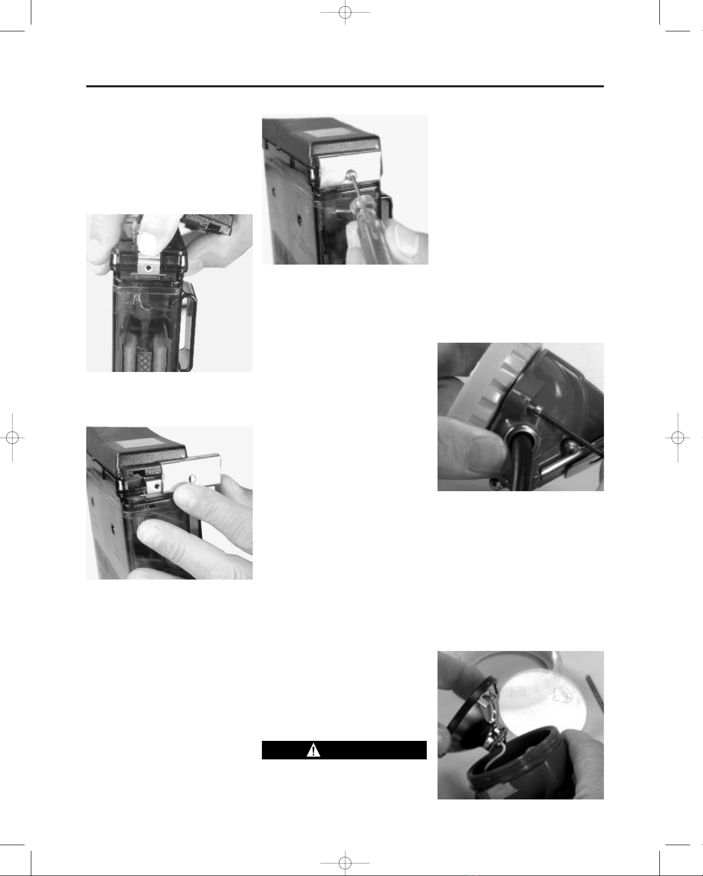
1. To access the battery power for
an external remote device, remove
the connector cover located on
the top of the battery. Keep the
cover for later use.
2. Slide the remote power device’s
connector onto the connector on
top of the battery until it stops.
3TAL 997 (L) Rev. 0 - 100113469
WARNING
CAUTION
Fill
Lines
1011346 9/7/99 11:43 AM Page 3

Cap Lamp System
3. At end of shift, or when finished
using the external device, remove
the external connection from the
battery top and reinstall the cover.
Place the battery on charge as
described in the Routine Battery
Maintenance section.
4. Refer to Illustrated Parts List for
replacement components.
CAP LAMP SYSTEM
Replacing Battery (Metal Cover)
1. To remove battery cover, remove
the wax seal (if applicable) from
the lock screw hole.
2. Remove locking clamp hex screws
with allen key.
3. Remove locking clamp.
4. Lift up locking clamp end of cover
and slide cover back and off battery.
Removing Cable Wires from Battery
1. Loosen cable clamp screws from
each terminal of battery. (Do not
lose the cable clamp screws.)
2. Lift each cablewire (lead) from bat-
tery terminal.
Replacing Battery Cover (Metal)
1. Attach cable wire (leads) to battery.
2. Connect brown conductor to posi-
tive battery pole.
3. Connect blue conductor to nega-
tive battery pole to ensure correct
polarity.
4. Tighten cable clamp screws with a
flat blade screwdriver. (Do not
overtighten.)
5. Turn battery so the vent holes are
facing you.
6. Place the battery cover end with
the rim to the left of the battery
vent holes.
Note
Ensure that the cable leads lie proper-
ly on the battery top without being
trapped or pinched.
7. Press down on the battery cover.
8. Place the lock clamp and screw
over the battery cover, with the
tab on top of the battery cover.
Note
The battery cover should be tested
immediately after reassembly on to the
battery, and at prescribed intervals, to
determine that there is no electrical
leakage beneath them. This is best
done with a 0 to 6 voltmeter (200 ohms
per volt). The test can be carried out on
the frame with the charge switched on,
by putting the voltmeter positive lead to
the positive spring contact on the
charging frame, and the voltmeter neg-
ative lead to the battery cover. This will
reveal a ‘negative’ leakage to the bat-
tery cover. Reversing the leads, and
putting the voltmeter negative on to the
charging frame negative key, will reveal
any ‘positive’ leakage. If either of these
faults are found, the cover should be
removed and the fault rectified.
9. Tighten the hex screw of lock-
clamp, add wax seal if applicable.
(do not overtighten).
Replacing Battery (Plastic Cover)
1. Remove the battery cover.
a. Use a 5/16” allen wrench to
remove the screws from the
cover clamps. Remove the
clamps from the battery case.
b. Lift the battery cover off the
battery. Each end will have an
adapter clip behind the cover
clamp. Keep these for further
use.
c. Loosen cable clamp screws
from each terminal of battery.
(Do not lose the cable clamp
screws.)
d. Lift each cable wire (lead) from
battery terminal.
Installing New Battery
1. Connect red conductor to positive
battery pole and black conductor
4
TAL 997 (L) Rev. 0 - 100113469
1011346 9/7/99 11:43 AM Page 4

ML-3 Repair
to negative battery pole to insure
correct polarity.
2. Tighten cable clamp screws with a
flat blade screwdriver. (Do not
overtighten.)
Reinstalling the Battery Cover
1. Check both ends of the battery for
the adapter clips.
Replace the battery cover. It must
fit squarely on top of the battery.
Slide a cover clamp on each end
of the battery and cover.
Note
The mounting hole in each clamp is
slightly off-center. Install the clamp so
that the hole is below center.
2. Install the two screws and tighten,
using the 5/64” allen wrench. (Do
not overtighten.)
USING ML-3 CAP LAMP SYSTEM
The ML-3 headpiece is made up of
the lamp-housing, which contains the
following parts:
— Bezel (ring)
— Lens
— Gasket
— Reflector
— Main Bulb
— Secondary Bulb
The on-off switch knob is located on
the headpiece. To operate the lamp:
1. Turn the switch knob clockwise to
main bulb or counterclockwise to
secondary bulb.
2. After use, turn the switch knob
until both bulbs are off.
Repairing the Headpiece
Only the small insulated screwdriver
should be used, as this allows the
screws to be secured tightly enough
without fear of a short circuit or other
damage. The switch should be placed
in the off position. If a bulb is being
replaced it should be tested in the
headpiece before final reassembly to
verify that it will light. When reassem-
bling the headpiece, it would be
ensured that the gasket is correctly fit-
ted around the reflector. The location of
the reflector is by two projections which
fit either side of the pin that rests
against the envelope of the pilot bulb.
The bezel ring should be screwed down
firmly and the lock pin placed so that it
fits into one of the recesses of the bezel
ring and firmly screwed tight. The coun-
tersunk hole in the locking boss can be
filled with the special sealing wax.
It is essential that all contacts in
the headpiece are tight, so that no
resistance is developed which
might increase the time necessary
to obtain an efficient charge or
might reduce the light output of the
lamp. In order to obtain the maxi-
mum light possible, the outside of
the lens glass should be cleaned
thoroughly.
The headpiece may be supplied
with a 1.0A main bulb, or with a
0.75A. Both bulbs are interchange-
able.
REPLACING BULBS (MAIN AND
SECONDARY PILOT BULB)
Removing the Bezel Ring
1. Remove wax seal (if applicable)
from lock screw.
2. Unscrew and back out lock screw
by using special allen key.
3. Unscrew and remove bezel ring
from headpiece housing.
4. Remove glass (lens) and reflector
with sealing channel from head-
piece housing.
Note
Inspect all parts for cracks or other
damage.
Replacing the Main Bulb
1. Lift reflector out of housing, mak-
ing sure not to break the bushing
connection.
5TAL 997 (L) Rev. 0 - 100113469
WARNING
1011346 9/7/99 11:43 AM Page 5

ML-3 Repair
2. Unscrew reflector from bushing by
holding bushing and unscrewing
reflector.
3. Remove main bulb.
4. Place the new main bulb through
the reflector.
5. Hold the bushing and screw the
reflector onto the bushing. (Do not
overtighten.)
Replacing Secondary Bulb
1. Remove bezel ring (use Remove
Bezel Ring procedures).
2. Remove reflector from headpiece
housing.
3. Unscrew secondary bulb from
side socket assembly of head-
piece housing.
4. Thread the new secondary bulb
into the socket assembly. (Do not
overtighten.)
5. Place the hole in the reflector over
the secondary bulb.
6. Reassemble the glass (lens) and
bezel to the headpiece assembly.
Reassembling the Bezel Ring
When the lens is in position over the
reflector, bezel ring is screwed firmly
in place. The bezel ring is locked in
position by a hex headed lock screw
that fits into a countersunk hole and
then enters one of the slots in the
bezel ring. The countersunk hole
enclosing the lock pin can be filled
with wax if desired.
Replacing the Reflector
1. Remove the bezel ring and lens.
2. Remove the reflector from main
bulb bushing.
3. Remove gasket around reflector.
4. Place the gasket around the new
reflector. Ensure the gasket is in
place all the way around reflector.
5. Thread the reflector onto the
bushing.
6. Reassemble the lens and bezel
ring (see Reassembling of Bezel
Ring).
6
TAL 997 (L) Rev. 0 - 100113469
1011346 9/7/99 11:44 AM Page 6

8
1 Lamp Housing..................................
2 Bezel Ring ........................10014213
3 Glass Lens........................10014214
21 Sealing Channel................10014216
22 Reflector...........................10014210
26 Small Bulb Socket
31 Main Bulb 4V 1.0A ...........10014215
Halogen ............................................
31 Main Bulb 4V 0.75A .........10014212
Halogen (not shown)
32 Small Bulb 4V 0.46A.........10014217
33 Prefocus Reflector
Bush & Connection...........10014222
124 Cable ................................10014218
27 Large Bulb/Switch Connection
Assembly
28 Small Bulb/Switch Connection
Assembly
29 Switch Connection
30 3/16” B HD Screw
16 Positive Contact Sealing Washer
5 Switch Knob
6 Switch Knob Sealing Washer
7 Switch Blade
8 Switch Blade Cowl
9 Grub Screw
16 Positive Contact Sealing Washer
19 Charging Contact Screw
24 Large Bulb Socket Block
25 Large Bulb Socket Screw
14 Lock Spring
15 Lock Barrel
17 Lock Contact
18 Lock Contact Screw
23 Lock Contact Sealing Washer
10 Cap Clip
11 Cap Clip Screw
12 Cap Clip Nut
13 Spring Washer Steel
131 Battery Cover Assembly (Metal)
132 Cable Gland
135 Lock Clamp & Bush Assembly
137 Battery Lock Screw
138 Insulating Pad PVC
139 Battery Top Gasket
140 Blank Number Check
141 Flat Head Rivet
142 Cable Lock
122 Allen Key for Lock Pin
155 Allen Key for Battery Cover Lock
130 Key for Cable Gland
Screwdriver (not shown)
Headpiece Contact Kit 10014519
Switch Knob Kit 10014515
Charging Screw Kit 10014517
Lock Contact Kit 10014516
Cap Clip Kit 10014518
Battery Cover Kit (Metal) 10014220
Tool Kit 10014219
Item List
7
TAL 997 (L) Rev. 0 - 100113469
ML-3 Diagram
2
3
21
22
31
32
26
27
28
5
6
29
25
24
20
15 14
1011
182317122
130
1
4
13 12
16 19
138
124
132
135
141 131 137
140 155
139
142
9
7
30
8
33
Note: Only certain replacement items above may be purchased individually. All others, as
noted, must be purchased in kit form.
1011346 9/7/99 2:05 PM Page 5

Troubleshooting
PROBLEM CAUSE
Bulb glows dimly, flickers or fails 1. Low battery capacity
a. Observe the electrolyte level in the cell windows and make certain level is
between the two scribed lines on the cell windows.
b. Continuous use of battery that has not been fully charged will cause it to
lose its capacity. This may be corrected by cycling the battery several times
(discharge 8 hours and recharge 16 hours). Repeat this procedure 3 times. If
battery does not respond, replace with a new one.
c. Battery not charged.
2. Loose connections
a. Gently wiggle or pry each connection on top of the battery to make sure it
is tight and working properly.
b. Check the cables for broken conductors by twisting or pulling it at various
points along its length.
c. Check the headpiece terminals and the electrical connections inside the
headpiece in the same manner as those on the battery.
d. Make sure the bulb is secure and making good contact.
e. If the light flickers or dims when any of the preceding items are being
checked, that item should be repaired or replaced.
f. If battery appears warm on charge, this is normal and is not necessarily an
indication that anything is wrong with the battery.
3. Electrolyte Level
a. Check at least once each week to see that the electrolyte level is between
the two scribed lines on the cell window.
Battery not holding a charge a. Make sure charger output is correct.
during shift b. Check electrolyte level after charge.
c. Make sure connections between headpiece and battery are good; charging
rack connections are good.
d. Make sure stored batteries are boost charged before placing into service.
Battery Capacity: a. 13 AH battery recommended for 8-10 hour discharge/16-14 hour
Loses charge during weekly use charge, 5 days a week. Use the 16 AH Luminator battery for greater cycle
routines.
b. Check charger.
c. Check battery connections.
ML-3 Repair
9TAL 997 (L) Rev. 0 - 100113469
1011346 9/7/99 11:44 AM Page 9

The Following Assemblies have Battery with Acid and 13 Amps
Complete Cap Lamp Headpiece and Cover
Assembly Number Assembly Main Bulb Amp Battery Cover
10010590 10010624 1.0 Stainless Steel
10010592 10010625 .75 Stainless Steel
10010594 10010626 1.0 Plastic
10010596 10010627 .75 Plastic
10010598 10010628 1.0 Plastic w/Remote
10010610 10010629 .75 Plastic w/Remote
The Following Assemblies have Battery with Acid and 16 Amps
10010612 10010624 1.0 Stainless Steel
10010614 10010625 .75 Stainless Steel
10010616 10010626 1.0 Plastic
10010618 10010627 .75 Plastic
10010620 10010628 1.0 Plastic w/Remote
10010622 10010629 .75 Plastic w/Remote
1011346 9/7/99 11:44 AM Page 10
Table of contents
Other MSA Outdoor Light manuals