MSD Digital Shift Light
PN 89631
WARNING: When installing the Shift Light disconnect the battery cables. When disconnecting,
always remove the negative cable first and install it last.
Parts Included:
1 - Shift Light
1 - Mounting Bracket
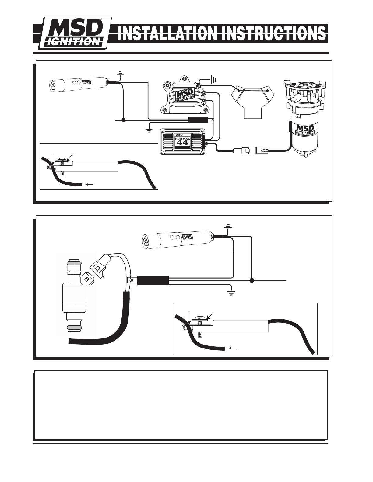
1 - GMR Pickup, PN 8918
2 - Washers
1 - Brass Screw
1 - Parts Bag
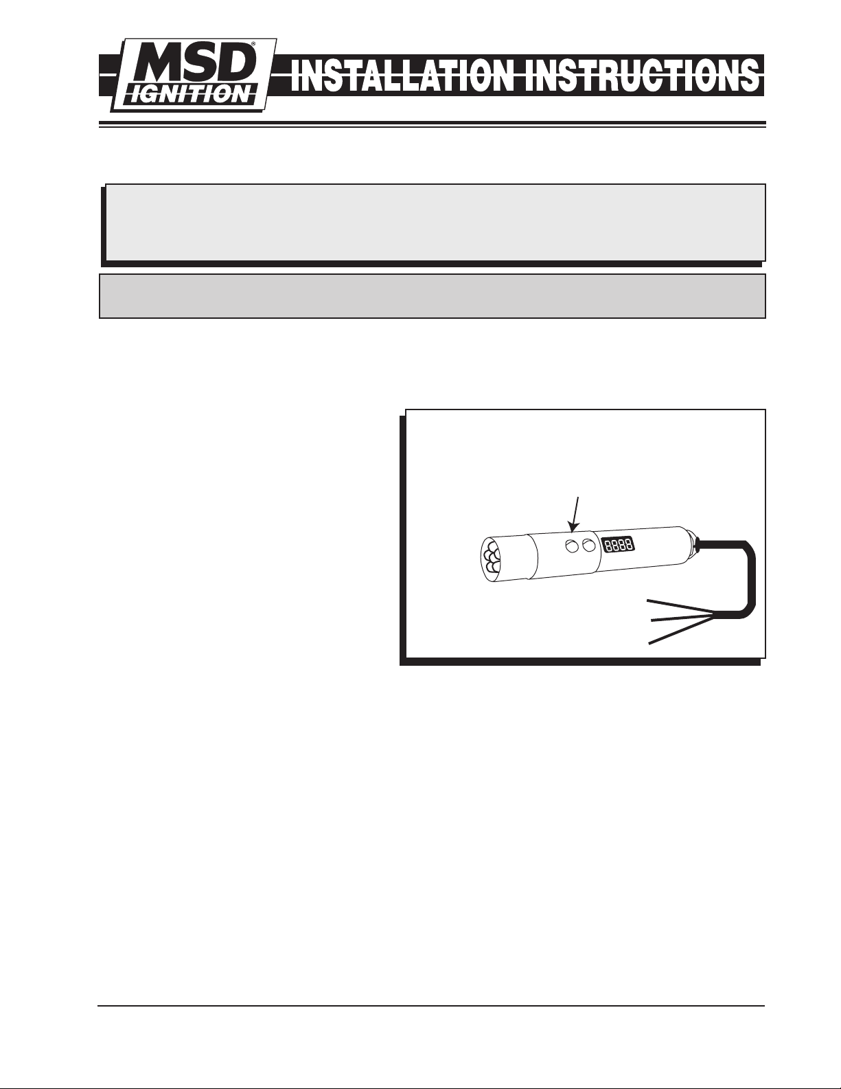
UP
MODE
DOWN
PROGRAMMING
BUTTONS
RED TO SWITCHED 12 VOLTS
GREEN TO TACH SIGNAL
BLACK TO GROUND
PROGRAMMING
CY - Cylinder Count
12, 10, 8, 6, 6 odd, 4, 2, 2 odd, 1
LuL - Light Intensity
Scale of 9-0 Bright to Dim
Use Up/Down
buttons to adjust
cylinders, intensity
and rpm points.
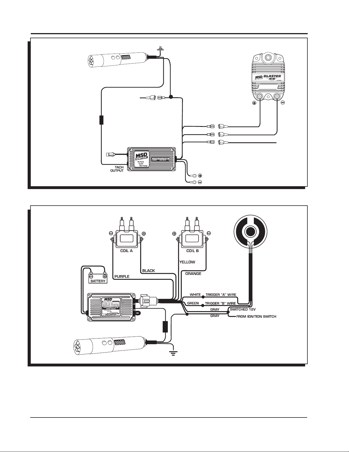
Figure 1 Digital Shift Light Wiring and Programming.
PROGRAMMING
By pressing the two buttons simultaneous-
ly, you get the Shift Light into the different
programming modes.
RPM: To adjust the rpm, press the two but-
tons until the rpm shows. Notice that all
of the numbers flash. Adjust the rpm then
push the two buttons again to move to the
next mode. The rpm can be set up to 16,000
rpm. Once you go over 9,900 rpm, the dis-
play will show 1,000 indicating 10,000 rpm
and higher.
Cylinder Count: The display will read CY
and allow you to select between one to 12-
cylinder engines using the Up/Down but-
tons. On single cylinder two stroke or four
stroke applications that fire every revolution
(waste spark systems) the shift light should be programmed for two cylinder operation for correct op-
eration.
Intensity: Control the intensity of the LED and read out. Hold the buttons until LuL displays. Use the
buttons to select from 9 (brightest) to 0 to turn off the shift light.
Self: Self mode will walk through all of the settings programmed into the light. It will first show the
rpm shift value for the shift light, the cylinder count and light intensity. Start the test mode by push-
ing either button once Self is displayed. To reset the Self mode, push either button when SELF is
displayed, or turn the power Off.
Each time the DSL is powered on, the LED will display the program values that are set.
INSTALLATION
The Shift Light installs easily with the GMR Pickup or through the tach output terminal of an MSD Ig-
nition Control or aftermarket ECU. It will accept a trigger signal rated from 0-24 volt amplitude. Never
connect the Green Wire directly to the coil negative terminal.
If an ignition control or aftermarket ECU are not being used, the GMR pickup must be connected.
IMPORTANT: Do NOT connect to the coil (-) terminal. The supplied GMR pickup must be used
when installing the Digital Shift Light unless the rpm signal is coming from the tach
output of an MSD Ignition or aftermarket ECU. Damage to the DSL will occur if con-
nected to a high voltage trigger source.
MSD IGNITION • www.msdignition.com • (915) 857-5200 • FAX (915) 857-3344