MSD Atomic LS EFI 2950 User manual

Atomic LS EFI
Master Kit LS2/LS3, PN 2950
Parts Included:
2 – Integrated Fuel/ECU Rail Assemblies
1 - Power Module
1 - Handheld Monitor
1 - Wideband O2 Sensor, Bung and Plug
2 - MAP Sensor Adapter Harnesses
2 - Camshaft Sensor Harnesses, 1x and 4x
2 - Crankshaft Harnesses, 24x and 58x
4 - Injector Harnesses
1 - IAT Sensor and Grommet
Thank you for selecting the Atomic LS EFI System! MSD’s Atomic EFI systems are designed with
two major goals; to simplify EFI and deliver better overall performance from your engine. Simplicity
is achieved through wired-less technology to ease installation plus the Atomic is simple to program
with no PC required! Performance is delivered through advanced control of the fuel and ignition, just
as you’d expect from MSD.
1 - TPS Sensor Harness
2 - 90° -6 AN fittings
4 - -6 AN fittings
1 - 15" High Pressure Fuel Hose
2 - Fuel Hose Clamps
4 - Installation Brackets
4 - Intake Manifold Bolts
8 - Injector Retainers
8 - 8/32" Socket Head Cap Screws
1 - 4G Micro SD Card
4 - Grommet, Sleeves and Mounting Screws
Not legal for use on pollution controlled vehicles: The MSD Atomic LS EFI system is not CARB
approved for use on emission controlled vehicles. This system is designed to control the EFI and
ignition on LS based engines being retro-fit into older vehicles that do not require emission controls.
Parts Required, Not Included:
• Injector O-Rings
• Fuel System: Fuel Pump, Regulator, Line
•LS1 and LS6 Installation Kit - PN 2955
For use with Master Kit PN 2950. Provides the
correct brackets and EV-1 injector connectors
for the early car intake manifolds identified by
a 3-bolt throttle body.
• Thread Sealer for Intake Bolts
Installation of this product requires detailed knowledge of automotive systems
and repair procedures. Installation of fuel system parts and any fuel tank
modifications must be carried out by a qualified automotive technician. Installation of fuel system
parts requires handling of gasoline. Ensure that work is performed in a well ventilated area with an
approved fire extinguisher nearby. Extinguish all open flames, prohibit smoking and eliminate all
sources of ignition in the area of the vehicle before beginning the installation.
When working with fuel systems, eye goggles and other safety apparel should be worn to protect
against debris and sprayed gasoline. The finished work must be thoroughly checked to ensure
there are no fuel leaks.
DANGER
CAUTION
WARNING
NOTICE

2 INSTALLATION INSTRUCTIONS
CAPABILITIES
The Atomic LS EFI system is designed to fit OE intake manifolds, as well as some aftermarket intakes.
The Atomic EFI is a self-tuning fuel system that continuously adjusts after the basic configuration is
complete. There is no laptop programming. Based on the engine descriptors you input, the Atomic
will automatically create a base fuel map to get the engine running. Once running, the self learning
system will optimize those maps resulting in the best performance possible. If you change altitude,
outside temperature, or other factors the Atomic will adjust accordingly, on the fly. This ensures that
your engine will produce excellent driveability at all times, even if you drive from the sunny coast to
the cold mountains.
The Atomic LS fuel injection system is capable of running the fuel and ignition system of most LS engines.
The system incorporates OE style connectors to use with the factory sensors on the engine. The only
external sensor required to add is the supplied Wide-Band Oxygen sensor.
There are four main components of the Atomic LS system; the driver’s side and passenger side integrated
fuel rails, the Power Module and the Handheld Monitor. The ECU of the system is divided onto the fuel
rail assemblies and communicate to each other, as well as the Power Module, through MSD’s proprietary
CAN-Bus technology.
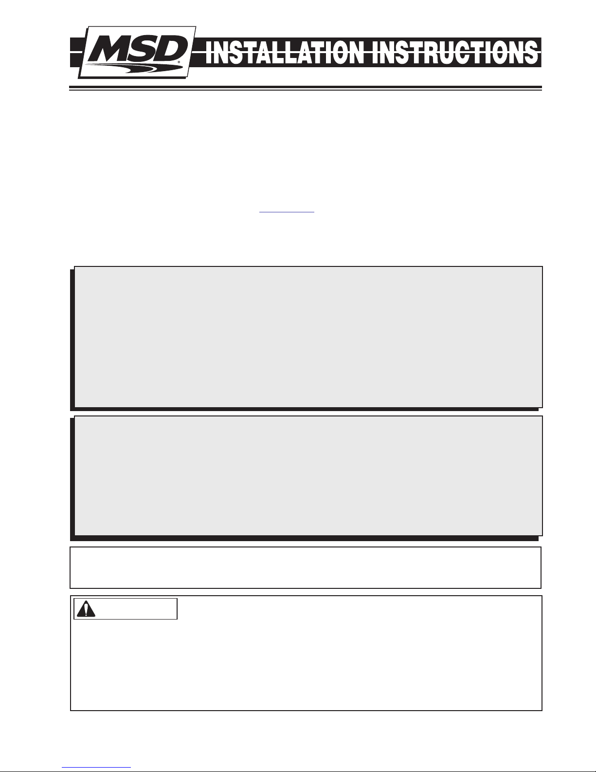
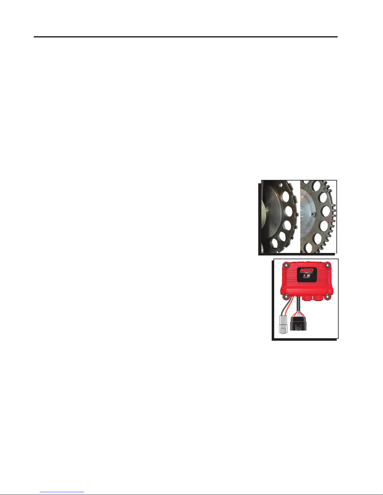
Crankshaft Trigger Wheel ID: It is important to know what crankshaft
trigger wheel your engine is fit with. There are two; early engines used a
24-tooth wheel and later model engines use a 58-tooth wheel. These can
be identified by removing the crank sensor (located behind the starter)
and looking inside the engine (see photo at the right).
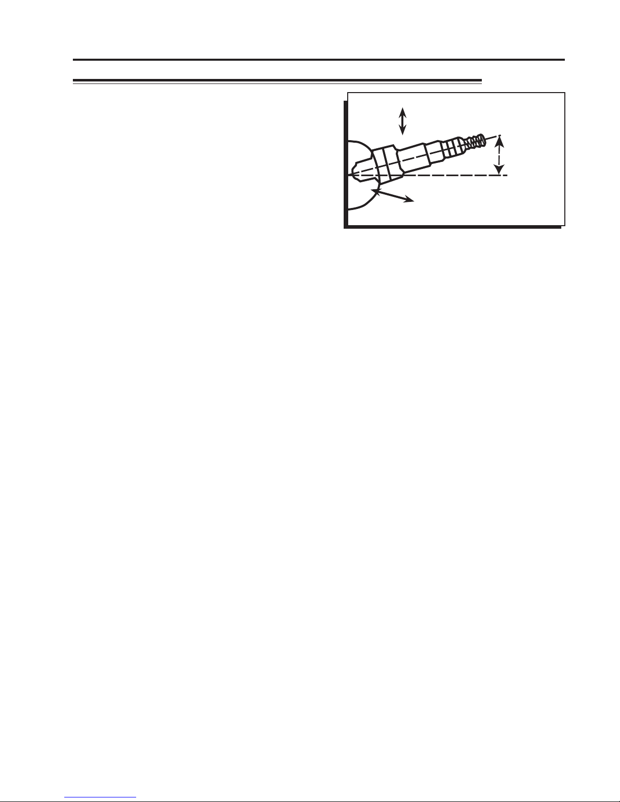
Fuel/ECU Rails: The unique fuel rails of the Atomic LS EFI system also
incorporate the ECU of the system. The two banks receive power from the
Power Module and communicate to the system through MSD’s CAN-Bus
network. To install the rails to the intake manifold, the covers will need to be
removed (which is outlined in the instructions).
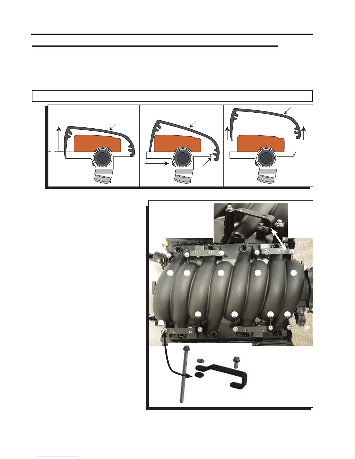
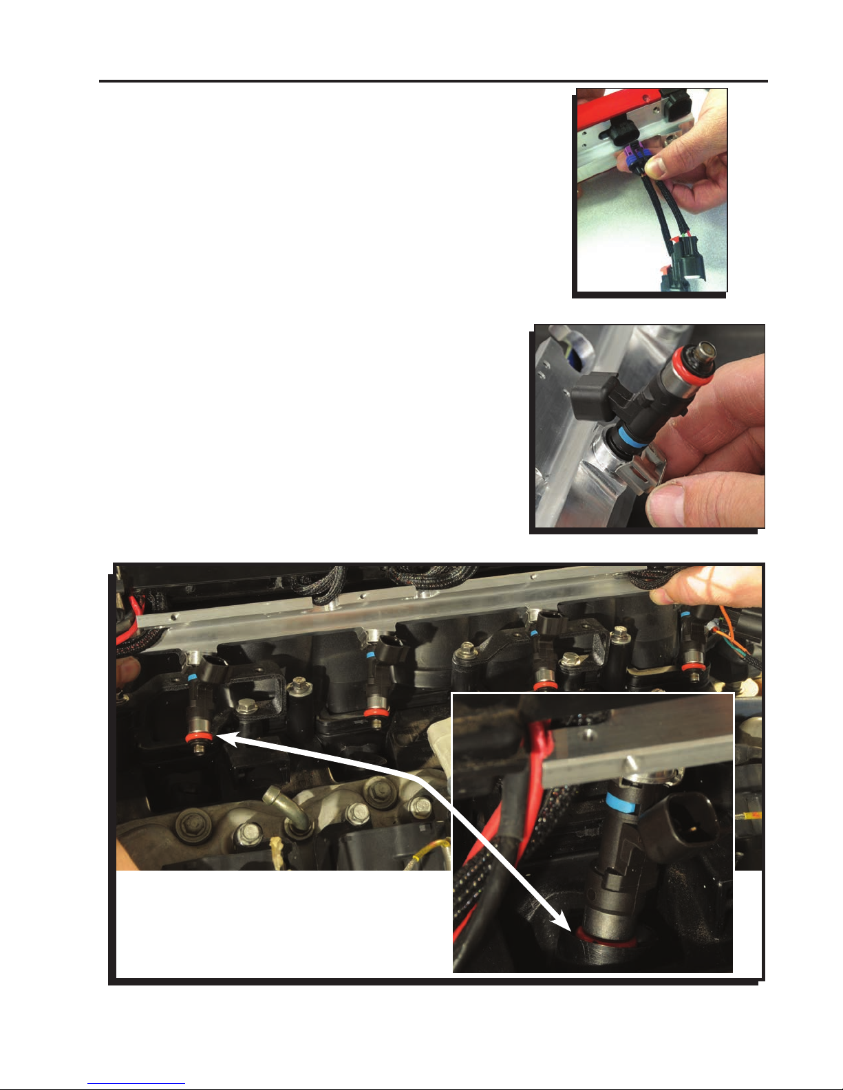
Each bank has OEM connectors that plug into the injectors, coils and specific
sensors of the engine. Each bank has a ground wire that must be connected to the
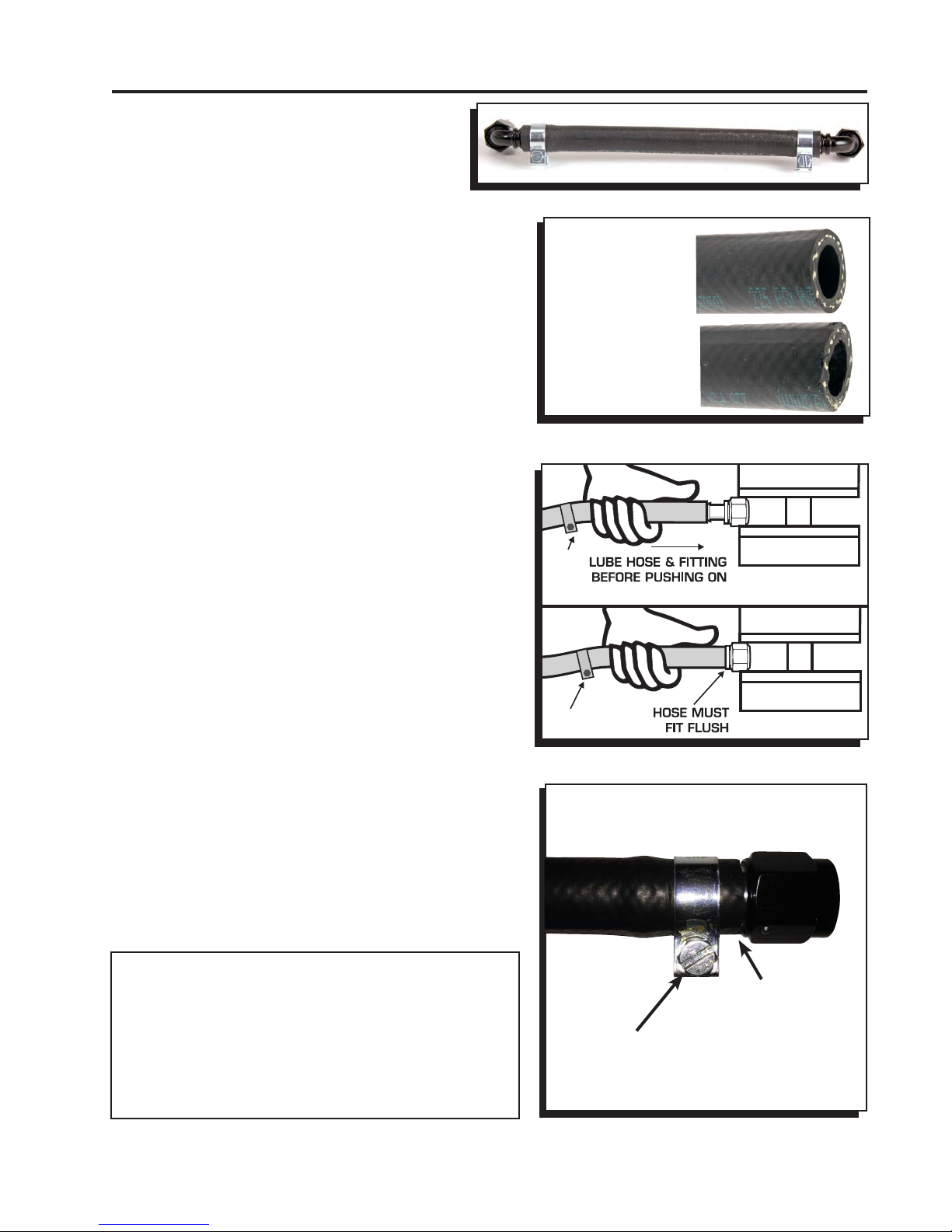
block. The fuel line inlets of the rail accept -6 AN and -8 AN fittings and internally
are equivalent to a -8 line (-6 AN fittings are supplied.)
Power Module: The Power Module of the Atomic LS is the communication hub of
the system and provides the high current fuel pump circuit and other input/outputs
for optional features. The unit has two ports for the MSD CAN system as well as
a wiring harness. There are connections for the WB02, the Handheld Monitor as
well as power and communication to the integrated fuel rails.
Programming: The Atomic EFI is a self-tuning fuel system that continuously adjusts after the basic
configuration is complete. There is no laptop programming. Based on the engine descriptors you input, the
Atomic will automatically create a base fuel map to get the engine running. Once running, the self- learning
system will continuously adjust those maps to obtain the desired air/fuel ratio. This feature ensures that
your engine will have the right fuel mixture at all times, no matter where you are driving.
Intake Manifolds: The Atomic LS EFI system is designed to fit most OE intake manifolds, as well as some
aftermarket intakes. There are different mounting brackets available for several of the key intake manifolds.
MSD offers two Installation Kits that are supplied with different injector connects and fuel rail brackets for
manifolds such as the LS1 or truck. They are described in the ‘Not Included’ list of parts above.
Fuel System: The Atomic LS system can be used with return or returnless EFI system. Review the Fuel
System Information section starting on page 3 for detailed information.
®
LS
CONTROLLER
24x 58x
POWER MODULE

INSTALLATION INSTRUCTIONS 3
Wide-Band 02 Sensor: A Wide-Band 02 sensor is supplied in the Atomic LS Master Kit. This sensor is
responsible for constantly monitoring the exhaust gases and relaying that information to the ECU where
adjustments are constantly made to the fuel delivery in order to meet the air/fuel targets. Only one sensor
is required. Page 5 outlines the sensor installation.
Crank Sensor: The LS engine platform has used two different crank position sensors through the years.
There is a 24-tooth wheel or a 58-tooth wheel on the crankshaft. The sensor has always been located
behind the starter. The 24-tooth sensor has a black connector whereas the 58-tooth sensor has a gray
connector. The Master Kits are supplied with connectors for both the 24x and 58x trigger sensors.
Cam Sensor: The Cam Sensor of LS engines has changed throughout the years. Not only it’s location,
but its wiring as well. Early models have the cam sensor located at the back of the block near the deck
surface. During 2005, as a running change, the location changed to the front of the block between the cam
and crankshaft. The Atomic LS system can function with both designs.
Throttle Body and Sensors: The Atomic LS requires a mechanically operated throttle body. In the future
Throttle by Wire applications will be covered. The Atomic has all of the OE connections for the throttle
body including Throttle Position (TPS) and Idle Air Control Solenoid (IAC).
Intake Air Temperature (IAT) Sensor: This sensor is supplied and it is recommended to install it in the
air intake duct before the throttle body. A 3/4" hole is required for the sensor.
Rev Limiter: There are two settings for a rev limiter; one through fuel, one through ignition. There is an
optional 2-Step Rev Limiter that can be used on the starting line for a low rpm limit. This is temporarily
activated through the Dark Blue wire of the Power Module to produce consistent launch rpm.
Aftermarket Auxiliary Settings: The Atomic LS system can support aftermarket performance parts or
power adders that carry a CARB Executive Order number. There are accessory controls to properly adjust
the timing and fuel delivery to meet the requirements of these auxiliary components. See the advanced
settings on pages 15-16.
FUEL SYSTEM REQUIREMENTS
The Atomic LS fuel injection system requires a high pressure fuel pump system. The fuel system is
not supplied due the large variety of applications incorporating the LS engine platform. Depending on
your engine combination, the Atomic LS requires a minimum of 58-62 psi to operate. When selecting
a pump, regulator and lines, be sure each component is designed to perform at high pressure. MSD
offers fuel pumps, hose and accessories to complete your installation. Following are some guidelines
in helping set up a fuel system for your Atomic as well as components available separately from MSD.
• The Atomic is capable of operating with a return or returnless style system. For best results with
either system, MSD strongly recommends an in-tank pump. Installing the fuel pump in the tank
results in quieter operation, less chance of cavitation and a reduction in pump temperature.
• When running a returnless fuel system (Pulse Width Modulated) the fuel pump must be mounted
in the tank. It is recommended to use an MSD Atomic Fuel Pump, PN 2925 or PN 2926.
• MSD supplies -6 AN clamp-style ttings for the fuel rails. These ttings must be used with MSD's
high pressure EFI hose. Refer to page 9 for installation.
• If mounting the pump in the tank is not an option, install the pump as close as possible to the tank.
Within 2-feet of sending unit is recommended.
• Do not use hard line when plumbing the fuel system. When using a PWM fuel system, pulsations
and harmonics could cause unstable fuel pressure resulting in pump cavitation or poor engine
performance.

4 INSTALLATION INSTRUCTIONS
FUEL
FILTER
FUEL TANK
FUEL
PUMP
IT IS RECOMMENDED TO MOUNT
THE FUEL PUMP IN THE TANK
WHENEVER POSSIBLE. IF IT MUST
BE MOUNTED EXTERNALLY
, MOUNT
THE PUMP WITHIN 2-FEET OF THE
FUEL TANK SENDING UNIT.
FUEL RAIL
(UNDER COVER)
FUEL RAIL
(UNDER COVER)
FUEL RAIL
(UNDER COVER)
-6 90°FITTING SUPPLIED
NOTE: IF RUNNING A RETURNLESS
FUEL SYSTEM, THE PUMP MUST
BE MOUNTED IN THE TANK.
MSD ADJUSTABLE
REGULATOR
Figure 1 Atomic LS Return Fuel System.
In-Tank Pumps
The MSD Atomic Fuel Pump (not supplied) can be used in the tank however it would require a sock, or
filter element, on the pickup side. It is important to note that the wiring used to run the pump will need
to meet requirements to be submersed in fuel. When wiring an in-tank pump, it is recommended to
use a wire that conforms to SAE specifications J1128 and J378. This wiring features a Thermoplastic
insulated wiring with polyvinyl chloride insulation for protection against gasoline, oil, and more.
In addition, different fuel line will be required internally if the pump is to be mounted in the tank. Fuel
line that meets SAE 30R10 specifications MUST be used. Failure to do so will cause severe damage
to your engine and/or fuel system.
WARNING: Improper installation or use of fuel system components can cause severe damage your
engine and/or fuel system that will not be covered by the manufacturer’s warranty.
Atomic Fuel Pump, PN 2925: This pump features 3/8” inlet and outlet. The pump will support
approximately 525 hp and is approved for in-tank use (no wiring or in-tank mounting hardware/
pickup element are supplied).
Fuel Pump Kit, PN 2920: This Kit is supplied with MSD’s PWM Fuel Pump, a pre and post-filter, 15-ft
of 3/8 fuel injection line and mounting hardware.
Fuel System Return Kit, PN 2922: If you plan on running a return line with your Atomic LS, this kit
provides another 15-ft of 3/8” injection line, an MSD Regulator and -6AN-to-hose fittings.
High Horsepower Fuel Kit, PN 2921: This pump will support the power demands of engines up to 650
horsepower. The pump features 3/8” inlet and outlet. The pump will support approximately 650
hp and is approved for in-tank use (no wiring or in-tank mounting hardware/sock are supplied).
WARNING: MSD's hose ttings are designed for use with MSD fuel hose only. Do not use the MSD
fuel hose with other fittings. Do not use MSD fittings with other fuel hose. Compatibility
issues may cause fuel leaks.

INSTALLATION INSTRUCTIONS 5
Figure 2 WBO2 Sensor Location.
POSITION
AT LEAST
10°
02 SENSOR
EXHAUST
COLLECTOR
WIDE BAND OXYGEN SENSOR INSTALLATION
The MSD Atomic EFI system requires a single Wide Band
Oxygen Sensor (WBO2) for operation. MSD suggests that
the bung for this sensor be installed prior to starting any
other part of the conversion process. By having the WBO2
in place first, there is a reduced chance of the vehicle
being immobilized for an extended time. The bung for
the WBO2 provided by MSD has a plug included so that
the vehicle can be driven between the time of exhaust
modification and installing the rest of the Atomic system,
if needed.
The WBO2 can be installed in downstream of either
exhaust bank. The sensor connects to the Power Module,
so install the sensor on the bank closest to where you
plan to mount the Module. The bung should be installed by a qualified exhaust technician and pressure
tested. Proper installation of the oxygen sensor is critical to the performance of the Atomic EFI. Improper
installation could lead to engine damage.
1. Locate the ideal spot to install the WBO2.
a. This location should be 2-4 inches after the exhaust collector. The sensor must be more than
18 inches forward of the exhaust tip. For applications where short or open headers are used,
install the WBO2 in the primary tube of the rear cylinder at least 8 inches away from the exhaust
port. The Atomic will not work on “Zoomie” style headers.
b. The WBO2 sensor should be at least 10˚ above horizontal to allow condensation runoff. Without
this angle the sensor is significantly more likely to sustain water damage (Figure 2).
c. Never place a WBO2 on the outside of a bend.
d. The WBO2 must be mounted in the exhaust prior to any catalytic converter, if applicable.
2. Drill a 7/8” hole in the exhaust where the WBO2 will go.
3. Weld in the supplied bung. Ensure the weld goes completely around the bung and is air tight.
4. Insert supplied plug in bung. Never run the vehicle with a WBO2 installed but not powered; it will
damage the sensor.
5. When completing the Atomic EFI installation, remove the plug and insert the WBO2 for use. MSD
suggests using a small amount of anti-seize on the threads.
Note: The Atomic EFI is extremely sensitive to air leaks in the exhaust system. Any air leak between
the engine and the WBO2 will cause the Atomic to have false readings, which can lead to poor
engine performance, misfires, and an inability to properly auto-tune. Extended running of the
Atomic EFI with an exhaust leak can result in detonation and severe engine damage. Improper
installation of the oxygen sensor, and any damage that may result from such an installation, is
not covered by the manufacturer’s warranty.

6 INSTALLATION INSTRUCTIONS
INSTALLING THE INTEGRATED FUEL/ECU RAILS
The integrated fuel/ECU rails are supplied with the covers installed. The rails are designed to install to OEM
intake manifolds and many aftermarket designs. To prepare the rails for installation, locate the four intake
manifold bolts supplied with the Atomic LS Master Kit, as well as the four mounting brackets.
It is important to note at this point, that you have the correct injectors for your application as well as O-ring
seals and the injector retainers. These components are not supplied in the master kit.
WARNING: Care must be used when installing the fuel injectors and rail assemblies.
The following steps will guide you
through the installation of the two fuel
rail assemblies.
1. The fuel rails are supplied with
the covers in place. Remove the
covers to prepare and install the
rail assemblies (Figure 3). Also,
determine which rail is which by
reviewing the sensor connectors
and location as shown in Figure 9
on page 8.
2. Figure 4 shows the location for the fuel
rail brackets. Remove the hardware
from the intake manifold and install
the brackets as shown using the
supplied longer intake bolts. Use
GM 1245383 thread sealant or
equivalent on the intake manifold
bolts. Note that the passenger rear
bracket requires a spacer (supplied)
as shown in Figure 4. Torque the new
intake bolts to 89 in-lbs.
NOTE: If installing the intake manifold
for the first time follow the
torque sequence in Figure
4. Torque in steps; 44 in-lbs
first, followed by 89 in-lbs.
It is recommended to hold
a straight edge against the
brackets to ensure alignment
while torquing. Figure 4 Fuel Rail Bracket Locations.
Figure 3 Removing Fuel Rail Covers.
REAR
REAR FRONT
BRACKET
NOTE: THE PASSENGER
SIDE REAR MOUNT
REQUIRES THE
SUPPLIED SPACER.
9 3 2 6 7
8
5 1 4 10
TORQUE SEQUENCE
STEP 1 - 44 LBS/INCH
STEP 2 - 89 LBS/INCH
FUEL RAILFUEL RAIL
COVER
LIFT THIS SIDE OF
COVER ENOUGH TO
CLEAR FUEL RAIL
FUEL RAILFUEL RAIL
COVER
PUSH COVER
FUEL RAILFUEL RAIL
COVER
LIFT COVER UP
DISENGAGE
FROM FUEL
RAIL
MUST USE THREAD SEALANT

INSTALLATION INSTRUCTIONS 7
3. Locate the four injector harness pigtails. These need
to be connected to the fuel rails (Figure 5).
4. With the brackets and injector pigtails installed on the
intake manifold, it is time to install the injectors to the
fuel rails. Apply a dab of engine oil to the o-ring seals
of the injectors. Insert the injector with its connector
facing towards the outside of engine into the fuel rail.
Install the injector retainer securely and check that it
is properly installed and sealed to the rail (Figure 6).
Continue with the other three injectors.
5. With the injectors installed, it is time to install the fuel
rail assembly to the engine. Position the rail assembly
over the intake manifold with the injectors aligning
with their mounting pockets on the intake (Figure 7).
6. With the injectors lined up, lightly press down on the
fuel rail using caution not to bind any of the injectors
or connectors. The fuel rail assembly should come
close to contacting the manifold brackets with very
little pressure. Use caution not to bind or tear any
injector O-rings.
Figure 6 Installing the Injectors.
Figure 7 Installing the Rail Assemblies.
ENSURE THAT THE
INJECTORS AND O-RINGS
SETTLE INTO THE POCKETS
WITH NO BINDING.
Figure 5 Connecting Injector Pigtail.

8 INSTALLATION INSTRUCTIONS
MAP
ECT
INJ8
INJ6
COILS
1357
CAN
CAN
ETC2/
V V T** ALT
COILS
2468
DRIVER
SIDE
PASSENGER
SIDE
INJ4
INJ2
INJ7
INJ5
IAC
ETC1/
TPS
INJ1
INJ3
OIL
PWR
CRANK
PWR
IAT
AC
IAC2*
FPS
F
G
H
FGH
D LPHI
D LPHI
GND
GND
CAM
PWR
TO
POWER
MODULE
**FOR DUAL THROTTLE
BODIES
**FOR ENGINES WITH
V V T OPTIONS
(NOT USED)
Figure 9 Fuel Rails and Connections.
Figure 8 Tighten the Fuel Rail Bolts.
7. Install the retaining bolts and washers to secure
the fuel/ECU rails to the mounting brackets. Move
between the retainers as they are tightened to ensure
even pressure (Figure 8).
8. Connect the injector wiring, coil packs and other
wiring.
9. Repeat (Figure 9) the procedure for the opposite
engine bank.
NOTE: PAGE 18 SHOWS PINOUTS FOR THE COIL CONNECTORS AND IAC.

INSTALLATION INSTRUCTIONS 9
Figure 10 Installing Fuel Hose to AN Fittings.
Fuel Inlet Fittings and Cross-Over Line: LS
engines require a cross-over fuel line to route
the fuel from one bank to the other. This is
typically done at the front of the engine. (Figure
10) Due to the variety of intake manifolds and
accessories, a cross-over line must be made
for each application
MSD supplies a length of fuel hose and two 90°
-6AN fittings to prepare a fuel crossover line. The fittings
are designed for use with the supplied hose and clamps.
Proper installation begins with a clean, square cut of
the hose. A hose cutting tool or a new razor blade are
recommended. When installing the hose, it is important
that the hose is pushed all the way to the backstop. The
clamp must be centered between the fitting rib and the
backstop before it is tightened.
1. Determine the length of hose needed. Mark the hose
and cut it using a hose cutter or new razor blade.
There should be minimal disturbance of the jacket and
braids. The cut plane should be perpendicular to the
hose axis (Figure 11).
2. Before installing the hose to the fitting, it is important to
anchor the fitting (Figure 12). Proper installation may
be difficult when holding the hose and fitting with your
hands. For best results, the hose should be installed
with minimal twisting or pausing.
3. Apply a light coating of oil to the rib on the fitting. Use
care not to get oil on the outside of the hose as it will
be impossible to maintain a grip on the hose.
4. With the fitting anchored securely, push the hose
over the fitting until it bottoms against the backstop.
Center the clamp between the rib and backstop before
tightening (Figure 13).
WARNING: The supplied MSD AN Fittings are
designed only for use with the supplied
fuel hose. We do not recommend
mixing fittings and hoses from different
manufacturers. Doing so may result in
fuel leaks and expose other dangerous
incompatibilities.
Figure 12 Installing Fuel Hose to the Push-Lock Fittings.
CLAMP
CLAMP
Figure 11 Severing the Hose Properly.
Figure 13 Installed Fitting and Clamp.
CORRECT CLEAN,
SQUARE CUT
INCORRECT
JAGGED, ROUGH
CUT
END OF HOSE IS FLUSH
WITH BACKSTOP
Properly Installed Clamp and Fitting
CLAMP IS CENTERED
BETWEEN RIB AND
BACKSTOP

10 INSTALLATION INSTRUCTIONS
®
LS
FUEL PUMP
GROUND
BATTERY 1*
BATTERY 2*
CAN
ONLY
HANDHELD
MONITOR
RED SLED POWER
RED FAN 1
DARK BLUE LAUNCH
BROWN/WHITE NITROUS
BROWN SPEED REF (-)
LT BLUE SPEED (+)
GRAY TACH
RED SW 12V
ORANGE FAN 2
LT GREEN MIL GROUND
IP
VM
H-
H+
IA
UN
RED
YELLOW
BLK/WHT
BLK/RED
GREEN
BLACK
TO PASSENGER
FUEL RAIL
CAN TO
PASSENGER
FUEL RAIL
CONTROLLER
MONITOR
CONNECTOR
ONLY
* BATTERY 1 AND 2
MUST BOTH BE
CONNECTED
ORANGE
BLACK
HEAVY RED
HEAVY RED
Figure 15 Power Module Wiring Diagram.
POWER MODULE INSTALLATION
The Power Module of the Atomic EFI system handles
high current circuits such as the fuel pump and WBO2.
The unit has two ports for the MSD CAN system as
well as a wiring harness. The CAN ports will provide
communication between the Power Module, the
passenger side fuel/ECU rail and the Handheld Monitor.
It is important to select a proper mounting location for the
Power Module. The unit can be mounted in the interior
or the engine compartment as long as it is away from
direct heat sources. It is not recommended to mount the
unit in an enclosed area, such as the glovebox. When
a suitable location is found, make sure all wires reach
their connections. Also be sure that the CAN port can
be accessed for use with the Handheld Monitor.
Use the Power Module as a template and mark the location of the holes. Use a size #20 drill bit to
prepare for the supplied self tapping screws. Install the supplied rubber grommets (Figure 14).
POWER MODULE
WIRING
There are a number of
electrical connections on
the Power Module that
are required for proper
operation (Figure 15). Other
wires, such as the nitrous
input, 2-step rev control or
electric fan controls, only
need to be connected if
their optional functions are
being used. In the chart
below, wires marked “REQ”
must be connected for the
system to operate while
those marked “OPT” are
optional depending on
the features being used.
For the installation it is
recommended to connect
only the required wires.
Figure 14 Power Module Wiring Diagram.
®
LS
CONTROLLER

INSTALLATION INSTRUCTIONS 11
Power Module
Pin
1
2
3
4
A
B
C
D
E
F
G
H
J
K
L
M
N
P
R
S
Color
Red
Black
Orange
Red
Red
Blue
Bro/Wht
Brown
Lt Blue
Gray
Red
Orange
Red
Red
Yellow
Blk/Wht
Blk/Red
Green
Black
Lt Green
Use
REQ
REQ
REQ
REQ
OPT
OPT
OPT
OPT
OPT
OPT
REQ
OPT
REQ
REQ
REQ
REQ
REQ
REQ
REQ
OPT
Function
Battery 1, Connect to Positive Battery terminal.
Ground, Connect to solid, clean engine ground.
Pump, Connect to Fuel Pump Positive terminal.
Battery 2, Connect to Battery Positive terminal.
Fan 1, Supplies ground to activate Fan 1
Launch, Connect to 12 volts to activate 2-step RPM limit.
Auxiliary Timing and Fuel, When supplied with 12 volts, timing
will be retarded and the air/fuel ratio will be corrected to the
target auxiliary setting.
Speed Ref.
Speed Signal
Tach, Supplies 12V square wave signal
Switched 12V, Connect to ignition switch
Fan 2, Supplies ground to activate Fan 2 at desired temperature.
Supplies power to the Fuel Rail
IP
VM
H-
H+
IA
UN
WBO2
MIL Ground
CONNECTOR
Deutsch
4-Way
CONNECTOR
GT Series 16 Way
STOP HERE
REVIEW YOUR INSTALLATION
It is recommended to review your installation at this point. The 02 Sensor should be installed and connected as
well as the Power Module and corresponding wiring. Confirm that all of the rail wiring connections are complete
including the injectors and sensors. Ensure all fuel lines and fittings are tight and secure from any heat sources or
sharp edges. The next section will require powering the Atomic LS to go through the Initial Setup menus and the
fuel pump will run. DO NOT START THE ENGINE AT THIS TIME!
It is recommended to connect a Malfunction
Indicator Lamp (MIL) to your dash. A simple
bulb is required with switched 12 volts on
one side and this Light Green wire on the
ground side. If there is a malfunction in the
system, ground will be supplied through this
wire to illuminate the lamp.
(2)
(1)
Wire
Black wires w/ring lugs
Orange flying Lead
Function
Coil ground wires that should be attached to the cylinder
heads.
A/C kick up wire. This should be wired to a source that
gets 12V then the A/C compressor clutch is engaged. This
will open the IAC up slightly and will also kick on fan #1
regardless of coolant temperature.
Sleds

12 INSTALLATION INSTRUCTIONS
WARNING: DO NOT ATTEMPT TO START THE ENGINE. Before turning the ignition key to the
ON position, confirm all fuel line connections are tight and all electrical connections
are correct. After confirming all electrical connections and fuel lines, turn the ignition
key to the ON position. Check every hose and fitting connection for any signs of fuel
leaks. The Handheld screen should illuminate and display the Main Menu.
Atomic LS Gauges
Atomic LS Dash
Main Menu
Figure 17 Monitor Main Menu
PROGRAMMING
The Handheld Monitor plugs into the Power Module via the
CAN connection. It can be removed once the initial setup is
complete, or can remain connected for use of features such
as the dash or digital gauge displays. The Handheld Monitor
features a joystick to scroll through the settings. Scroll up and
down to the setting and push the joy stick to the right to select
the options. When the selection is made, either push in, or
go back (push to the left) to save/confirm settings changes.
MAIN MENU
Six selections will come up the Monitor under the Main Menu.
If this is the first time powering up the Atomic LS, select Initial
Setup (Figure 17).
Atomic LS Dash: This selection allows you to view a variety
of engine functions in real time when the engine is
running. Refer to page 19 for a complete description
of each parameter in the Atomic Dash.
Atomic LS Gauges: This setting puts five important values
in gauge form to ease viewing the data. This includes
engine rpm, oil pressure, engine coolant temperature,
speed (when connected), battery voltage, and air/fuel
ratio.
Initial Setup: These are values that are required to start the
engine.
Advanced Setup: Optional settings for features and optimized
drivability settings.
Diagnostics: This screen will help you troubleshoot and
identify potential issues.
Display Setup: Provides adjustments for the appearance of
the monitor screen. See page 18 for more information.
ENGINE IDENTIFICATION INFORMATION
GM has produced a number of different LS based engine
platforms. When setting up your Atomic LS system, it is helpful
to know the model engine you have. If you don’t know what
engine you have, locate the casting number on the back of the
block, below the driver's side cylinder head (Figure 16). That
number will assist in determining what engine you have. If
you still have no idea of your engine’s origin, you can select
a base calibration from the menu to get the engine started.
Figure 16 Casting

INSTALLATION INSTRUCTIONS 13
INITIAL SETUP PROGRAMMING
Scroll down to Initial Setup and push the joystick to the right.
The following parameters must be programmed.
Engine Type: This value determines the engine platform (Figure
18). There are over 26 engine combinations to select
from. This setting is important as once an engine type
is programmed, other settings will default to the OEM
components that were supplied on that engine.For
example, if LS1 is selected, the coil, injector and MAP
sensor will automatically set to the OEM components.
Engine Size: Once the engine type has been selected, the
stock cubic inches will automatically be set. If the engine
has been modified with a different stroke or bore, select
and input the size. The range is from 100-800 cubic
inches (Figure 18).
Camshaft Type: There are three cam selections to choose;
Street/Stock, Mild and Performance. Note that if the
lobe separation angle (LSA) is less than 108°, it is
recommended to input the next larger cam. Cams with
over 250° are not recommended for use with the Atomic
LS system (Figure 18).
Coils
Camshaft Type
Handheld Main Menu
Engine Type
Engine Size
Figure 18
CAM
Street Stock Less than 210°
Mild 211° - 230°
Performance 231° - 250°
DURATION AT .050"
Coils: Once the engine type is selected, the OEM coil pack
will be automatically loaded in the default calibration
file. If a different coil or an MSD LS Coil pack is used,
change the setting to the correct coil type (Figure 18).
Note: There is a setting in Display Setup labeled User Mode.
When User Mode is changed from Basic to Advanced,
the coil selection menu will open up to all the coil
combinations preprogrammed into the Atomic LS
system.

14 INSTALLATION INSTRUCTIONS
Fuel Injector: Once the engine type is selected above, the
OEM style injector will be automatically loaded in the
default calibration file. If a different injector is used,
change the setting to the correct injector. Most LS
based injectors have the part number stamped on
them (Figure 19).
Note: There is a setting in Display Setup labeled User
Mode. When User Mode is changed from Basic
to Advanced, the fuel injector selection menu
will open up to all the fuel injector combinations
preprogrammed into the Atomic LS system.
This setting will also unlock a setting called
User Defined. User Defined allows the injector
flow rate to manually be entered by selecting
Set Calibration (Figure 19).
MAP Sensor: Once the engine type is selected above, the
OEM MAP Sensor will be automatically selected.
(Figure 19).
Note: There is a setting in Display Setup labeled User
Mode. When User Mode is changed from Basic
to Advanced, the MAP sensor selection menu
will open up to all the MAP Sensor combinations
preprogrammed into the Atomic LS system.
This setting will also unlock a setting called
User Defined. User Defined allows the Slope
and offset to manually be entered by selecting
Set Calibration.
Fuel Pump Type: There are three selections for the fuel pump
system. Select the system in use with the Atomic LS
system (Figure 19).
•Pulse Width Modulated: This selection is used
only when running a returnless fuel system with NO
regulator.
•Non-PWM with Regulator: This selection is used
when running a return style system with a regulator.
•PWM with Regulator: This selection is used when
running a return style system with a regulator. It will
run the pump at 50% duty cycle at idle producing
quieter pump operation and will increase the duty
cycle to 100% as the throttle and injector load
increase.
Note: It is recommended to use Non-PWM with a regulator
when setting fuel pressure as the PWM setting may
decrease fuel pressure slightly at idle.
Fuel Injector Type
Fuel Injector
Injector Lbs/Hr
Figure 19
Map Sensor
Fuel Pump Type

INSTALLATION INSTRUCTIONS 15
Idle RPM Target: Select the rpm that the engine should idle
at. The rpm range is adjustable in 25 rpm increments
(Figure 20).
Note: Running too high of an idle speed in an automatic
transmission equipped vehicle with a stock torque
converter can cause idle issues in gear. The IAC counts
should be set at approximately 10-30 in neutral with the
engine warmed up, running and the A/C off. This is
done by opening or closing the throttle blade. It must
be set after the commanded idle is entered here.
Rev Limit: The rev limiter can be set as a fuel cut-off or ignition
cut-off limiter. The default setting is as a fuel cut-off
limiter set at 6500 RPM. The programming range for
both rev-limiters is 3000 RPM-10,000 RPM (Figure 20).
The ignition cut should only be used on race vehicles
with a very free flowing exhaust. DO NOT use with
catalytic converters or severe damage may result!
Once all of the settings in the Initial Setup menu are selected,
the Atomic has enough information to start and run the engine.
It is recommended to scroll through the advanced settings to
program selections that may be useful after the initial start up
(such as the cooling fan activation temperatures).
ADVANCED SETUP
The Advanced Setup features are optional as the Initial Setup
menu provides the Atomic EFI with the values needed to run
the engine. Features in the Advanced Menu are designed to
deliver additional features and advanced tuning functions to
further enhance the drivability and overall performance of the
engine.
Fans: This setting sets the temperatures to activate two electric
fans. Each circuit will be activated by supplying ground
through the Red (Pin A) and Orange (Pin H) wires of
the GT-Series 16 pin harness from the Power Module. A
relay is required for both circuits since those wires are a
low current ground. The fans will activate at the desired
temperature and will remain on until the temperature
falls below 10° of the setting. Settings are 100°-300°F
(Figure 20). Figure 20
Idle RPM Target
Rev Limit
Advanced Setup
Fans

16 INSTALLATION INSTRUCTIONS
A/F Targets: The Atomic LS provides an option to set an air/fuel
target for Idle, Part Throttle, Wide Open (WOT), Boost and
an Auxiliary setting. The Atomic will use its self-learning
technology to adjust the fuel delivery to meet the target air/
fuel ratio. The values are adjusted in 0.1 increments and
range from rich at 10:1 to dead lean at 16:1. The ideal air/fuel
ratio for cruising is called stoichiometric and is commonly
referred as a 14.7:1 air/fuel ratio.
Boost: The Atomic will switch to the commanded boost
A/F ratio once the manifold pressure reaches
110Kpa (approximately 16 psia - 32.5in/Hg)
(Figure 21).
Ignition Timing: The Atomic provides a base timing table for each
engine application. These values can also be modified to
compensate for CARB approved accessories. Each setting
is adjustable +/-10°. Note that the values programmed
are set for stock engines using 91 octane fuel. For lower
octane fuels it is recommended to retard the timing 5° as
a starting point. Timing can be retarded up to 20° in 0.1°
increments. Note that in order to alter the timing for auxiliary
use, the Auxiliary Selection in the Advanced menu MUST be
programmed to ENABLE. When 12 volts are applied to the
Brown/White wire (Pin C), the timing will retard (Figure 21).
TPS Enrichment: To assist in throttle transitions the Atomic EFI has
a feature to increase fuel delivery by a prescribed percentage
any time there is an increase in throttle position. If needed,
make small changes in no more than 5% increments without
further testing. Most engines will find 25% sufficient. Most
applications will accept 15%-35% enrichment. Adjustable
from 0-100% in 1% increments (Figure 21).
MAP Enrichment: To assist in manifold pressure transitions the
Atomic EFI offers a MAP enrichment feature. This function
adds fuel based on MAP transitions while moving the throttle.
Large cam vehicles with low vacuum generally required a
slightly smaller number while stock/small camshaft vehicles
with a high vacuum may require more. If needed make small
changes of no more than 5% increments without further
testing, 25% is sufficient for most engines but between 15-
35% is normal. Typically, the higher the vacuum the higher
the percentage needed. Adjustable from 0-100% in 1%
increments (Figure 21).
2-Step: This setting will rev-limit the engine at the programmed RPM
when the Blue wire is activated with 12V. The 2-Step setting
is used in drag racing applications to help launch the car at
a consistant RPM. The blue wire is normally connected to a
clutch switch or a brake switch. The default setting is 10,000
RPM and can be adjusted from 1000 RPM to 7500 RPM in
25 RPM increments (Figure 21). The ignition cut should only
be used on race vehicles with a very free flowing exhaust.
DO NOT use with catalytic converters or severe damage
may result!
TPS Enrichment
Igniton Timing
A/F Targets
Figure 21
MAP Enrichment Setting
2-Step RPM Limit

INSTALLATION INSTRUCTIONS 17
Racepak Dash Option
Speed Reference Setting
Enable or Disable Nitrous
Figure 22
Auxiliary: When switched to Enabled, this setting will ready
the Auxiliary timing retard and Air/Fuel Ratio settings
to compensate for approved accessories when the
Brown/White wire is connected to 12v. The default
setting is DISABLED (Figure 22).
Calibrate Speed: If there is speed output on the transmission,
a reference signal can be delivered to the Atomic
LS. On manual transmission equipped vehicles, the
Calibrate Speed option improves drivability when
transitioning from high RPM conditions to an idle
(such as comming off of a hill / between moving and
coming to a complete stop). The Power Module has
a Brown (Pin D) wire and a Light Blue (Pin E) wire.
These wires connect to a magnetic pickup monitoring
driveshaft speed with a collar mounted on a yoke. To
program the calibration, drive to 40mph on an open
road to maintain speed. Once at 40mph, select YES
on the handheld. This will calibrate the speed input.
This option will also enable a speedometer reading in
the handheld Atomic LS Dash (Figure 22).
Note: Use of a minimum four magnet collar is
recommended with this option.
Racepak Dash: This setting allows the Atomic LS kit to
interface with a Racepak dash such an IQ3. Disable
is the default setting. Racepak offers an optional V-net
sensor to connect their dash to the MSD Can-Bus
connector (Figure 22).
Advanced Setup

18 INSTALLATION INSTRUCTIONS
HANDHELD DISPLAY OPTIONS
Display Setup: The display Setup controls the look of the
handheld unit and the Firmware version. The Atomic
LS can be reset to factory default in this section as well
(Figure 23).
LCD Contrast: Adjust the contrast on the LCD screen if it is
hard to see the display. Contrast is adjusted using the
joystick to go up or down in five percentage increments.
Backlight Level: The brightness of the screen is determined
by this setting. The Backlight Level may need to be
adjusted depending on outside light levels. Brightness
is adjusted using the joystick to go up or down in five
percentage increments (Figure 23).
Display Units: The Atomic can display items in either English (cubic inches, Fahrenheit) or Metric
(liters, Celsius). Set Atomic Defaults: Use this feature to reset the Atomic EFI. Selecting “YES”
on this screen will take all setting, including fuel maps, back to the factory defaults. This can
be done when installing the Atomic on a different engine, or for troubleshooting reasons
(Figure 23).
User Mode: This setting can be changed from Basic to Advanced. When the User Mode setting is
changed to Advance the fuel injector selection menu, coil selection menu, and the MAP sensor
menu will open up to all the combinations preprogrammed into the Atomic LS system. The
fuel injector flow rate and MAP sensor Slope and Offset can be manually entered by selecting
user defined in the selection menu (Figure 23).
Set Atomic Defaults: This setting resets all the programming parameters to the default settings out
of the box (Figure 23).
Firmware Versions: The Atomic Firmware version can be found in this section (Figure 23).
PRE-START CHECK LIST
Before attempting to start the motor, run through the pre-start check list to ensure a safe and successful
start.
• Double-check all wiring
• Power and ground leads are connected directly to the battery.
• Red (Pin G) should be connected to a 12v ignition source that is hot in the RUN and START positions
of the key cycle.
• All wiring, modules, and fuel components are mounted away from heat sources such as exhaust
and pinch points.
• Wideband O2 sensor is installed and plugged into the Power Module
• There are no exhaust leaks.
• The throttle linkage is connected and moves freely with no binding.
• The initial programming has been set in the handheld menu.
• Key on the ignition a few times to prime the fuel pump. The fuel pressure may need to be adjusted
to 58-60psi. Fuel pressure can be monitored in the Atomic Dash section of the handheld menu.
• With the fuel system under pressure from priming the system, check for leaks or fuel spraying. Do
not attempt to start the engine if fuel leaks are present.
• Monitor Engine RPM in the Atomic Dash in the handheld unit as the engine is cranked over to
ensure the crank sensor is providing an RPM signal.
Figure 23 Monitor Display Selections.

INSTALLATION INSTRUCTIONS 19
The Atomic LS Dash is a live display when the engine is running.
This is a brief description of each parameter in the Atomic LS Dash.
ATOMIC LS DASH:
Tach Displays engine RPM.
Speed Displays Speed if speed if speed sensor is equipped and calibrated.
ECT Displays coolant temperature.
IAT Displays intake air temperature.
TPS Displays throttle position sensor percentage.
BARO Displays barometric pressure
MAP Displays manifold absolute pressure
FUEL PRESS Displays fuel pressure.
OIL PRESS Displays oil pressure.
BAT VOLTS Displays battery voltage.
A/F RATIO Displays air/fuel ratio.
INJ DUTY Displays injector duty cycle.
IGN TIMING Displays ignition timing.
IAC POS Displays idle air control motor position.
THROTTLE Displays throttle condition closed/part/WOT (Wide Open Throttle)
CLOSED LOOP Displays closed loop on or off.
LEARNING Displays Atomic LS learning on or off.
FAN 1 Displays Fan 1 on or off.
FAN 2 Displays Fan 2 on or off.
DECEL FUEL Displays if decel fuel is active
IDLE COND Displays if engine is in an idle condition
FLOOD CLEAR Displays if throttle is in a flood clear condition (no fuel will go in)
REV LIMIT Displays if the rev limiter is active
TWO STEP Displays if the two step is active.
AUXILIARY Displays if the Auxiliary timing/AFR is active.

20 INSTALLATION INSTRUCTIONS
CODE NAME
TPS
MAP
IAT
ECT
BATT
INJ DC
FUEL
PRESSURE
WBO2
FP CAV
MAP SELECT
BARO
WHAT IT MEANS
There is no reading for the Throttle Posi-
tion Sensor.
There is no reading for the Manifold Ab-
solute Pressure Sensor.
There is no reading for the Inlet Air Tem-
perature Sensor. The ECU will default
to 275°F when shorted or -40°F when
open.
There is no reading for the Engine Cool-
ant Temperature Sensor. The ECU will
default to 275°F when shorted or -40°F
when open.
The Atomic is receiving the wrong volt-
age. The unit is measuring either less
than 9 volts or greater than 16 volts.
Excessive Injector Duty Cycle
There is no reading for the Fuel Pressure
Sensor.
A. "NOT CONNECTED" indicates that no
sensor is detected.
B. "ERROR" indicates that the sensor
has failed.
This code will set if there is an issue with
Fuel Pump Cavitation (similar to vapor
lock). It can only set when running a
returnless fuel system. This may occur
when the commanded fuel pressure
(from the ECU) is different than the fuel
pressure (at the sending unit).
ECU compares the MAP reading with
the Baro reading on key up. If these are
different by more than 5kPa, the code
is activated.
The Baro sensor voltage is out of range,
and the ECU has defaulted to the last
known good Baro value.
PROBABLE CORRECTION(S)
The sensor may be at fault. Check wiring and/or replace sensor.
The sensor maybe at fault. Check wiring and/or replace sensor.
Faulty sensor; loose or no connection. Check wiring and/or re-
place sensor.
Faulty sensor; loose or no connection. Check wiring and/or re-
place sensor.
Check the battery connection from the Power Module to the
battery. Ensure that the battery and alternator are working cor-
rectly.
If you are running a returnless fuel system, your engine's needs
may exceed the Atomic's maximum capabilities. If you are run-
ning a return system check to see that you are maintaining the
recommended fuel pressure. If you have adequate fuel pres-
sure the engine's needs may exceed the Atomic's system ca-
pabilities.
Faulty sensor; loose or no connection. Check wiring and/or re-
place sensor.
A. Check to see that the sensor is securely plugged into the
system. Inspect wiring if it is plugged into the system.
B. The sensor will need to be replaced.
Note that 'warming up' is normal during start-up for the rst 20
seconds.
Check the fuel system and etermine that it meets the requirements
to run a returnless (PWM) system. Check the filters, the sock in
the tank, and inspect the lines for any kinks or pinches that
would affect the fuel flow and pressure of the system. If the code
continues, the fuel system may need to be converted to an in-tank
fuel pump and/or regulated (return) fuel system.
Double check your MAP selection and make sure that you
selected the correct P/N of sensor. It could also mean a problem
with the Baro or MAP sensor itself (see above codes).
Turn the ignition off. Wait 10 seconds, and turn the ignition
back on. If the code remains, call customer service. Unless the
vehicle has been through a large change in altitude since the
last ignition on/off cycle (towed somewhere), everything will
function normally.
DIAGNOSTICS
There is a self-diagnosing system built into the Atomic EFI. Each
covered parameter can show a status in one of three ways
(Figure 24).
• “OK”: the parameter is functioning normally.
• “Error C”: there is currently an error occurring.
• “Error H”: A previous error that has been reset since it did
not reoccur within the last ten ignition cycles.
The following chart gives the most likely solution(s) to each
possible error.
CLEARING HISTORY ERRORS
Figure 24
Table of contents
Other MSD Laboratory Equipment manuals