•
Service Manual
>
Safety
Precautions
The following precautions should be observed while handling the system:
• Place the system on a flat and stable surface.
• Do not place the system in environments subject to mist, smoke, vibration, excessive
dust, salty or greasy air, or other corrosive gases and fumes.
• Do not drop or jolt the system.
• Do not bump or knock the LCD screen
as
it is fragile and could break.
• Do not use another power adapter other than the one enclosed with the system.
• Disconnect the AC/DC adapter before performing any installation procedures on the
system.
• Do not perform any maintenance with wet hands.
• Prevent foreign substances, such as water, other liquids or chemicals, from entering
the system while performing installation procedures on the system.
• Use a grounded wrist strap before handling system components such as CPU,
Memory,
HOD,
mini PCI-E card, etc.
• Place system components on a grounded antistatic pad or
on
the bed that came
with the components whenever the components are separated from the system.
• If there are any difficulties installing hardware devices, please contact MSI for further
information.
>
Other
Notice
• The peripheral devices contained herein may vary depending on your actual system
configuration.
• Third-party trademarks and names are the properties
of
their respective owners.
• The information contained herein relevant to software and hardware are for refer-
ence only and
in
accordance with actual system configuration. All information is
subject to change without notice.
>
Upgrade
and
Warranty
Please note that certain components preinstalled
in
the product users purchased may
be upgradable or replaceable by user's request.
To
learn more about upgrade limita-
tion, please refer to the specification
in
the User's Manual. For any further information
about the product users purchased, please contact the local dealer. It is strongly rec-
ommended that you contact the authorized dealer or service center for any upgrade or
replace service.
>
Acquisition
of
Replaceable
Parts
Please be noticed that the acquisition of replaceable parts (or compatible ones)
of
the product users purchased in certain countries or territories may be fulfilled by the
manufacturer within 2 years at most since the product has been discontinued, depend-
ing on the official regulations declared at the time. Please contact the manufacturer
via https://www.msi.com/support/ for the detailed information about the acquisition
of
spare parts.
Trident Series
>
Arrow
Used in
This
Manual
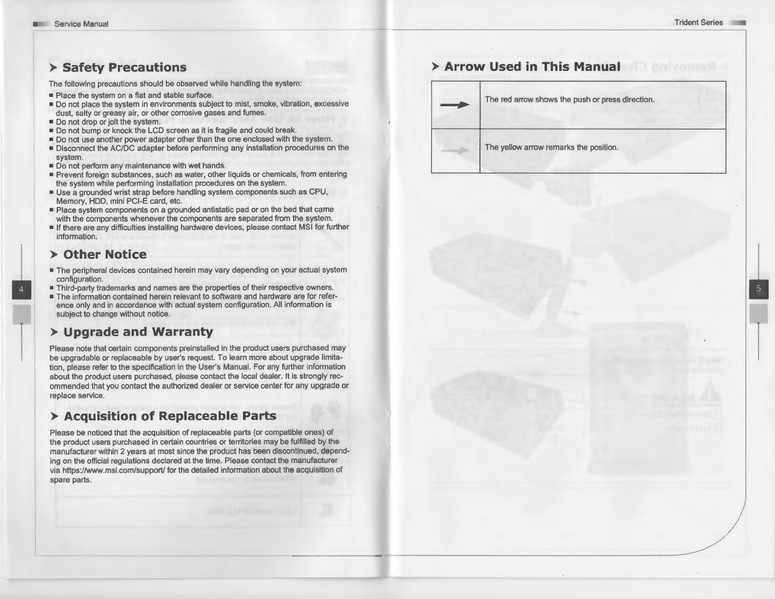
~
The red arrow shows the push or press direction.
The yellow arrow remarks the position.
•