MSI A68HM User manual

1
< 1> Contents
Contents
Safety Information...........................................................................................2
Specifications...................................................................................................3
Rear I/O Panel ................................................................................................. 6
LAN Port LED Status Table................................................................................6
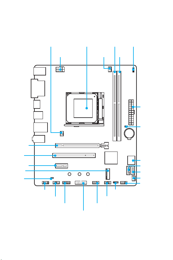
Overview of Components ................................................................................ 7
CPU Socket.........................................................................................................8
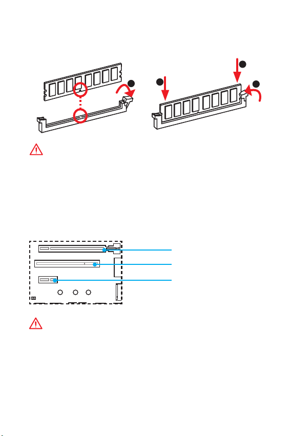
DIMM Slots .........................................................................................................9
PCI_E1~E2, PCI1: PCIe/ PCI Expansion Slot......................................................9
SATA1~4: SATA 6Gb/s Connectors...................................................................10
JFP1, JFP2: Front Panel Connectors...............................................................10
M2_1: M.2 Slot..................................................................................................11
JPWR1~2: Power Connectors..........................................................................12
JTPM1: TPM Module Connector.......................................................................12
JUSB1~2: USB 2.0 Connectors ........................................................................13
JUSB3: USB 3.1 Gen1 Connector.....................................................................13
JAUD1: Front Audio Connector ........................................................................14
JCOM1: Serial Port Connector.........................................................................14
CPU_FAN1, SYS_FAN1~2: Fan Connectors .....................................................14
JCI1: Chassis Intrusion Connector ..................................................................15
JBAT1: Clear CMOS (Reset BIOS) Jumper.......................................................15
EZ Debug LED: Debug LED indicators............................................................15
BIOS Setup.....................................................................................................16
Entering BIOS Setup.........................................................................................16
Resetting BIOS .................................................................................................17
Updating BIOS ..................................................................................................17
Software Description..................................................................................... 18
Installing Windows®7/ 8.1/ 10.........................................................................18
Installing Drivers..............................................................................................18
Installing Utilities.............................................................................................18
Thank you for purchasing the MSI®A68HM GAMING
motherboard. This User Guide gives information about board
layout, component overview and BIOS setup.

2Safety Information
Safety Information
yThe components included in this package are prone to damage from electrostatic
discharge (ESD). Please adhere to the following instructions to ensure successful
computer assembly.
yEnsure that all components are securely connected. Loose connections may cause
the computer to not recognize a component or fail to start.
yHold the motherboard by the edges to avoid touching sensitive components.
yIt is recommended to wear an electrostatic discharge (ESD) wrist strap when
handling the motherboard to prevent electrostatic damage. If an ESD wrist strap
is not available, discharge yourself of static electricity by touching another metal
object before handling the motherboard.
yStore the motherboard in an electrostatic shielding container or on an anti-static
pad whenever the motherboard is not installed.
yBefore turning on the computer, ensure that there are no loose screws or metal
components on the motherboard or anywhere within the computer case.
yDo not boot the computer before installation is completed. This could cause
permanent damage to the components as well as injury to the user.
yIf you need help during any installation step, please consult a certified computer
technician.
yAlways turn off the power supply and unplug the power cord from the power outlet
before installing or removing any computer component.
yKeep this user guide for future reference.
yKeep this motherboard away from humidity.
yMake sure that your electrical outlet provides the same voltage as is indicated on
the PSU, before connecting the PSU to the electrical outlet.
yPlace the power cord such a way that people can not step on it. Do not place
anything over the power cord.
yAll cautions and warnings on the motherboard should be noted.
yIf any of the following situations arises, get the motherboard checked by service
personnel:
Liquid has penetrated into the computer.
The motherboard has been exposed to moisture.
The motherboard does not work well or you can not get it work according to user
guide.
The motherboard has been dropped and damaged.
The motherboard has obvious sign of breakage.
yDo not leave this motherboard in an environment above 60C (140F), it may
damage the motherboard.

3
Safety Information Specifications
Specifications
CPU
Supports AMD®A-series/ Athlon™processors for Socket FM2/
FM2+*
* If you install the Carrizo processor in the motherboard,
please note that you have to update the chipset drivers in
advance on www.msi.com .
Chipset AMD®A68H Chipset
Memory
y2x DDR3 memory slots, support up to 32GB
Supports DDR3 2400(OC)/ 2133(OC)/ 1866/ 1600/ 1333
MHz*
yDual channel memory architecture
ySupports non-ECC, un-buffered memory
ySupports AMD®Memory Profile (AMP)
ySupports Intel®Extreme Memory Profile (XMP)
* Please refer to www.msi.com for more information on
compatible memory.
Expansion Slots
y1x PCIe 3.0 x16 slot
y1x PCIe 2.0 x1 slot
y1x PCI slot
Onboard Graphics
y1x VGA port, supports a maximum resolution of
1920x1200@60Hz
y1x DVI-D port, supports a maximum resolution of
2560x1600@60Hz and 1920x1200@60Hz
y1x HDMI port, supports a maximum resolution of
4096x2160@24Hz*, 3840x2160@30Hz*, 1920x1200@120Hz
and 1920x1200@60Hz
* Supported by FM2+ processors
Audio yRealtek®ALC887 Codec
y7.1-Channel High Definition Audio
LAN 1x Realtek®RTL8111H Gigabit LAN controller
Storage
AMD®A68H Chipset
y4x SATA 6Gb/s ports
Supports RAID 0, RAID 1 and RAID 10
y1xM.2 slot (Key M)
Supports up to PCIe 2.0 x4 and SATA 6Gb/s*
Supports 2242/ 2260/ 2280 storage devices
* The SATA1 will be unavailable when installing M.2 SATA
device in M.2 slot.
Continued on next page

4Specifications
Continued from previous page
USB
yAMD®A68H Chipset
2x USB 3.1 Gen1 (SuperSpeed USB) ports available through
the internal USB connector
8x USB 2.0 (High-speed USB) ports (4 ports on the
back panel, 4 ports available through the internal USB
connectors)
yAsmedia 1143 Chip
1x USB 3.1 Gen2 (SuperSpeed USB 10Gbps) port on the
back panel
1x USB 3.1 Gen2 (Super Speed USB 10Gbps) Type-C port on
the back panel
Back Panel
Connectors
y1x PS/2 mouse & keyboard combo port
y4x USB 2.0 ports
y1x VGA port
y1x DVI-D port
y1x HDMI port
y1x USB 3.1 Gen2 Type-A port
y1x USB 3.1 Gen2 Type-C port
y1x LAN (RJ45) port
y3x audio jacks
Internal
Connectors
y1x 24-pin ATX main power connector
y1x 8-pin ATX 12V power connector
y4x SATA 6Gb/s connectors
y1x M.2 slot
y2x USB 2.0 connectors (supports additional 4 USB 2.0 ports)
y1x USB 3.1 Gen1 connector (supports additional 2 USB 3.1
Gen1 ports)
y1x 4-pin CPU fan connector
y2x 4-pin system fan connectors
y1x Front panel audio connector
y2x Front panel connectors
y1x Serial Port connector
y1x TPM connector
y1x Chassis Intrusion connector
y1x Clear CMOS jumper
I/O Controller FINTEK F71878 Controller Chip
Hardware
Monitor
yCPU/System temperature detection
yCPU/System fan speed detection
yCPU/System fan speed control
Continued on next page

5
Specifications Specifications
Continued from previous page
Form Factor yMicro-ATX Form Factor
y8.07 in. x 9.6 in. (20.5 cm x 24.4 cm)
BIOS Features
y1x 64 Mb flash
yUEFI AMI BIOS
yACPI 5.0, PnP 1.0a, SM BIOS 2.8
yMulti-language
Software
yDrivers
yCOMMAND CENTER
yLIVE UPDATE 6
yFAST BOOT
ySUPER CHARGER
yGAMING APP
yUSB SPEED UP
yGAMING LAN MANAGER
yOpen Broadcaster Software
yXSplit Gamecaster V2
yNorton™Security
yGoogle Chrome™,Google Toolbar, Google Drive
ySteelSeries Engine 3
yDRAGON EYE
Performance
GAMING Features
yGAMING LAN
GAMING Network Manager power by cFos
yGAMING APP
Gaming Hotkey
Gaming Mouse Control
yGAMING CERTIFIED
yWTFast GPN*
2-Month Premium License
Multi-Server Network Optimization
Advanced Lag Spike & Disconnect Reduction
* This offer is valid for a limited period only, for more
information please visit www.msi.com
MSI Exclusive
Features
yCLICK BIOS 4
yMILITARY CLASS 4
yCOMMAND CENTER
ySystem Monitor
yLIVE UPDATE 6
ySteel Series Engine 3
ySUPER CHARGER
yEZ Debug LED
yVGA Steel Armor

6Rear I/O Panel
Rear I/O Panel
PS/2 port
LAN
USB 3.1 Gen2
Type-C USB 2.0
DVI-D
Line-in
Line-out
Mic in
Link/ Activity LED
Status Description
Off No link
Yellow Linked
Blinking Data activity
Speed LED
Status Description
Off 10 Mbps connection
Green 100 Mbps connection
Orange 1 Gbps connection
LAN Port LED Status Table
USB 2.0
VGA
Audio 7.1-channel Configuration
To configure 7.1-channel audio, you have to connect front audio I/O module to JAUD1
connector and follow the below steps.
1. Click on the Realtek HD Audio Manager > Advanced Settings to open the dialog
below.
2. Select Mute the rear output device, when a front headphone plugged in.
3. Plug your speakers to audio jacks on rear and front I/O panel. When you plug into
a device at an audio jack, a dialogue window will pop up asking you which device
is current connected.
USB 3.1 Gen2

7
Rear I/O Panel Overview of Components
CPU_FAN1JPWR2
PCI_E1
DIMM1SYS_FAN2
DIMM2
JUSB3
JTPM1
JFP2
JFP1
JAUD1
JPWR1
SATA1
SATA2
SATA3_4
SYS_FAN1
Processor
Socket
JBAT1
BAT1
EZ Debug LED
M2_1
JUSB1
JUSB2
JCOM1
PCI1
PCI_E2
JCI1
Overview of Components

8Overview of Components
CPU Socket
Please install the CPU into the CPU socket as shown below.
Important
y
Always unplug the power cord from the power outlet before installing or removing
the processor.
y
When installing a processor, always remember to install a processor heatsink.
A processor heatsink is necessary to prevent overheating and maintain system
stability.
y
Confirm that the processor heatsink has formed a tight seal with the processor
before booting your system.
y
Overheating can seriously damage the processor and motherboard. Always make
sure the cooling fans work properly to protect the processor from overheating.
Be sure to apply an even layer of thermal paste (or thermal tape) between the
processor and the heatsink to enhance heat dissipation.
y
If you purchased a separate processor and heatsink/ cooler, Please refer to the
documentation in the heatsink/ cooler package for more details about installation.
y
While disconnecting the Safety Hook from the fixed bolt, it is necessary to keep an
eye on your fingers, because once the Safety Hook is disconnected from the fixed
bolt, the fixed lever will spring back instantly.
1
4
6
57
8
3
2

9
Overview of Components Overview of Components
DIMM Slots
Please install the memory module into the DIMM slot as shown below.
Important
y
Please note that the maximum capacity of addressable memory is 4GB or less
for 32-bit Windows OS due to the memory address limitation. Therefore, we
recommended that you to install 64-bit Windows OS if you want to install more than
4GB memory on the motherboard.
y
To ensure system stability, memory modules must be of the same type and density
in Dual-Channel mode.
PCI_E1~E2, PCI1: PCIe/ PCI Expansion Slot
BAT1
PCI_E1: PCIe 3.0 x16
Important
When adding or removing expansion cards, always turn off the power supply and
unplug the power supply power cable from the power outlet. Read the expansion
cards documentation to check for any necessary additional hardware or software
changes.
123
2
PCI_E2: PCIe 2.0 x1
PCI1: PCI slot

10 Overview of Components
SATA1~4: SATA 6Gb/s Connectors
These connectors are SATA 6Gb/s interface ports. Each connector can connect to one
SATA device.
SATA1
SATA3
SATA2
SATA4
Important
y
Please do not fold the SATA cable at a 90-degree angle. Data loss may result during
transmission otherwise.
y
SATA cable has identical plugs on either sides of the cable. However, it is
recommended that the flat connector be connected to the motherboard for space
saving purposes.
JFP1, JFP2: Front Panel Connectors
These connectors connect to the switches and LEDs on the front panel.
1
2 10
9
JFP1
1 HDD LED + 2 Power LED +
3 HDD LED - 4 Power LED -
5 Reset Switch 6 Power Switch
7 Reset Switch 8 Power Switch
9 Reserved 10 No Pin
1
JFP2 1 Speaker - 2 Buzzer +
3 Buzzer - 4 Speaker +
HDD LED
RESET SW
HDD LED HDD LED -
HDD LED +
POWER LED -
POWER LED +
POWER LED
JFP1

11
Overview of Components Overview of Components
M2_1: M.2 Slot
This slot allows you to connect a M.2 M-key storage device.
1. Remove the screw from the
base screw.
2. Remove the base screw.
3. Tighten the base screw into
the hole of the distance to
the M.2 slot as the length
your M.2 module.
4. Insert your M.2 module into
the M.2 slot at a 30-degree
angle.
5. Put the screw in the notch
on the trailing edge of your
M.2 module and tighten it
into the base screw.
Video Demonstration
Watch the video to learn how to Install M.2 module.
http://youtu.be/JCTFABytrYA
Installing M.2 module
Important
Before you install the motherboard into the case, make sure the M.2 module has
been installed properly.
30
1
4
5
3
2

12 Overview of Components
JPWR1~2: Power Connectors
These connectors allow you to connect an ATX power supply.
24
131
12
JPWR1
1 +3.3V 13 +3.3V
2 +3.3V 14 -12V
3 Ground 15 Ground
4 +5V 16 PS-ON#
5 Ground 17 Ground
6 +5V 18 Ground
7 Ground 19 Ground
8 PWR OK 20 Res
9 5VSB 21 +5V
10 +12V 22 +5V
11 +12V 23 +5V
12 +3.3V 24 Ground
5
4 1
8JPWR2
1 Ground 5 +12V
2 Ground 6 +12V
3 Ground 7 +12V
4 Ground 8 +12V
Important
Make sure that all the power cables are securely connected to a proper ATX power
supply to ensure stable operation of the motherboard.
JTPM1: TPM Module Connector
This connector is for TPM (Trusted Platform Module). Please refer to the TPM
security platform manual for more details and usages.
1
2 14
13
1 LPC Clock 2 3V Standby power
3 LPC Reset 4 3.3V Power
5 LPC address & data pin0 6 Serial IRQ
7 LPC address & data pin1 8 5V Power
9 LPC address & data pin2 10 No Pin
11 LPC address & data pin3 12 Ground
13 LPC Frame 14 Ground

13
Overview of Components Overview of Components
JUSB1~2: USB 2.0 Connectors
These connectors allow you to connect USB 2.0 ports on the front panel.
1
2 10
9
1VCC 2VCC
3 USB0- 4 USB1-
5 USB0+ 6 USB1+
7 Ground 8 Ground
9 No Pin 10 NC
Important
y
Note that the VCC and Ground pins must be connected correctly to avoid possible
damage.
y
In order to recharge your iPad,iPhone and iPod through USB ports, please install
MSI®SUPER CHARGER utility.
JUSB3: USB 3.1 Gen1 Connector
This connector allows you to connect USB 3.1 Gen1 ports on the front panel.
1 10
1120
1Power 11 USB2.0+
2 USB3_RX_DN 12 USB2.0-
3 USB3_RX_DP 13 Ground
4 Ground 14 USB3_TX_C_DP
5 USB3_TX_C_DN 15 USB3_TX_C_DN
6 USB3_TX_C_DP 16 Ground
7 Ground 17 USB3_RX_DP
8 USB2.0- 18 USB3_RX_DN
9 USB2.0+ 19 Power
10 Ground 20 No Pin
Important
Note that the Power and Ground pins must be connected correctly to avoid possible
damage.

14 Overview of Components
JAUD1: Front Audio Connector
This connector allow you to connect audio jacks on the front panel.
1
2 10
9
1 MIC L 2 Ground
3 MIC R 4 NC
5 Head Phone R 6 MIC Detection
7 SENSE_SEND 8 No Pin
9 Head Phone L 10 Head Phone Detection
JCOM1: Serial Port Connector
This connector allows you to connect the optional serial port with bracket.
1
2 10
9
1 DCD 2 SIN
3 SOUT 4 DTR
5 Ground 6 DSR
7 RTS 8 CTS
9 RI 10 No Pin
CPU_FAN1, SYS_FAN1~2: Fan Connectors
Fan connectors can be classified as PWM (Pulse Width Modulation) Mode and Voltage
Mode. PWM Mode fan connectors provide constant 12V output and adjust fan speed
with speed control signal. Voltage Mode fan connectors control fan speed by changing
voltage. Therefore, when you plug a 3-pin (Non-PWM) fan to a PWM Mode fan
connector, the fan speed will be always maintained at 100%, and that could be noisy.
1
CPU_FAN1
1 Ground 2 +12V
3 Sense 4 Speed Control
Signal
1
SYS_FAN1/2
1 Ground 2 Voltage
Control
3 Sense 4 NC
PWM Mode fan connector Voltage Mode fan connector

15
Overview of Components Overview of Components
JCI1: Chassis Intrusion Connector
This connector allows you to connect the chassis intrusion switch cable.
Normal
(default)
Trigger the chassis
intrusion event
Using chassis intrusion detector
1. Connect the JCI1 connector to the chassis intrusion switch/ sensor on the
chassis.
2. Close the chassis cover.
3. Go to BIOS > Security > Chassis Intrusion Configuration.
4. Set Chassis Intrusion to Enabled.
5. Press F10 to save and exit and then press the Enter key to select Yes.
6. Once the chassis cover is opened again, a warning message will be displayed on
screen when the computer is turned on.
Resetting the chassis intrusion warning
1. Go to BIOS > Security > Chassis Intrusion Configuration.
2. Set Chassis Intrusion to Reset.
3. Press F10 to save and exit and then press the Enter key to select Yes.
JBAT1: Clear CMOS (Reset BIOS) Jumper
There is CMOS memory onboard that is external powered from a battery located on
the motherboard to save system configuration data. If you want to clear the system
configuration, set the jumper to clear the CMOS memory.
Keep Data
(default)
Clear CMOS/
Reset BIOS
Resetting BIOS to default values
1. Power off the computer and unplug the power cord
2. Use a jumper cap to short JBAT1 for about 5-10 seconds.
3. Remove the jumper cap from JBAT1.
4. Plug the power cord and power on the computer.
EZ Debug LED: Debug LED indicators
These LEDs indicate the status of key components during booting process. When an
error is occurred, the corresponding LED stays lit until the problem is solved.
CPU - indicates CPU is not detected or fail.
DRAM - indicates DRAM is not detected or fail.
VGA - indicates GPU is not detected or fail.
BOOT - indicates boot device is not detected or fail..

16 BIOS Setup
BIOS Setup
The default settings offer the optimal performance for system stability in normal
conditions. You should always keep the default settings to avoid possible system
damage or failure booting unless you are familiar with BIOS.
Important
y
BIOS items are continuous update for better system performance. Therefore, the
description may be slightly different from the latest BIOS and should be held for
reference only. You could also refer to the HELP information panel for BIOS item
description.
y
The pictures in this chapter are for reference only and may vary from the product
you purchased.
Entering BIOS Setup
Please refer the following methods to enter BIOS setup.
yPress Delete key, when the Press DEL key to enter Setup Menu, F11 to enter Boot
Menu message appears on the screen during the boot process.
yUse MSI FAST BOOT application. Click on GO2BIOS button and choose OK. The
system will reboot and enter BIOS setup directly.
Click on GO2BIOS
Function key
Key Function Key Function
F1 General Help F4 Enter CPU Specifications menu
F5 Enter Memory-Z menu F6 Load optimized defaults
F8 Load Overclocking Profile F9 Saving Overclocking Profile
F10 Save Change and Reset* F12
Take a screenshot and save it
to USB flash drive (FAT/ FAT32
format only).
* When you press F10, a confirmation window which provides the modification
information appears. Select between Yes or No to confirm your choice.

17
BIOS Setup BIOS Setup
Resetting BIOS
You might need to restore the default BIOS setting to solve certain problems. There
are several ways to reset BIOS:
yGo to BIOS and press F6 to load optimized defaults.
yShort the Clear CMOS jumper on the motherboard.
Important
Please refer to the Clear CMOS Jumper section for resetting BIOS.
Updating BIOS
Updating BIOS with M-FLASH
Before updating:
Please download the latest BIOS file that matches your motherboard model from MSI
website. And then save the BIOS file into the USB flash drive.
Updating BIOS:
1. Insert the USB flash drive that contains the update file into the computer.
2. Reboot the system, and then press Del key to enter the BIOS Setup during POST.
3. Go to BIOS > M-FLASH > Select one file to update BIOS, select a BIOS file to
perform the BIOS update process.
4. After the flashing process is 100% complete, the system will reboot.
Updating the BIOS with Live Update 6
Before updating:
Make sure the LAN driver is already installed and the internet connection is set
properly.
Updating BIOS:
1. Install and launch MSI LIVE UPDATE 6.
2. Select Manual scan.
3. Check MB BIOS box and click on Scan button.
4. Select the MB BIOS and click on icon to download and install the latest BIOS
file.
5. Click Next and choose In Windows mode. And then click Next and Start to start
updating BIOS.
6. After the flashing process is 100% completed, the system will restart
automatically.

18 Software Description
Software Description
Installing Windows®7/ 8.1/ 10
1. Power on the computer.
2. Insert the Windows®7/ 8.1/ 10 disc into your optical drive.
3. Press the Restart button on the computer case.
4. Press F11 key during the computer POST (Power-On Self Test) to get into Boot
Menu.
5. Select your optical drive from the Boot Menu.
6. Press any key when screen shows Press any key to boot from CD or DVD...
message.
7. Follow the instructions on the screen to install Windows®7/ 8.1/ 10.
Installing Drivers
1. Start up your computer in Windows®7/ 8.1/ 10.
2. Insert MSI®Driver Disc into your optical drive.
3. The installer will automatically appear and it will find and list all necessary
drivers.
4. Click Install button.
5. The software installation will then be in progress, after it has finished it will
prompt you to restart.
6. Click OK button to finish.
7. Restart your computer.
Installing Utilities
Before you install utilities, you must complete drivers installation.
1. Insert MSI®Driver Disc into your optical drive.
2. The installer will automatically appear.
3. Click Utilities tab.
4. Select the utilities you want to install.
5. Click Install button.
6. The utilities installation will then be in progress, after it has finished it will
prompt you to restart.
7. Click OK button to finish.
8. Restart your computer.

1
< 1>
........................................................................................................... 2
................................................................................................................... 3
I/O .....................................................................................................6
LAN LED ...................................................................................6
................................................................................................................... 7
CPU .............................................................................................................8
DIMM ...........................................................................................................9
PCI_E1~E2, PCI1: PCIe/ PCI ...............................................................9
SATA1~4: SATA 6Gb/s ...........................................................................10
JFP1, JFP2: ............................................................................10
M2_1: M.2 .................................................................................................11
JPWR1~2: ......................................................................................12
JTPM1: TPM ...................................................................................12
JUSB1~2: USB 2.0 .................................................................................13
JUSB3: USB 3.1 Gen1 ............................................................................13
JAUD1: ................................................................................14
JCOM1: ...............................................................................14
CPU_FAN1, SYS_FAN1~2: .................................................................14
JCI1: .......................................................................................15
JBAT1: CMOS (Reset BIOS) ...........................................................15
EZ Debug LED: LED ..................................................................15
BIOS ........................................................................................................ 16
BIOS ..........................................................................................................16
BIOS ..........................................................................................................17
BIOS ...................................................................................................17
............................................................................................... 18
Windows®7/ 8.1/ 10 ...........................................................................18
..............................................................................................18
..............................................................................................18
MSI®A68HM GAMING .
, , BIOS
.

2
y (ESD)
.
y . ,
.
y
.
y ESD
. ESD ,
.
y
.
y
.
y . ,
.
y .
y
.
y .
y .
yPSU PSU
.
y . .
y .
y , .
.
.
.
.
.
y 60C (140F) . .
Table of contents
Languages:
Other MSI Motherboard manuals

MSI
MSI MS-7353 User manual

MSI
MSI MS-98H9 User manual

MSI
MSI MAG Z490 TOMAHAWK User manual

MSI
MSI B350M MORTAR ARCTIC User manual

MSI
MSI Z87-G55 User manual

MSI
MSI H6M-P32/W8 series User manual

MSI
MSI MEG Z690 ACE User manual

MSI
MSI H67A-G43 (B3) User manual

MSI
MSI A320M PRO-E User manual

MSI
MSI X99A SLI PLUS User manual

MSI
MSI Z390-S01 User manual

MSI
MSI B365M PLUS User manual

MSI
MSI LPX SI15 User manual

MSI
MSI MPG Z590 GAMING CARBON WIFI User manual

MSI
MSI MAG B460 TOMAHAWK User manual

MSI
MSI 915G Neo3-FIR User manual

MSI
MSI MS-7267 User manual

MSI
MSI P45 Platinum Series User manual

MSI
MSI MEG X570S UNIFY-X MAX User manual

MSI
MSI 915GLM-V User manual