MSI B360I GAMING PRO AC User manual

I
Quick Start
Quick Start
Thank you for purchasing the MSI®B360I GAMING PRO AC
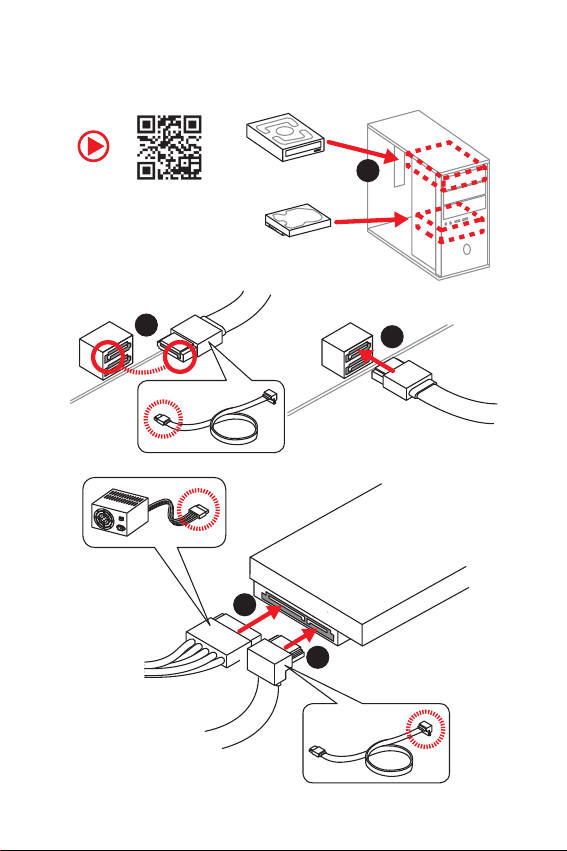
motherboard. This Quick Start section provides demonstration
diagrams about how to install your computer. Some of the
installations also provide video demonstrations. Please link to the
URL to watch it with the web browser on your phone or tablet. You
may have even link to the URL by scanning the QR code.
Kurzanleitung
Danke, dass Sie das MSI®B360I GAMING PRO AC Motherboard
gewählt haben. Dieser Abschnitt der Kurzanleitung bietet eine Demo
zur Installation Ihres Computers. Manche Installationen bieten
auch die Videodemonstrationen. Klicken Sie auf die URL, um diese
Videoanleitung mit Ihrem Browser auf Ihrem Handy oder Table
anzusehen. Oder scannen Sie auch den QR Code mit Ihrem Handy,
um die URL zu öffnen.
Présentation rapide
Merci davoir choisi la carte mère MSI®B360I GAMING PRO AC.
Ce manuel fournit une rapide présentation avec des illustrations
explicatives qui vous aideront à assembler votre ordinateur. Des
tutoriels vidéo sont disponibles pour certaines étapes. Cliquez sur
le lien fourni pour regarder la vidéo sur votre téléphone ou votre
tablette. Vous pouvez également accéder au lien en scannant le QR
code qui lui est associé.
ĭŧŝŞŜŧŕ ŝŞŌŜŞ
ĭŗŌŏŚŐŌŜŔŘ ŎŌŝ œŌ śŚŖşśŖş ŘŌŞőŜŔřŝŖŚŕ śŗŌŞŧ MSI®B360I
GAMING PRO AC. ĮũŞŚŘ ŜŌœŐőŗő śŜőŐŝŞŌŎŗőřŌ ŔřŠŚŜŘŌŢŔū,
ŖŚŞŚŜŌū śŚŘŚŒőŞ ŎŌŘ śŜŔ ŝōŚŜŖő ŖŚŘŨŪŞőŜŌ. İŗū řőŖŚŞŚŜŧš
ũŞŌśŚŎ ŝōŚŜŖŔ ŔŘőŪŞŝū ŎŔŐőŚŔřŝŞŜşŖŢŔŔ. İŗū śŜŚŝŘŚŞŜŌ
ŎŔŐőŚ, řőŚōšŚŐŔŘŚ ŚŞŖŜŧŞŨ ŝŚŚŞŎőŞŝŞŎşŪťşŪ ŝŝŧŗŖş Ŏ
Ŏőō-ōŜŌşœőŜő řŌ ŎŌŤőŘ ŞőŗőŠŚřő ŔŗŔ śŗŌřŤőŞő. Įŧ ŞŌŖŒő
ŘŚŒőŞő ŎŧśŚŗřŔŞŨ śőŜőšŚŐ śŚ ŝŝŧŗŖő, śşŞőŘ ŝŖŌřŔŜŚŎŌřŔū
QR-ŖŚŐŌ.

II Quick Start
1
2
3
6
45
7
8
9
Installing a Processor/ Installation des Prozessors/ Installer un
processeur/ ĿŝŞŌřŚŎŖŌ śŜŚŢőŝŝŚŜŌ
https://youtu.be/4ce91YC3Oww

III
Quick Start
Installing DDR4 memory/ Installation des DDR4-Speichers/
Installer une mémoire DDR4/ ĿŝŞŌřŚŎŖŌ śŌŘūŞŔ DDR4
http://youtu.be/T03aDrJPyQs
DIMMA1 DIMMB1
DIMMA1
1
2
2
3

IV Quick Start
RESET SW
POWER SW
POWER LED+
POWER LED-
HDD LED
HDD LED
RESET SW
JFP1
HDD LED HDD LED -
HDD LED +
POWER LED -
POWER LED +
POWER LED
Connecting the Front Panel Header/ Anschließen der
Frontpanel-Stiftleiste/ Connecter un connecteur du panneau
avant/ ĻŚŐŖŗŪţőřŔő ŜŌœŦőŘŚŎ śőŜőŐřőŕ śŌřőŗŔ
http://youtu.be/DPELIdVNZUI
1
210
9
JFP1
1 HDD LED + 2 Power LED +
3 HDD LED - 4 Power LED -
5 Reset Switch 6 Power Switch
7 Reset Switch 8 Power Switch
9 Reserved 10 No Pin

V
Quick Start
Installing the Motherboard/ Installation des Motherboards/
Installer la carte mère/ ĿŝŞŌřŚŎŖŌ ŘŌŞőŜŔřŝŖŚŕ śŗŌŞŧ
1
2

VI Quick Start
1
23
4
5
Installing SATA Drives/ Installation der SATA-Laufwerke/
Installer le disque dur SATA/ ĿŝŞŌřŚŎŖŌ ŐŔŝŖŚŎ SATA
http://youtu.be/RZsMpqxythc

VII
Quick Start
1
2
3
4
5
6
Installing a Graphics Card/ Einbau der Grafikkarte/ Installer
une carte graphique/ ĿŝŞŌřŚŎŖŌ ŐŔŝŖŜőŞřŚŕ ŎŔŐőŚŖŌŜŞŧ
http://youtu.be/mG0GZpr9w_A

VIII Quick Start
Connecting Peripheral Devices/ Peripheriegeräte/
Connecter un périphérique anschliessen/ ĻŚŐŖŗŪţőřŔő
śőŜŔŠőŜŔŕřŧš şŝŞŜŚŕŝŞŎ

IX
Quick Start
Connecting the Power Connectors/ Stromanschlüsse
anschliessen/ Connecter les câbles du module dalimentation/
ĻŚŐŖŗŪţőřŔő ŜŌœŦőŘŚŎ śŔŞŌřŔū
http://youtu.be/gkDYyR_83I4
ATX_PWR1 CPU_PWR1

XQuick Start
1
4
2
3
Power On/ Einschalten/ Mettre sous-tension/ ĮŖŗŪţőřŔő
śŔŞŌřŔū

1
Contents
Contents
Safety Information................................................................................................. 2
Specifications......................................................................................................... 3
Rear I/O Panel ....................................................................................................... 7
LAN Port LED Status Table..................................................................................... 7
Audio Ports Configuration...................................................................................... 7
Realtek HD Audio Manager .................................................................................... 8
Installing antennas............................................................................................... 10
Overview of Components .................................................................................... 11
CPU Socket ........................................................................................................... 12
DIMM Slots............................................................................................................ 13
PCI_E1: PCIe Expansion Slot................................................................................ 14
SATA1~4: SATA 6Gb/s Connectors ....................................................................... 14
M2_1~2: M.2 Slots (Key M) ................................................................................... 15
JFP1, JFP2: Front Panel Connectors................................................................... 16
JRGB1: RGB LED Connector ................................................................................ 16
CPU_PWR1, ATX_PWR1: Power Connectors ....................................................... 17
JAUD1: Front Audio Connector ............................................................................ 17
JUSB1: USB 2.0 Connector .................................................................................. 18
JUSB2: USB 3.1 Gen1 Connector ......................................................................... 18
CPU_FAN1, SYS_FAN1~2: Fan Connectors.......................................................... 19
JCI1: Chassis Intrusion Connector....................................................................... 20
JTPM1: TPM Module Connector........................................................................... 20
JBAT1: Clear CMOS (Reset BIOS) Jumper........................................................... 21
EZ Debug LED....................................................................................................... 21
BIOS Setup ........................................................................................................... 22
Entering BIOS Setup............................................................................................. 22
Resetting BIOS...................................................................................................... 23
Updating BIOS....................................................................................................... 23
EZ Mode ................................................................................................................ 24
Advanced Mode .................................................................................................... 26
OC Menu................................................................................................................ 27
Software Description........................................................................................... 32
Installing Windows®10......................................................................................... 32
Installing Drivers .................................................................................................. 32
Installing Utilities ................................................................................................. 32

2Safety Information
Safety Information
yThe components included in this package are prone to damage from electrostatic
discharge (ESD). Please adhere to the following instructions to ensure successful
computer assembly.
yEnsure that all components are securely connected. Loose connections may cause
the computer to not recognize a component or fail to start.
yHold the motherboard by the edges to avoid touching sensitive components.
yIt is recommended to wear an electrostatic discharge (ESD) wrist strap when
handling the motherboard to prevent electrostatic damage. If an ESD wrist strap is
not available, discharge yourself of static electricity by touching another metal object
before handling the motherboard.
yStore the motherboard in an electrostatic shielding container or on an anti-static pad
whenever the motherboard is not installed.
yBefore turning on the computer, ensure that there are no loose screws or metal
components on the motherboard or anywhere within the computer case.
yDo not boot the computer before installation is completed. This could cause
permanent damage to the components as well as injury to the user.
yIf you need help during any installation step, please consult a certified computer
technician.
yAlways turn off the power supply and unplug the power cord from the power outlet
before installing or removing any computer component.
yKeep this user guide for future reference.
yKeep this motherboard away from humidity.
yMake sure that your electrical outlet provides the same voltage as is indicated on the
PSU, before connecting the PSU to the electrical outlet.
yPlace the power cord such a way that people can not step on it. Do not place anything
over the power cord.
yAll cautions and warnings on the motherboard should be noted.
yIf any of the following situations arises, get the motherboard checked by service
personnel:
Liquid has penetrated into the computer.
The motherboard has been exposed to moisture.
The motherboard does not work well or you can not get it work according to user
guide.
The motherboard has been dropped and damaged.
The motherboard has obvious sign of breakage.
yDo not leave this motherboard in an environment above 60oC (140oF), it may damage
the motherboard.

3
Specifications
Specifications
CPU Supports 8th Gen Intel®Core™, Pentium®Gold and Celeron®
processors for Socket LGA1151
Chipset Intel®B360 Chipset
Memory
y2x DDR4 memory slots, support up to 32GB
ySupports DDR4 2666/ 2400/ 2133 MHz Memory
ySupports Dual-Channel mode
ySupports non-ECC, un-buffered memory
ySupports Intel®Extreme Memory Profile (XMP)
* Please refer www.msi.com for more information on compatible memory.
Expansion Slot y1x PCIe 3.0 x16 slot
Onboard Graphics
y1x DVI-D port, supports a maximum resolution of
1920x1200@60Hz
y1x DisplayPort port 1.2, supports a maximum resolution of
4096x2304@60Hz
Storage
Intel®B360 Chipset
y4x SATA 6Gb/s ports
y2x M.2 slots (Key M)
Support up to PCIe 3.0 x4 and SATA 6Gb/s*
Supports 2260 /2280 storage devices
Intel®Optane™ Memory Ready for M2_2 slot only**
* M2_2 slot supports PCIe M.2 SSD only.
** Before using Intel®Optane™ memory modules, please ensure that you have
updated the drivers and BIOS to the latest version from MSI website.
USB
Intel®B360 Chipset
y2x USB 3.1 Gen2 (SuperSpeed USB 10Gbps) Type-A ports
on the back panel
y4x USB 3.1 Gen1 (SuperSpeed USB) ports (2 Type-A ports
on the back panel, 2 ports available through the internal USB
connector)
y4x USB 2.0 (High-speed USB) ports (2 Type-A ports on
the back panel, 2 ports available through the internal USB
connector)
Audio yRealtek®ALC892 Codec
y7.1-Channel High Definition Audio
Continued on next page

4Specifications
Continued from previous page
LAN 1x Realtek®RTL8111H-C Gigabit LAN controller
Wirsless LAN &
Bluetooth®
Intel®Wireless-AC 9462 card
ySupports Wi-Fi 802.11 a/b/g/n/ac, Dual Band, MU-MIMO,
up to 433 Mbps speed.
ySupports Bluetooth®5
Back Panel
Connectors
y2 x Wi-Fi Antenna connectors
y1x DVI-D port
y1x DisplayPort port
y1x PS/2 keyboard/ mouse combo port
y2x USB 2.0 Type-A ports
y1x LAN (RJ45) port
y2x USB 3.1 Gen2 Type-A ports
y2x USB 3.1 Gen1 Type-A ports
y6x Audio jacks
Internal Connectors
y1x 24-pin ATX main power connector
y1x 8-pin ATX 12V power connector
y4x SATA 6Gb/s connectors
y1x USB 3.1 Gen1 connector (supports additional 2 USB 3.1
Gen1 ports)
y1x USB 2.0 connector (supports additional 2 USB 2.0 ports)
y1x 4-pin CPU fan connector
y2x 4-pin system fan connectors
y1x Front panel audio connector
y2x Front panel connectors
y1x 5050 RGB LED strip 12V connector
y1x TPM module connector
y1x Chassis Intrusion connector
y1x Clear CMOS jumper
I/O Controller NUVOTON NCT6797 Controller Chip
Continued on next page

5
Specifications
Continued from previous page
Hardware Monitor
yCPU/System temperature detection
yCPU/System fan speed detection
yCPU/System fan speed control
Form Factor ymini-ITX Form Factor
y6.7 in. x 6.7 in. (17.0 cm x 17.0 cm)
BIOS Features
y1x 128 Mb flash
yUEFI AMI BIOS
yACPI 6.1, SM BIOS 2.8
yMulti-language
Software
yDrivers
yAPP MANAGER
yCOMMAND CENTER
yLIVE UPDATE 6
ySMART TOOL
yRAMDISK
yDPC LATENCY TUNER
yFAST BOOT
yX-BOOST
yGAMING APP
ySUPER CHARGER
yMYSTIC LIGHT
yOpen Broadcaster Software (OBS)
yCPU-Z MSI GAMING
yIntel®Extreme Tuning Utility
yGoogle Chrome™ ,Google Toolbar, Google Drive
yNorton™ Internet Security Solution
Continued on next page

6Specifications
Continued from previous page
Special Features
yAudio
Audio Boost
yNetwork
Intel WiFi
yStorage
Twin Turbo M.2
yFan
Smart Fan Control
yLED
Mystic Light
Mystic Light Extension(RGB)
Mystic light SYNC
EZ DEBUG LED
yProtection
PCI-E Steel Armor
yPerformance
DDR4 Boost
yStability
7000+ Quality Test
yVR
VR Ready
yGamer Experience
GAMING HOTKEY
GAMING MOUSE Control
yBIOS
Click BIOS 5
yCertification
GAMING Certified

7
Rear I/O Panel
Rear I/O Panel
PS/2 LAN
Audio Ports
USB 3.1 Gen2
USB 3.1 Gen1
USB 2.0
DisplayPort
DVI-D
Link/ Activity LED
Status Description
Off No link
Yellow Linked
Blinking Data activity
Speed LED
Status Description
Off 10 Mbps connection
Green 100 Mbps connection
Orange 1 Gbps connection
LAN Port LED Status Table
Wi-Fi Antenna
connectors
Audio Ports Configuration
Audio Ports Channel
2468
Line-In
Line-Out/ Front Speaker Out ӪӪӪӪ
Mic In
Rear Speaker Out ӪӪӪ
Center/ Subwoofer Out ӪӪ
Side Speaker Out Ӫ
(Ӫ: connected, Blank: empty)

8Rear I/O Panel
Realtek HD Audio Manager
After installing the Realtek HD Audio driver, the Realtek HD Audio Manager icon will
appear in the system tray. Double click on the icon to launch.
yDevice Selection - allows you to select a audio output source to change the related
options. The check sign indicates the devices as default.
yApplication Enhancement - the array of options will provide you a complete guidance
of anticipated sound effect for both output and input device.
yMain Volume - controls the volume or balance the right/left side of the speakers that
you plugged in front or rear panel by adjust the bar.
yProfiles - toggles between profiles.
yAdvanced Settings - provides the mechanism to deal with 2 independent audio
streams.
yJack Status - depicts all render and capture devices currently connected with your
computer.
yConnector Settings - configures the connection settings.
Auto popup dialog
When you plug into a device at an audio jack, a dialogue window will pop up asking you
which device is current connected.
Each jack corresponds to its default setting as shown on the next page.
Jack Status
Device
Selection
Connector
Settings
Profiles
Main Volume
Application
Enhancement
Advanced
Settings

9
Rear I/O Panel
Audio jacks to headphone and microphone diagram
Audio jacks to stereo speakers diagram
Audio jacks to 7.1-channel speakers diagram
AUDIO INPUT
AUDIO INPUT
Rear Front
Side Center/
Subwoofer

10 Rear I/O Panel
Installing antennas
1. Screw the antennas tight to the antenna connectors as shown below.
2. Orient the antennas.
1
2
Table of contents
Languages:
Other MSI Motherboard manuals

MSI
MSI X370 GAMING M7 ACK User manual

MSI
MSI Baby AT SI19 User manual

MSI
MSI K7T266 Pro User manual

MSI
MSI PRESTIGE X570 CREATION User manual

MSI
MSI MS-7329 User manual

MSI
MSI MEG X570 GODLIKE User manual

MSI
MSI B250M PRO-VH User manual

MSI
MSI Z270 SLI PLUS User manual

MSI
MSI MS-9804 User manual

MSI
MSI MS-6390 User manual
Popular Motherboard manuals by other brands

Asus
Asus P6T6WS Revolution - Motherboard - ATX user manual

Asus
Asus M2R32-MVP - Motherboard - ATX user manual

REPUBLIC OF GAMERS
REPUBLIC OF GAMERS ROG STRIX B550-F GAMING quick start guide

Apollo
Apollo P55KTX user manual

Gigabyte
Gigabyte GA-7VX user manual

Gigabyte
Gigabyte Z790 AORUS Elite AX user manual