MSI MD-3000 User manual

i
Version 1.0
MD-3000 Micro ATX Mainboard
MSI
MICRO-STAR INTERNATIONAL

ii
Manual Rev: 1.0
Release Date: Dec. 2001
FCC-B Radio Frequency Interference Statement
This equipment has been tested and found to comply with the limits for a class
B digital device, pursuant to part 15 of the FCC rules. These limits are designed
to provide reasonable protection against harmful interference when the equip-
ment is operated in a commercial environment. This equipment generates, uses
and can radiate radio frequency energy and, if not installed and used in accor-
dance with the instruction manual, may cause harmful interference to radio
communications. Operation of this equipment in a residential area is likely to
cause harmful interference, in which case the user will be required to correct
the interference at his own expense.
Notice 1
The changes or modifications not expressly approved by the party respon-
sible for compliance could void the user’s authority to operate the equipment.
Notice 2
Shielded interface cables and A.C. power cord, if any, must be used in order to
comply with the emission limits.
VOIR LA NOTICE D’INSTALLATION AVANT DE RACCORDER AU
RESEAU.
Micro-Star International MD-3000
Tested to comply
with FCC Standard
For Home or Office Use

iii
Edition
Dec. 2001
Copyright Notice
The material in this document is the intellectual property of MICRO-STAR
INTERNATIONAL. We take every care in the preparation of this document,
but no guarantee is given as to the correctness of its contents. Our products
are under continual improvement and we reserve the right to make changes
without notice.
Trademarks
All trademarks are the properties of their respective owners.
AMD, Athlon and Duron are registered trademarks of AMD Corporation.
PS/2 and OS®/2 are registered trademarks of International Business Machines
Corporation.
Windows®95/98/2000/NT/ME/XP are registered trademarks of Microsoft
Corporation.
Netware®is a registered trademark of Novell, Inc.
Award®is a registered trademark of Phoenix Technologies Ltd.
AMI®is a registered trademark of American Megatrends Inc.
Revision History
Revision Revision History Date

iv
1. Always read the safety instructions carefully.
2. Keep this User’s Manual for future reference.
3. Keep this equipment away from humidity.
4. Lay this equipment on a reliable flat surface before setting it up.
5. The openings on the enclosure are for air convection hence protects the
equipment from overheating. DO NOT COVER THE OPENINGS.
6. Make sure the voltage of the power source and adjust properly 110/220V
before connecting the equipment to the power inlet.
7. Place the power cord such a way that people can not step on it. Do not
place anything over the power cord.
8. Always Unplug the Power Cord before inserting any add-on card or module.
9. All cautions and warnings on the equipment should be noted.
10. Never pour any liquid into the opening that could damage or cause electri-
cal shock.
11. If any of the following situations arises, get the equipment checked by a
service personnel:
!The power cord or plug is damaged
!Liquid has penetrated into the equipment
!The equipment has been exposed to moisture
!The equipment has not work well or you can not get it work according
to User’s Manual.
!The equipment has dropped and damaged
!If the equipment has obvious sign of breakage
12. DO NOT LEAVE THIS EQUIPMENT IN AN ENVIRONMENT
UNCONDITIONED,STORAGETEMPERATUREABOVE600
C(1400F),IT
MAY DAMAGE THE EQUIPMENT.
Safety Instructions
CAUTION: Danger of explosion if battery is incorrectly replaced.
Replace only with the same or equivalent type recommended by the
manufacturer.

v
CONTENTS
Chapter 1. Getting Started ........................................................................ 1-1
Mainboard Specification ...................................................................... 1-2
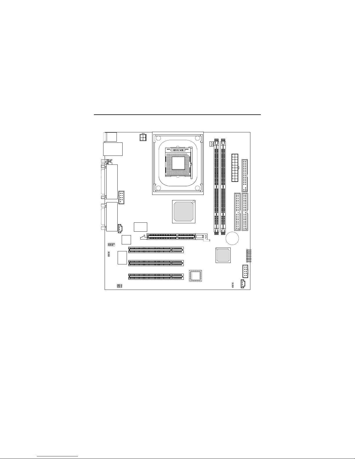
Mainboard Layout ............................................................................... 1-4
Chapter 2. Hardware Setup ....................................................................... 2-1
Central Processing Unit: CPU .............................................................. 2-2
CPU Installation Procedures ......................................................... 2-2
CPU Core Speed Derivation Procedure ......................................... 2-3
Memory ................................................................................................ 2-4
Introduction to SDRAM ............................................................... 2-4
DIMM Module Combination ......................................................... 2-5
Installing DIMM Modules ............................................................ 2-5
Power Supply ....................................................................................... 2-6
ATX 20-Pin Power Connector ....................................................... 2-6
ATX 12V Power Connector: JPW1 ................................................ 2-6
Back Panel ............................................................................................ 2-7
Mouse Connector: JKBMS1 ......................................................... 2-7
Keyboard Connector: JKBMS1 ..................................................... 2-8
USB Connectors ............................................................................ 2-8
LAN (RJ-45) Jack ........................................................................... 2-9
Serial Port Connector: COM A & COM B1 .................................... 2-9
Joystick/Midi Connectors ........................................................... 2-10
Audio Port Connectors ............................................................... 2-10
SPDIF Connectors ....................................................................... 2-10
Parallel Port Connector: LPT1 ...................................................... 2-11
Connectors ......................................................................................... 2-12
Floppy Disk Drive Connector: FDD1 ........................................... 2-12
Hard Disk Connectors: IDE1 & IDE2 ........................................... 2-13
CD-In Connector: CD_IN1 .......................................................... 2-14
Front Audio Line-out Connector: JAUDIO1 ............................... 2-14

vi
Fan Power Connectors: C_FAN1 ................................................. 2-15
Front Panel Connector: FP_1 ....................................................... 2-16
Front USB Connector: USB1 ....................................................... 2-17
SPDIF Bracket Jumper: JSPDIF1 .................................................. 2-18
Jumpers .............................................................................................. 2-19
Clear CMOS Jumper: JBAT1 ........................................................ 2-19
LAN Enable/Disable Jumper: JLAN1 ........................................... 2-20
Center/Bass Setting Jumper: J11 & J12 ........................................ 2-21
Slots ................................................................................................... 2-22
AGP (Accelerated Graphics Port) Slot ......................................... 2-22
PCI Slots ...................................................................................... 2-22
PCI Interrupt Request Routing .................................................... 2-23
Appendix A: Using SPDIF & 4-/6-channel Audio Function ..................... A-1

Getting Started
1-1
Chapter 1. Getting Started 1
Getting Started
Congratulations on purchasing the MSI mainboard. MD-3000 Micro
ATX mainboard is an excellent computer mainboard based on the innova-
tive Intel®Brookdale and ICH2 chipset, which supports the Intel®
Pentium 4 processor and provides you with a cost-effective solution.
TOPICS
Mainboard Specification 1-2
Mainboard Layout 1-5
MSI Special Features 1-6

Chapter 1
1-2
Mainboard Specification
CPU
Support Socket478 for Intel®Pentium 4(FC-PGA2) processor
Support 1.3GHz, 1.4GHz and up to 2.XGHz
Chipset
Intel®Brookdale chipset
- AGP 4x/2x universal slot
- Support 100MHz FSB
- Support 400MHz Intel NetBurst micro-architecture bus.
Intel®ICH2 chipset (360 BGA)
- AC’97 Controller integrated
- 2 full IDE channels, up to ATA100
- Integrated 10/100Mbit/sec Etherent
- Low pin count interface for Winbond SIO
MainMemory (This section refers only to S-DRAM Layout)
Support two 168-pin DIMM sockets
Support a 32 to 1GB memory using 512Mbit technology
Max. memory size: 2GB
Slots
One AGP (Accelerated Graphics Port) 2x/4x slot
Two PCI 2.2 32-bit Master PCI Bus slots, the third PCI can support 2
Master devices
Support 3.3v/5v PCI bus interface
On-boardIDE
An IDE controller on the ICH2 chipset provides IDE HDD/CD-ROM
with PIO, Bus Master and Ultra DMA 66/ 100 operation modes
Can connect to four IDE devices

Getting Started
1-3
On-board Peripherals
One floppy port that supports two FDD with 360KB, 720KB, 1.44MB
and 2.88MB
Two serial ports (COM A/ Reserved in pin header)
One parallel port that supports SPP/EPP/ECP modes
Four USB ports (2 rear connectors and 2 USB front pin header)
One RJ-45 connector
One Line-In/ 3 Line-Out/Game port
Network
Realtek 8100 single chip fast 10/100 Mb/s Ethernet controller
ACPI, APM supported
H/W Audio (option)
C-media CMI8738-6CH-MX
Support 6 channel audio
AC’97 2.1 compliant
Support SPDIF
BIOS
The mainboard BIOS provides “Plug & Play” BIOS that can detect
the periph-eral devices and expansion cards installed on the board
automatically
Support Desktop Management Interface (DMI) function that can record
your mainboard specifications
Dimension
Micro ATX Form Factor (24.4cm x 22.4cm)
Mounting
6 mounting holes

Chapter 1
1-4
Mainboard Layout
MD-3000 Micro ATX Mainboard
AGP Slot
JAUDIO1
USB1
FP_1
ATX
Power Supply
JLAN1
JSPDIF1
J12
J11 JBAT1
IDE 1
Winbond
W83627HF-AW
RTL
8100L
C-media
CMI8738
IDE 2
DIMM 1
DIMM 2
Top : Parallel Port
Bottom:
COM A
SPDIF IN/OUT
Top : mou se
Bottom: keyboard
Top: LAN Jack
Bottom: USB
ports
To p :
Game port
Bottom:
Line-Out
Line-In
Mic
COM B1
CD_IN1
JPW1
C_FAN1
PCI Slot 1
PCI Slot 2
PCI Slot 3
BATT
+
ICH2
Intel
Brookdale
Chipset
FWH
FDD1

Hardware Setup
2-1
Chapter 2. Hardware Setup
This chapter provides you with the information about hardware setup
procedures. While doing the installation, be careful in holding the compo-
nents and follow the installation procedures. For some components, if you
install in the wrong orientation, the components will not work properly.
Use a grounded wrist strap before handling computer components. Static
electricity may damage the components.
TOPICS
Central Processing Unit: CPU 2-2
Memory 2-5
Power Supply 2-7
Back Panel 2-8
Connectors 2-13
Jumpers 2-20
Slots 2-23
2
Hardware Setup

Chapter 2
2-2
Open Lever
Dot / Cut edge
Sliding
Plate
Close
Lever
Central Processing Unit: CPU
The mainboard supports Intel®Pentium®4 processor in the 478 pin
package. The mainboard uses a CPU socket called PGA478 for easy CPU
installation. When you are installing the CPU, make sure the CPU has a heat
sinkandacoolingfanattachedonthetoptopreventoverheating. Ifyoudonot
find the heat sink and cooling fan, contact your dealer to purchase and install
them before turning on the computer.
1. Pull the lever sideways away
from the socket. Then, raise
the lever up to a 90-degree
angle.
2. Lookfor the dot/cut edge. The
dot/cut edge should point to-
wards the lever pivot. The
CPU will only fit in the correct
orientation.
3. HoldtheCPUdownfirmly,and
then close the lever to com-
plete the installation.
CPUInstallationProcedures
Overheating will seriously damage the CPU and system,
always make sure the cooling fan can work properly to
protect the CPU from overheating.
WARNING!

Hardware Setup
2-3
CPU Core Speed Derivation Procedure
If CPUClock = 100MHz
Core/Bus ratio = 14
then CPU core speed = Host Clock x Core/Bus ratio
= 100MHzx14
= 1.4GHz
Overclocking
This motherboard is designed to support overclocking.
However, please make sure your components are able to
tolerate such abnormal setting, while doing overclocking.
Any attempt to operate beyond product specifications is
not recommended. We do not guarantee the damages or
risks caused by inadequate operation or beyond product
specifications.
WARNING!

Chapter 2
2-4
The mainboard provides 2 slots for 168-pin, 3.3V SDRAM DIMM with 4
memory banks. You can install PC133/PC100 SDRAM modules on the DIMM
slots (DIMM 1~2). Advice: DDR Modules have only one notch!
Memory (This section describes only S-DRAM
DIMM Slots
(DIMM 1~2)
Introduction to SDRAM
Synchronous DRAM (SDRAM) is a type of dynamic RAM memory
chip that has been widely used starting in the latter part of the 1990s. SDRAMs
are based on standard dynamic RAM chips, but have sophisticated features
that make them considerably faster. First, SDRAM chips are fast enough to be
synchronized with the CPU's clock, which eliminates wait states. Second, the
SDRAM chip is divided into two cell blocks, and data is interleaved between
the two so that while a bit in one block is being accessed, the bit in the other is
being prepared for access. This allows SDRAM to burst the second and
subsequent, contiguous characters at a rate of 10ns, compared to 60ns for the
first character.
SDRAM provides 800 MBps or 1 GBps data transfer depending on
whether the bus is 100MHz or 133MHz.

Hardware Setup
2-5
To operate properly,atleastone DIMM module must beinstalled. Memory
modules can be installed on the slots in any order. You can install either single-
or double-sided modules to meet your own needs.
Memory modules can be installed in any combination as follows:
Slot Memory Module Total Memory
DIMM 1
(Bank 0 & Bank 1) S/D 32MB~1GB
DIMM 2
(Bank 2 & Bank 3) S/D 32MB~1GB
Maximum System Memory Supported 32MB~2GB
DIMM Module Combination
S: Single Side D: Double Side
1. Insert the DIMM memory module vertically into the DIMM slot. Then push
it in.
2. The plastic clip at each side of the DIMM slot will automatically close.
Installing DIMM Modules
The DIMM slot has 2 Notch Keys “VOLT and DRAM”. The module will
only fit in the right orientation.
VOLT notch
DRAM notch

Chapter 2
2-6
Power Supply
ATX20-PinPowerConnector
This connector allows you to connect to an ATX power supply. To
connect to the ATX power supply, make sure the plug of the power supply is
inserted in the proper orientation and the pins are aligned. Then push down
the power supply firmly into the connector.
The mainboard supports ATX power supply for the power system. Be-
fore inserting the power supply connector, always make sure that all compo-
nents are installed properly to ensure that no damage will be caused.
ATX 12VPowerConnector:JPW1
This 12V power connector is used to provide power to the CPU.
PIN SIGNAL
1 GND
2 GND
3 12V
4 12V
JPW1 Pin Definition PIN SIGNAL
11 3.3V
12 -12V
13 GND
14 PS_ON
15 GND
16 GND
17 GND
18 -5V
19 5V
20 5V
PIN SIGNAL
1 3.3V
2 3.3V
3 GND
45V
5 GND
65V
7 GND
8 PW_OK
9 5V_SB
10 12V
ATX Power Supply Pin Definition
10
1
20
11
JPW1
1
3
2
4

Hardware Setup
2-7
The Back Panel provides the following connectors:
Back Panel
Mouse Connector: JKBMS1
The mainboard provides a standard PS/2®mouse mini DIN connector for
attaching a PS/2®mouse. You can plug a PS/2®mouse directly into this
connector. The connector location and pin assignments are as follows:
Mouse
Keyboard USB
Parallel
COM A SPDIF
IN Line-in
Midi/Joystick
PIN SIGNAL DESCRIPTION
1 MouseDATA MouseDATA
2 NC Noconnection
3 GND Ground
4 VCC +5V
5 Mouse Clock Mouse clock
6 NC Noconnection
Pin Definition
PS/2 Mouse (6-pin Female)
21
3
4
5
6
LAN
SPDIF
OUT
Line-out (Front)
(2 Channel output speaker)
Line-out (Rear)
(2 Channel output speaker)
Center / Bass
(2 Channel output speaker)

Chapter 2
2-8
Keyboard Connector: JKBMS1
The mainboard provides a standard PS/2®keyboard mini DIN connector
for attaching a PS/2®keyboard. You can plug a PS/2®keyboard directly into
this connector.
USB Connectors
The mainboard provides a UHCI (Universal Host Controller Interface)
Universal Serial Bus root for attaching USB devices such as keyboard, mouse
or other USB-compatible devices. You can plug the USB device directly into
the connector.
PIN SIGNAL DESCRIPTION
1 VCC +5V
2 -Data0 NegativeDataChannel0
3 +Data0 PositiveData Channel 0
4 GND Ground
5 VCC +5V
6 -Data1 NegativeDataChannel1
7 +Data1 PositiveData Channel 1
8 GND Ground
PIN SIGNAL DESCRIPTION
1 Keyboard DATA Keyboard DATA
2 NC Noconnection
3 GND Ground
4 VCC +5V
5 KeyboardClock Keyboardclock
6 NC Noconnection
Pin Definition
USB Port Description
USB Ports
1 2 3 4
5 6 7 8
PS/2 Keyboard (6-pin Female)
21
3
4
5
6

Hardware Setup
2-9
Serial Port Connector: COM A & COM B1
The mainboard offers two 9-pin male DIN connectors for serial port COM
A and COM B1. The ports are 16550A high speed communication ports that
send/receive 16 bytes FIFOs. You can attach a serial mouse or other serial
devices directly to them.
PIN SIGNAL DESCRIPTION
1 DCD Data Carry Detect
2 SIN Serial In or Receive Data
3 SOUT Serial Out or Transmit Data
4 DTR Data Terminal Ready)
5 GND Ground
6 DSR DataSet Ready
7 RTS RequestToSend
8 CTS Clear ToSend
9 RI RingIndicate
Pin Definition
9-Pin Male DIN Connectors
1 2 3 4
6 7 8 9
COM A
1 2 3 4 5
6 7 8 9
COM B1
LAN (RJ-45) Jack
The mainboard provides one standard RJ-45 jack for connection to Local
Area Network (LAN). You can connect a network cable to the LAN jack.
Pin Definition
PIN SIGNAL DESCRIPTION
1 TDP Transmit Differential Pair
2 TDN Transmit Differential Pair
3 RDP Receive Differential Pair
4 NC NotUsed
5 NC NotUsed
6 RDN Receive Differential Pair
7 NC NotUsed
8 NC NotUsed

Chapter 2
2-10
Joystick/Midi Connectors
You can connect a joystick or game pad to this connector.
SPDIFConnectors
The SPDIF connectors privided on the back pannel can be used to con-
nect your digital audio equipment.
SPDIF
IN SPDIF
OUT
AudioPortConnectors
Line In is used for external CD
player, Tape player, or other audio
devices. Line Out are connectors for
Speakers or Headphones. Center/Bass
is a connector for audio device which is
used as a center speaker or supports
bass effect.
Note: Details on the appli-
cation of 6-channel audio can be
acquired in Appendix A.
Line-in
Line-out (Front)
(2 Channel output speaker)
Line-out (Rear)
(2 Channel output speaker)
Center / Bass
(2 Channel output speaker)
Note: Details on the application of 6-channel audio can be acquired
in Appendix A.
Table of contents
Other MSI Motherboard manuals

MSI
MSI MS-7242 Instructions for use

MSI
MSI MS-6176 User manual

MSI
MSI X79A-GD45 (8D) series User manual

MSI
MSI Z790-S01 User manual

MSI
MSI MEG Z690I UNIFY User manual

MSI
MSI B760 GAMING PLUS WIFI User manual

MSI
MSI MS-6380 LE2 User manual

MSI
MSI H6M-P30 (B3) User manual

MSI
MSI MS-7320 User manual

MSI
MSI Z87-G41 PC Mate User manual

MSI
MSI H67MA-E35 B3 series User manual

MSI
MSI 945GM2-FR User manual

MSI
MSI 7978-003R User manual

MSI
MSI 990FXA User manual

MSI
MSI K9NBPM2-FID Series User manual

MSI
MSI H97M-G43 User manual

MSI
MSI C847MS-E33 Series User manual

MSI
MSI A88X-G45 GAMING User manual

MSI
MSI PRO B660M-A WIFI DDR4 User manual

MSI
MSI Creator X299 User manual